Project 2_Design & Analysis of a Hostel building at Guwahati, Assam
INTRODUCTIONS:-
- Etabs is the software which is being used to create a structural model of given building.
- In the first step note down the values of grid spacing from the given structural plans.
- Next Create the Structural model and run the Model
- Analyse the result and note down the result values from ETABS.
- Next is to export the model to SAFE 2016 software in order to design the foundations
PROCEDURE:-
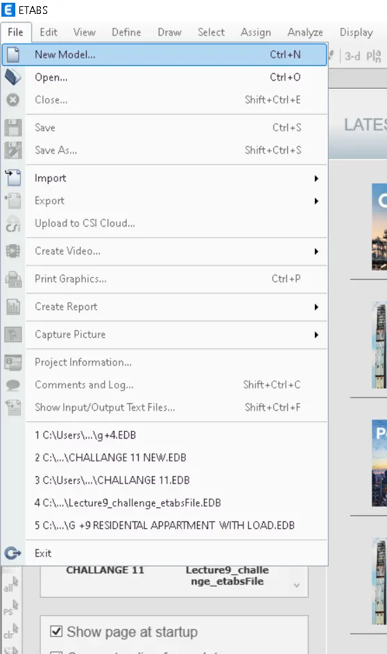
- In the first step open the etabs software go to file and click on new model.
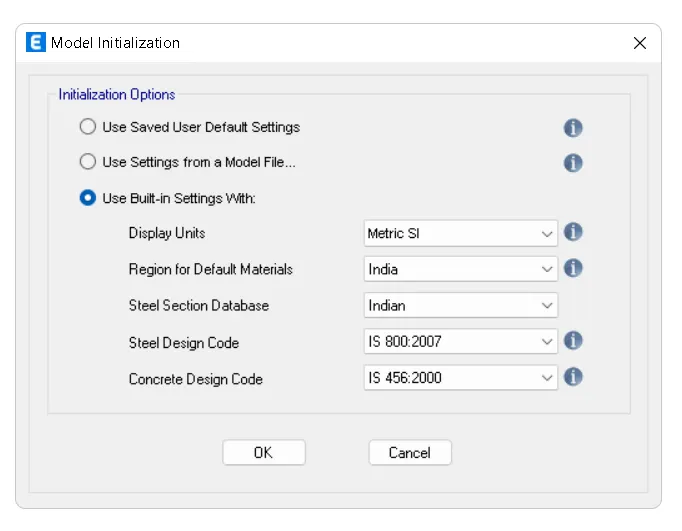
- Click on the use built in setting and select the indian codes and click ok.
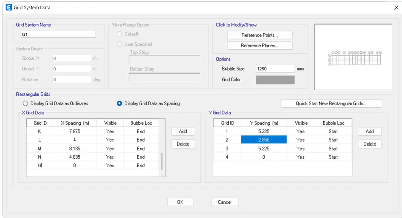
- Click on the custom grid data and click ok.
- Now the values as per the given plans are inserted and our model will be ready.
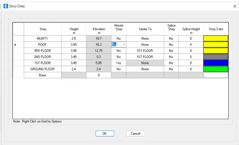
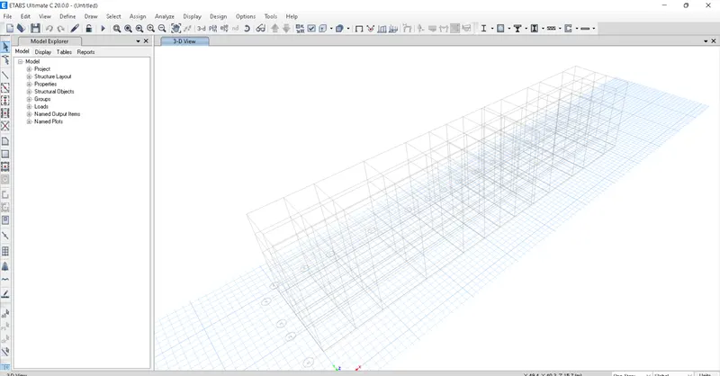
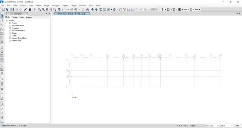
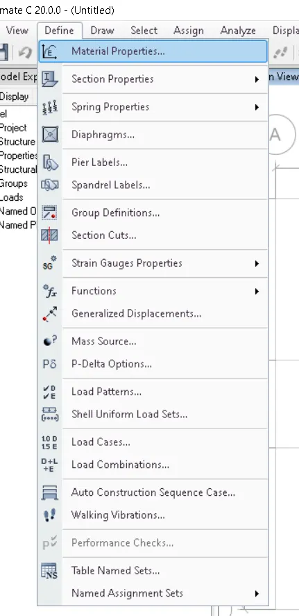
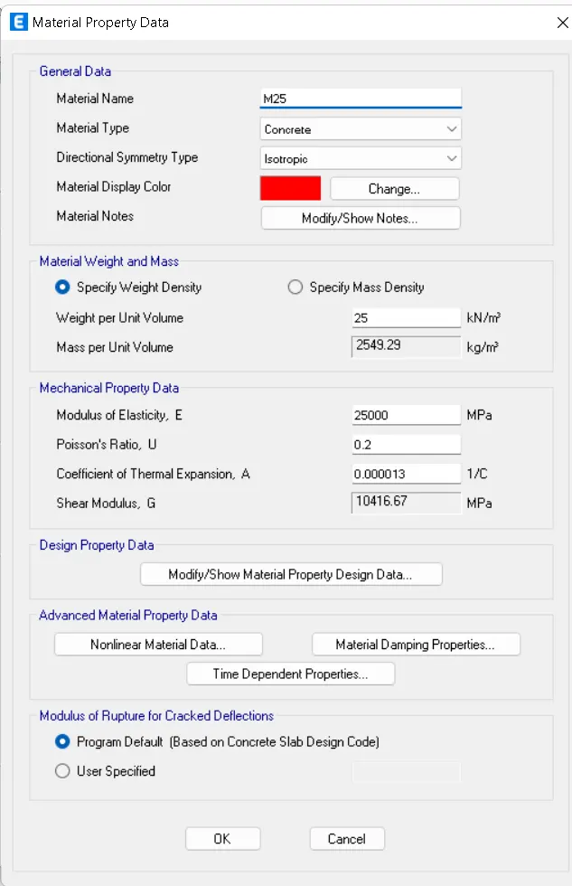
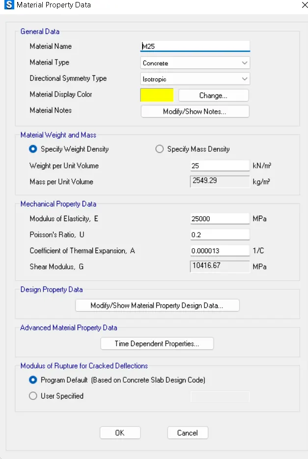
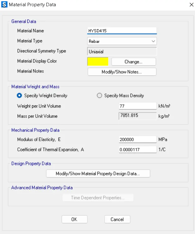
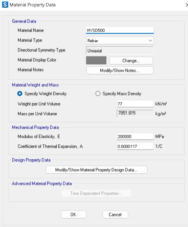
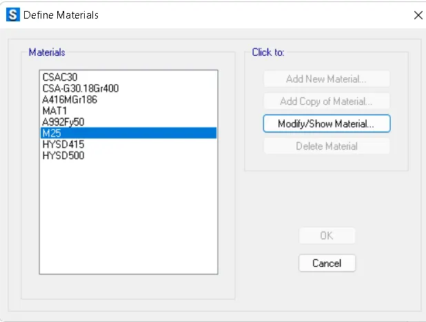
- In the next step material has to be defined. Go to define and click on material properties and add the concrete and rebar material specification.
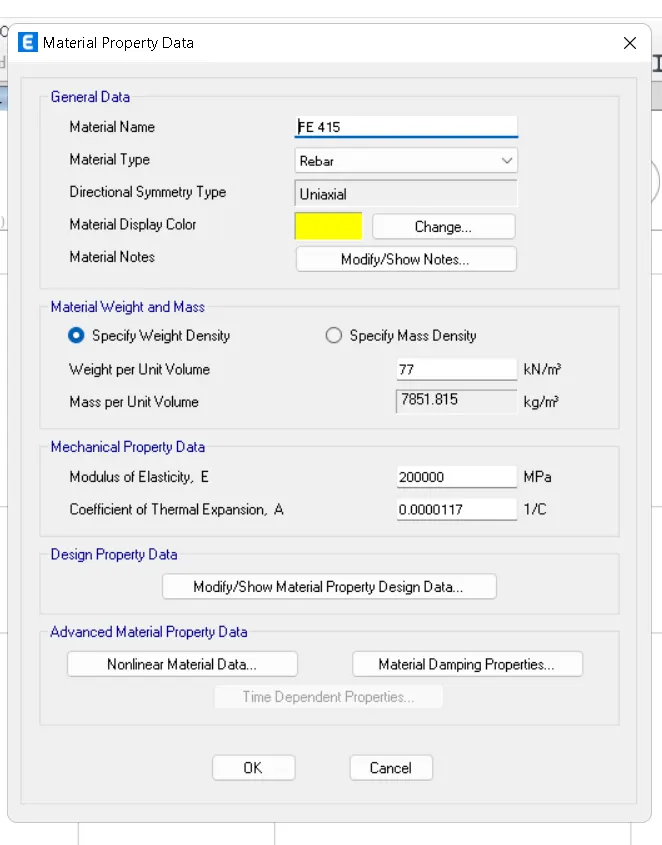
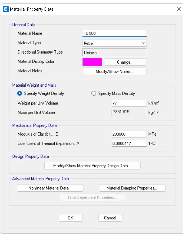
- Go to the section properties. Go to frame Section and click ok
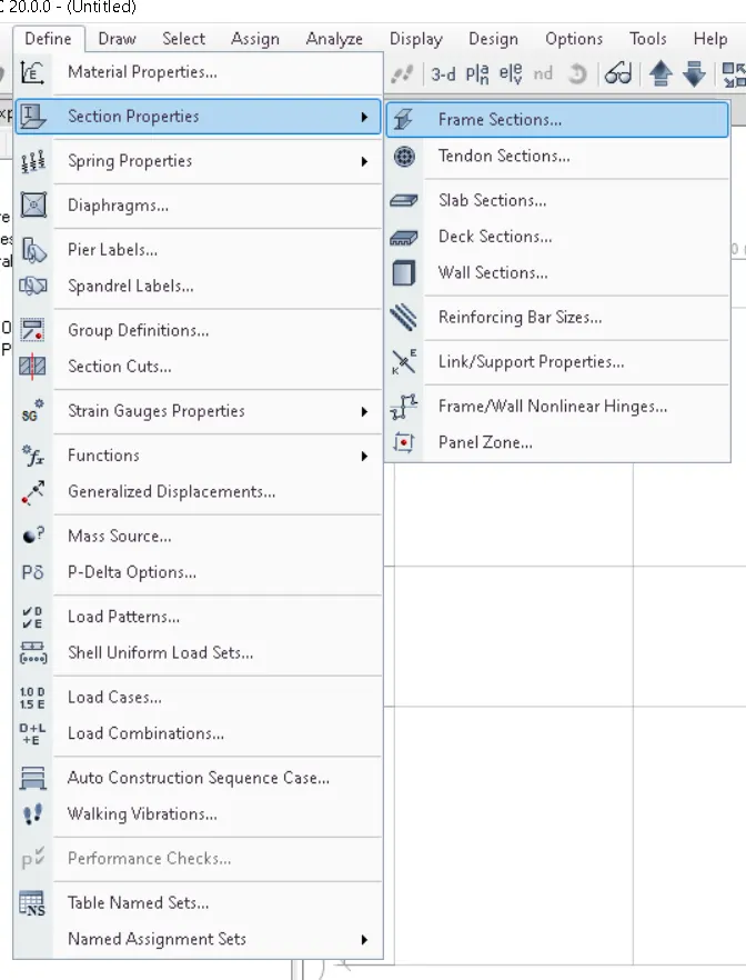
- Click on the Add New Properties.
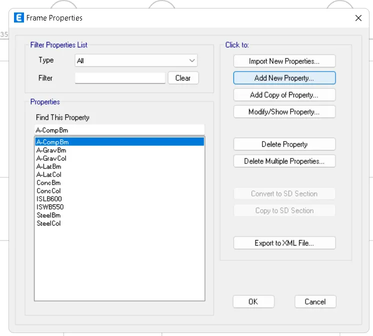
- Click on the Concrete .
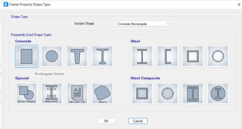
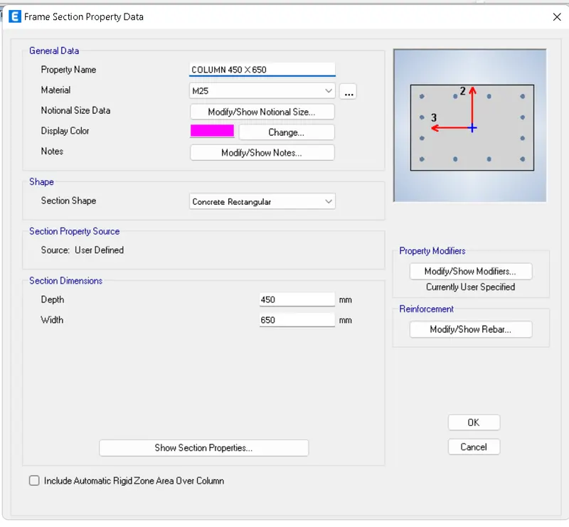
- Now Add 450 mm x 550 mm column size is provided for the all the columns.
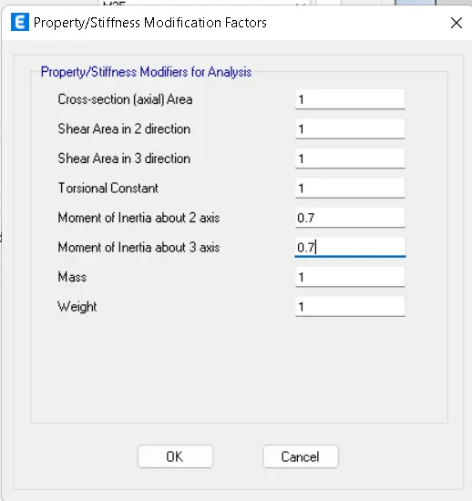
- Now go to properties/stiffness Modification and give moment of inertia 0.7 in both 2 and 3 axix.
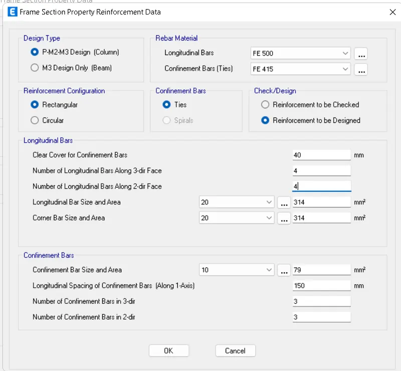
- Now go to the frame section properties and select column and click ok.
- Now again go to add new properties
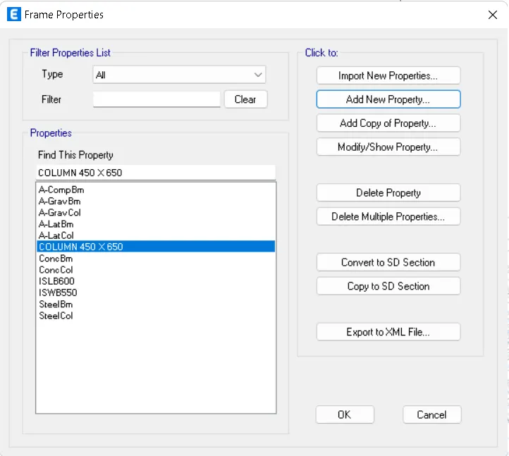
- Now again select concrete and click ok.
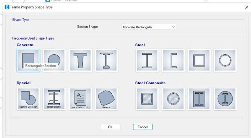
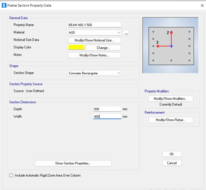
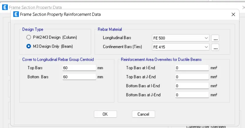
- Now add 450 mm x 550 mm beams
- Now change the properties name ,material,depth and width
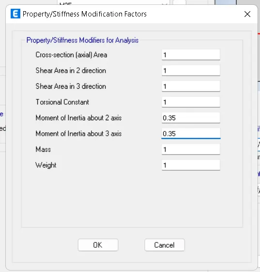
- Now go to properties / stiffness Modification and give moment of inertia 0.35 in both 2 and 3 axix.
- Now go to frame section properties and select beam and click ok.
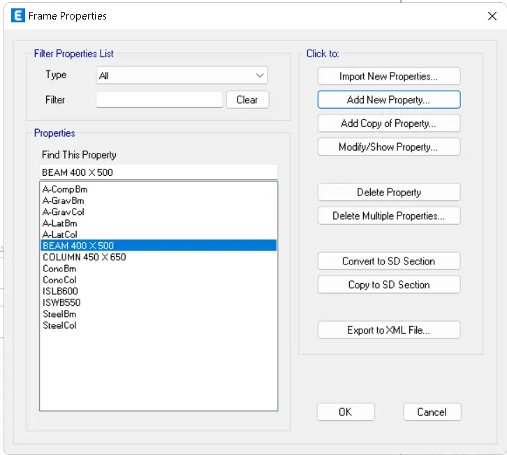
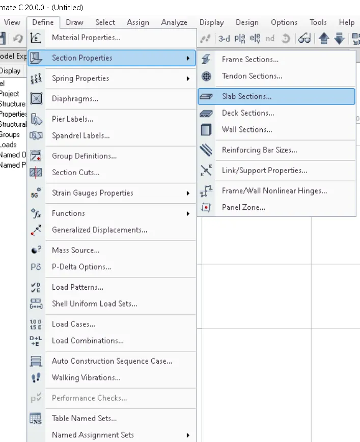
- In the next step define the slab properties by going in to define and slab sections.
- click to add New Properties.
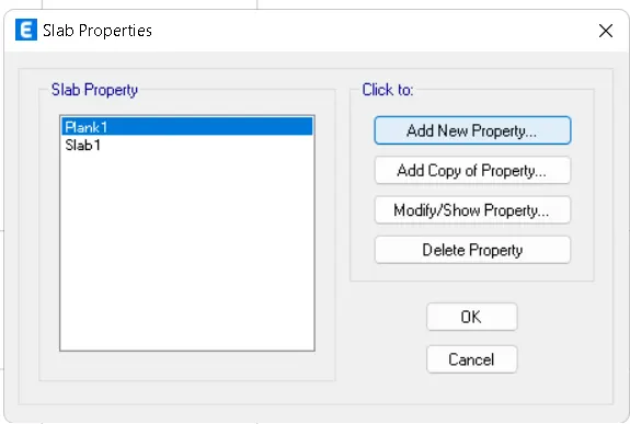
- Add Slab -125mm thickness ,slab material -M25 nad Modelling type- Membrance
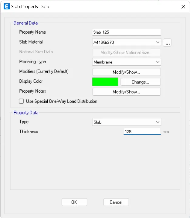
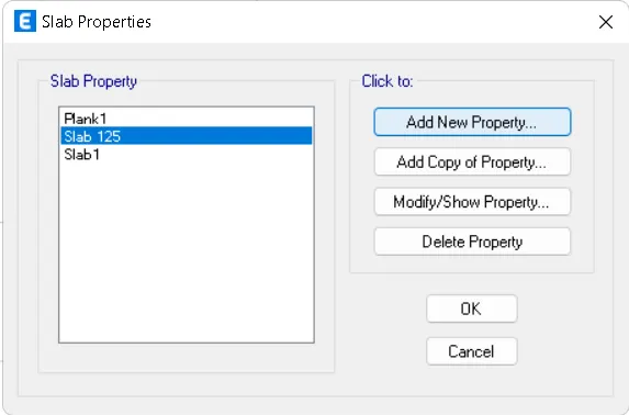
- Now Again Add New properties for stair case slab
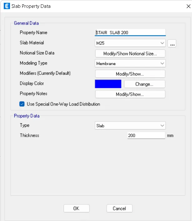
- stair case slab and provide thickness as 200 and Click on One Way Load Distribution.
- then click ok
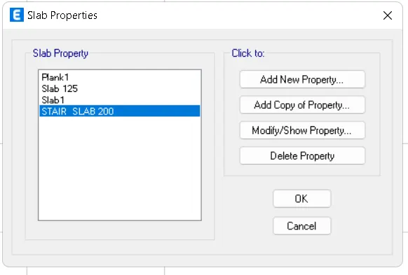
- Now we have to draws all the columns and beams
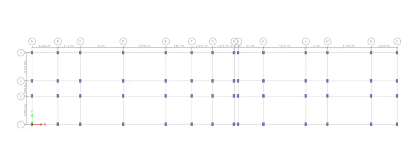
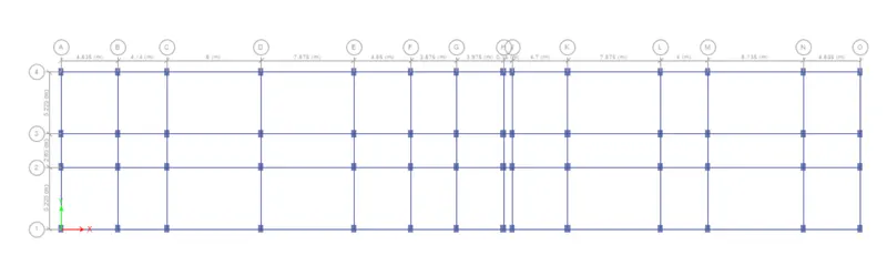
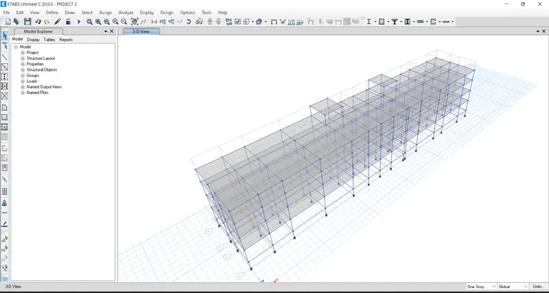
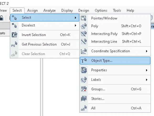
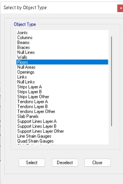
- Now slabs are drawn using Quick drw Floor option and select slab125 and select Stair slab for stair case area.
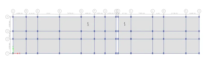
- Now select the Stair Caseare of One way Load.
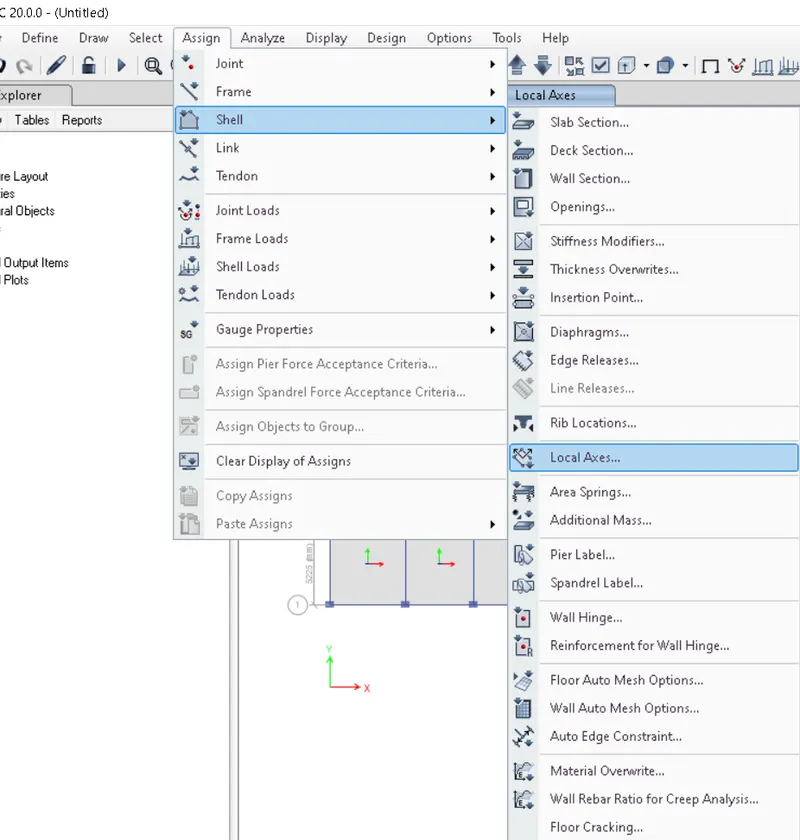
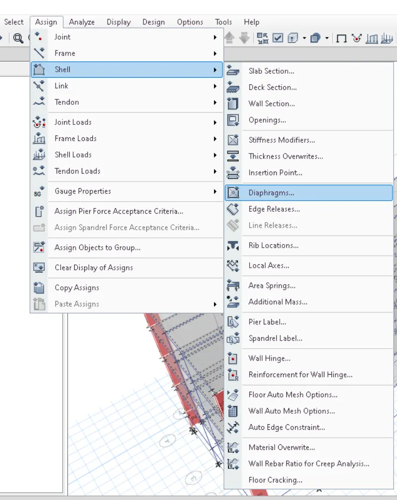
- Go to the assign <shell
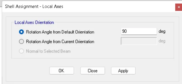
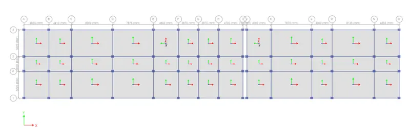
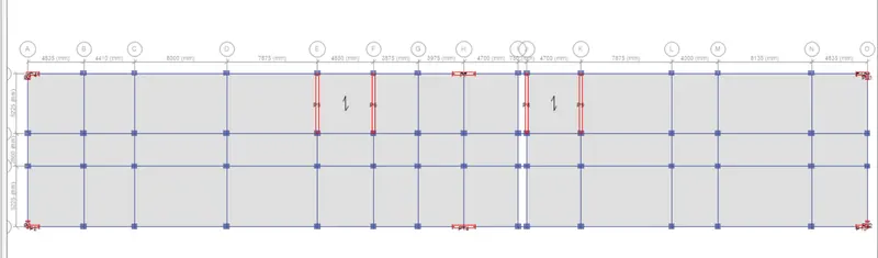
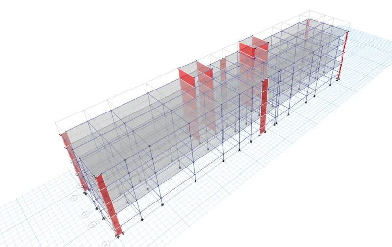
- Now we have to decide the location of shear walls and how much should be the length of the shear wall.
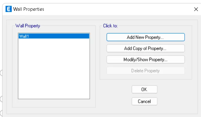
- Go to the define
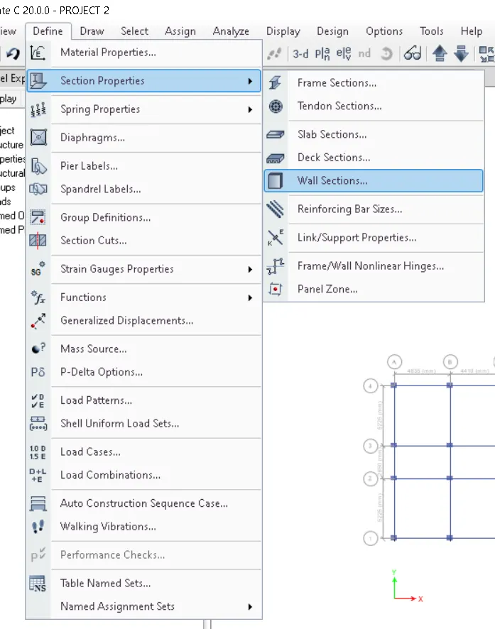
- Now Add new properties
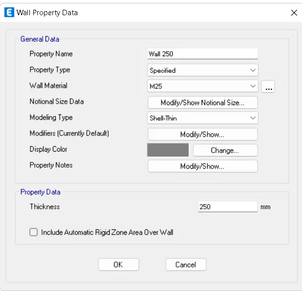
- Add 250mm Wall thickness
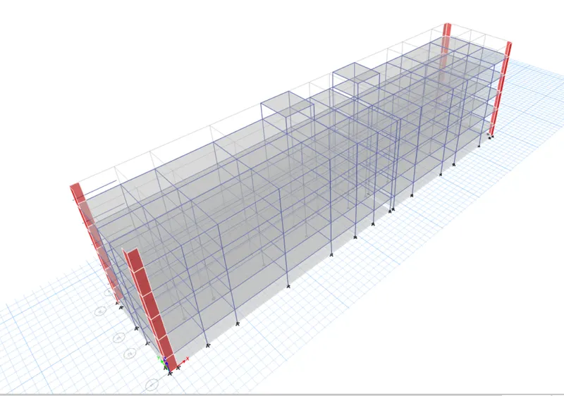
- 3d view
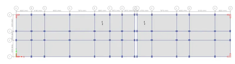
- Now go to define
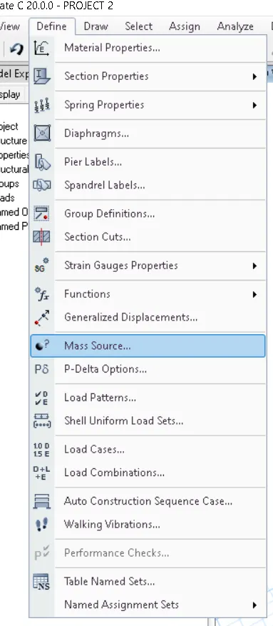
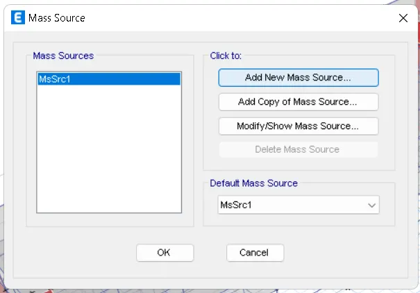
- Add New Mass Source.
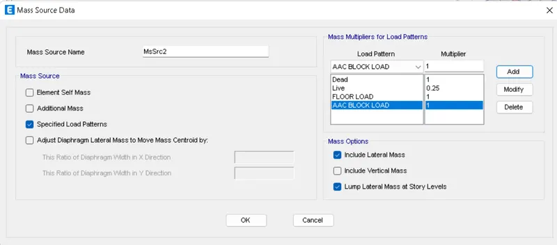
- Add multiple Load Pattern
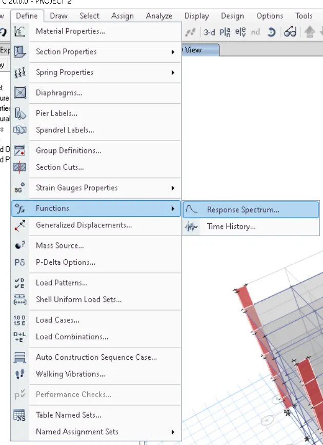
- Now Go to Define < function < response spectrum.
- Add new Function
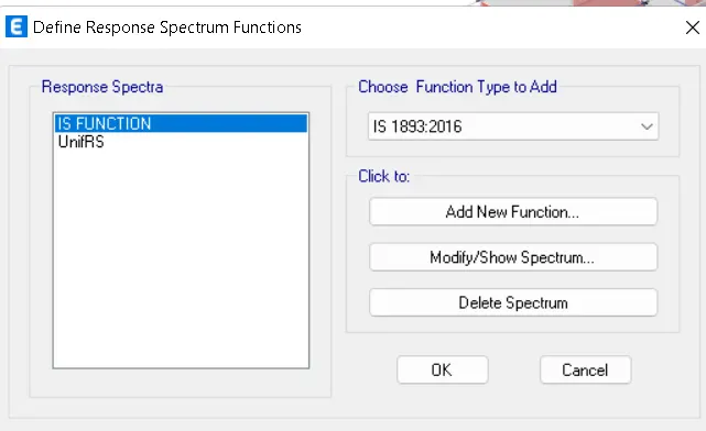
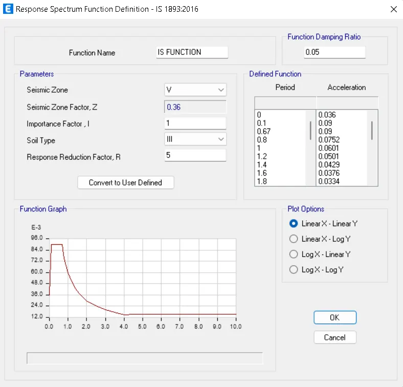
- Now go to define and define the loads.
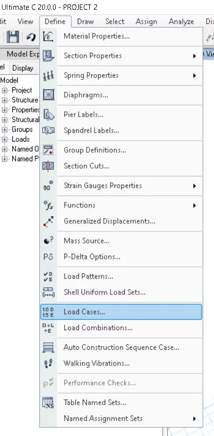
- add new Load case
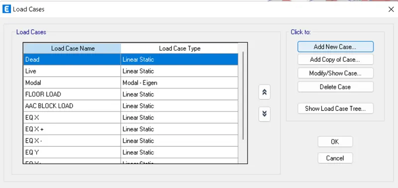
- now go to define Load cases and click on Add new case and Add RSX and Rsy
- select the response spectrum click on Add select the function as IS function and U1 for Rx, and U 2 for Rsy and IS function
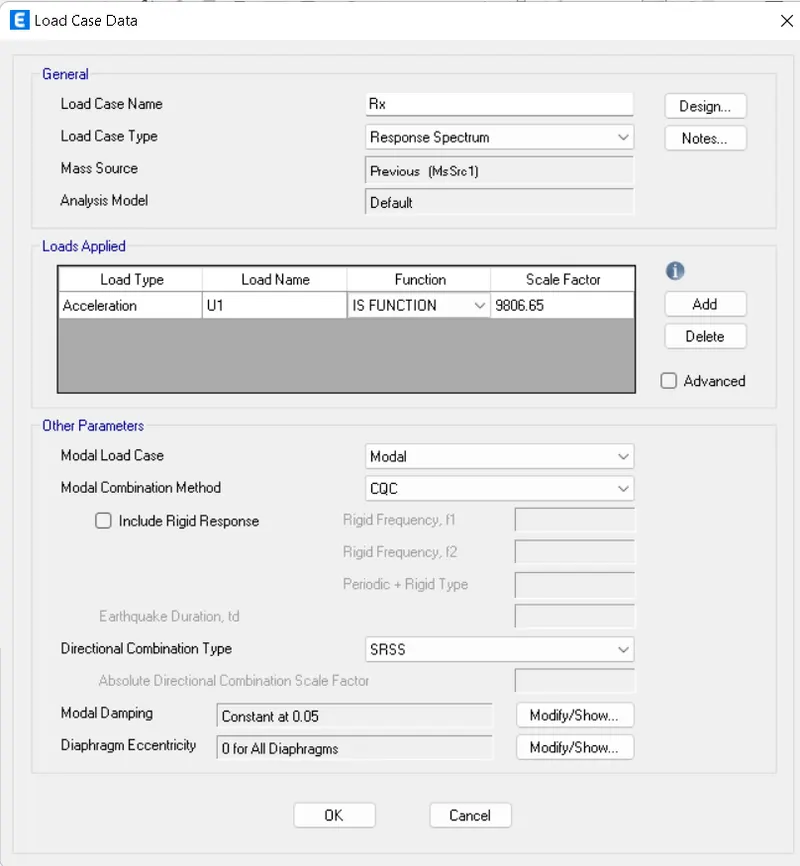
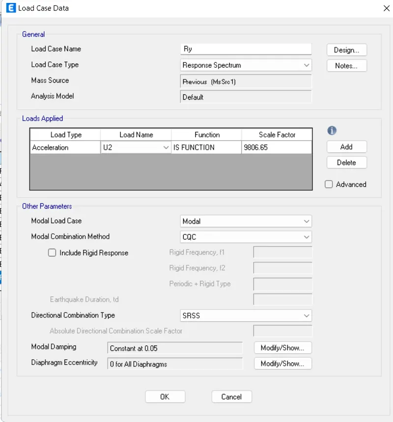
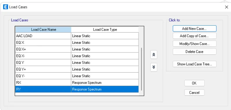
- Now go to Define and got ot the load pattern.
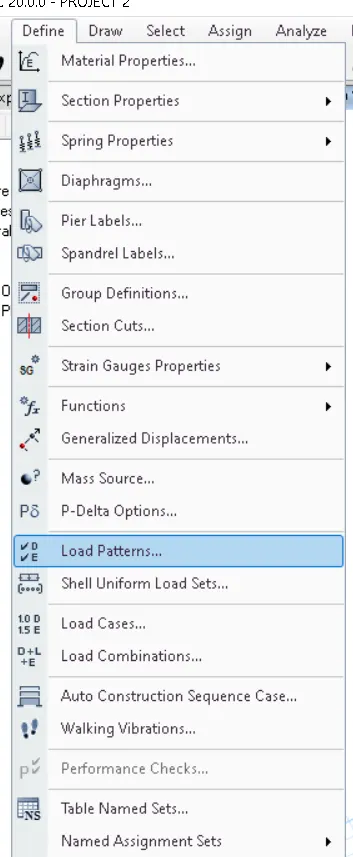
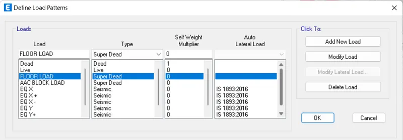
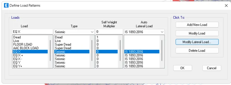
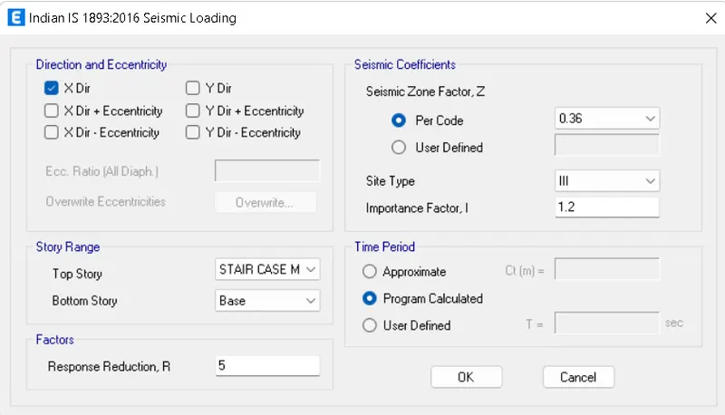
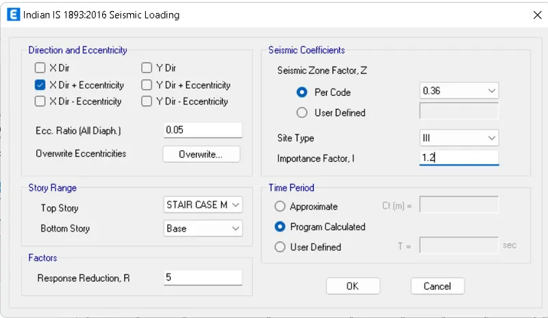
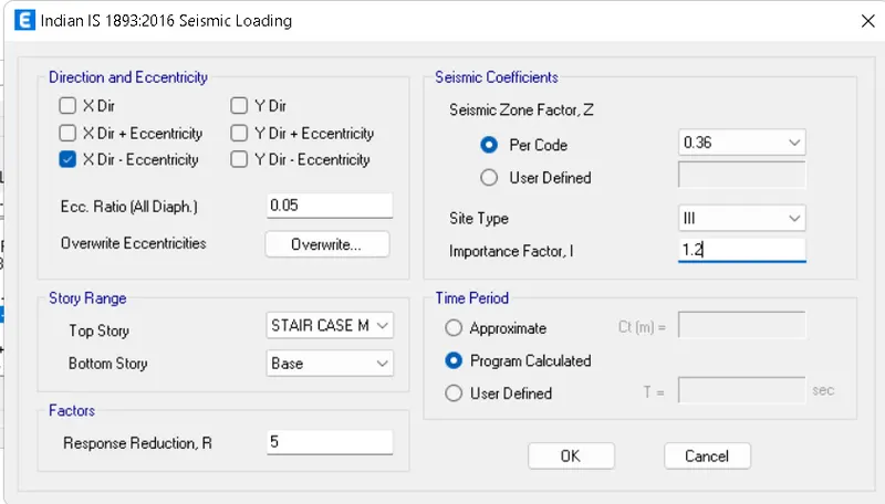
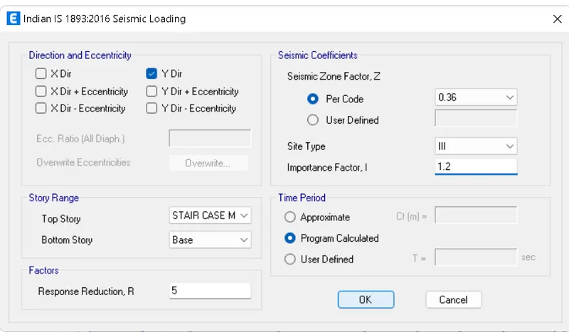
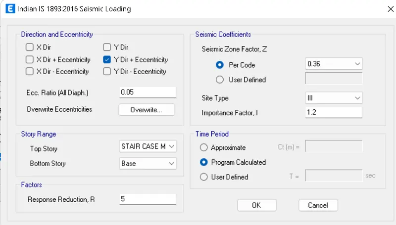
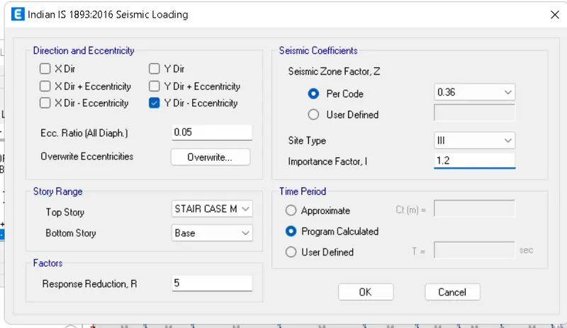
- Now go to Define < Load Combination
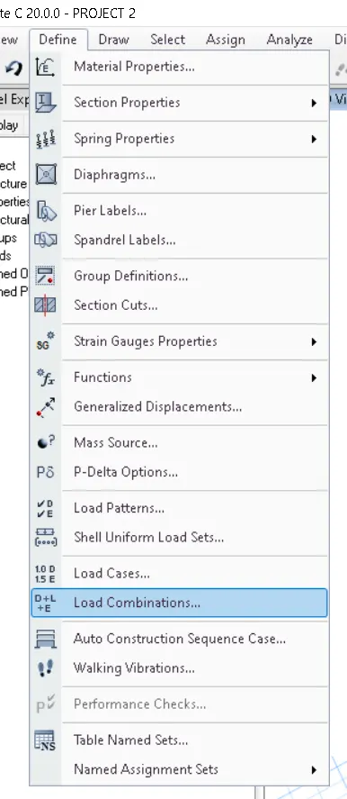
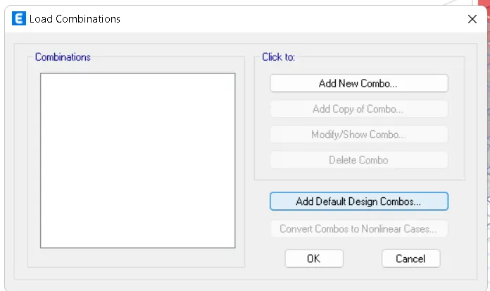
- Nowclick on Add Default Load Combination
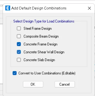
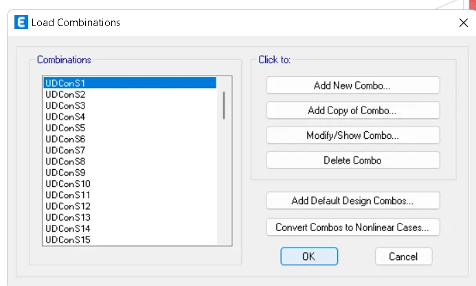
- select Concrete Frame Design And Concrete Shear wall Design ans tick to Convert to user combination.
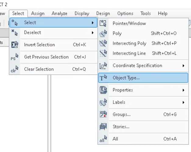
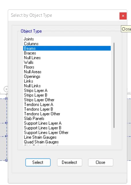
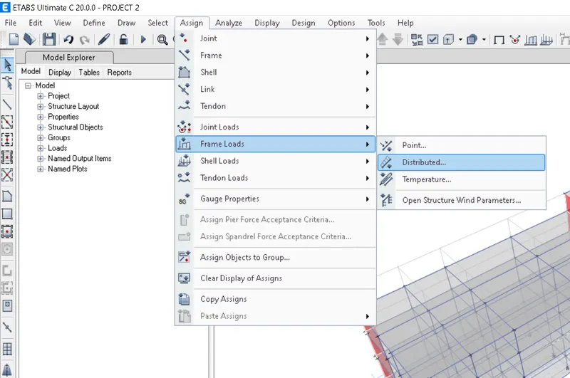
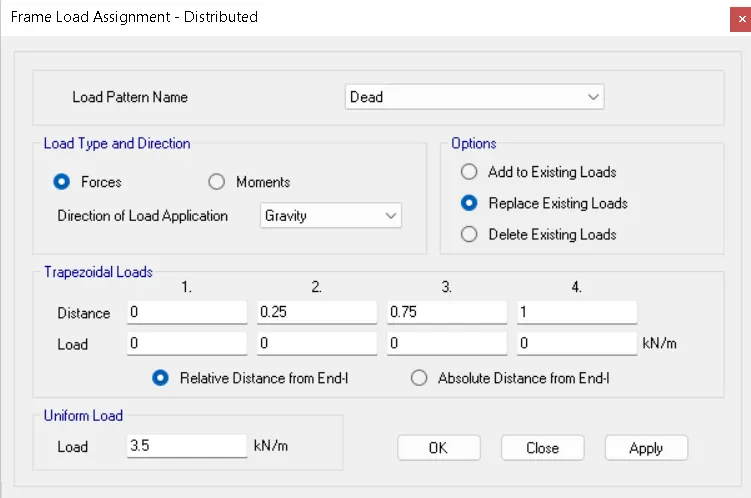
- AAC load of 3.5 kN/m since the aac blocks are used.
- Go to Assign < Frame Load < Distributed Load
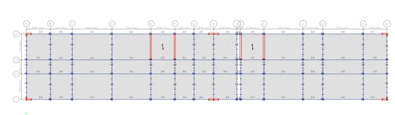
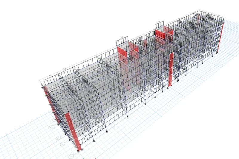
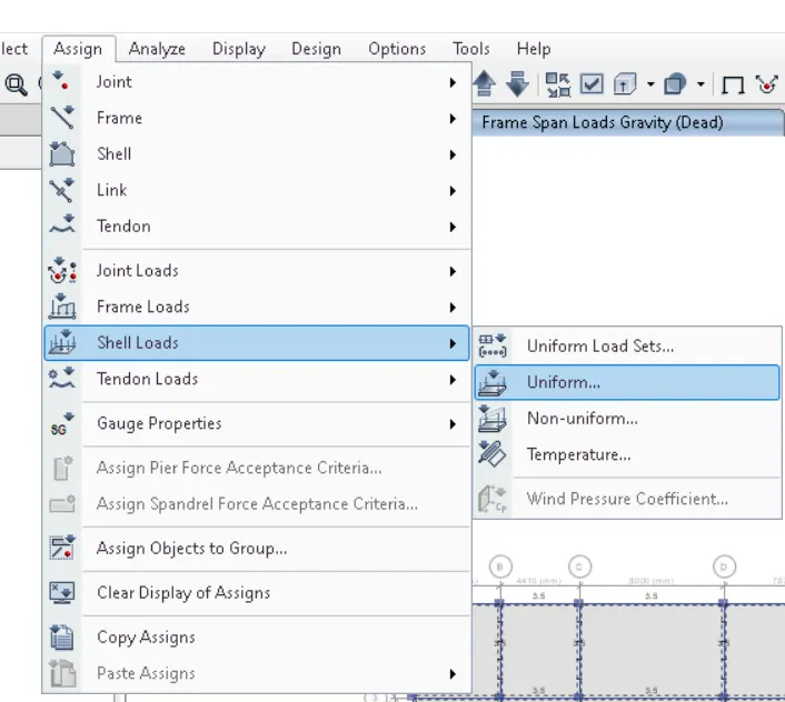
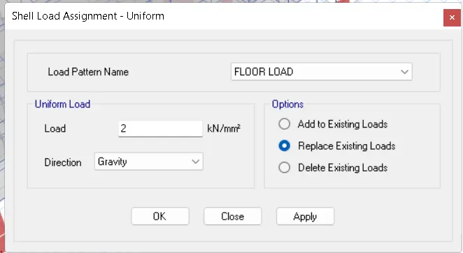
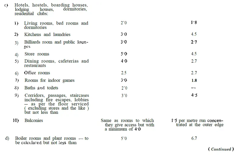
AS PER IS 1875 PART 2
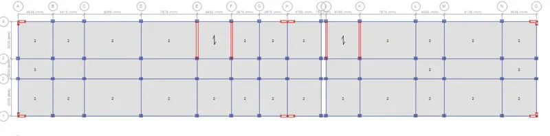
Live load at the roof floor needs to be reduced hence 2 kN/m is applied.
Assigning 2kN/m^2 live load for Rooms And Toilets
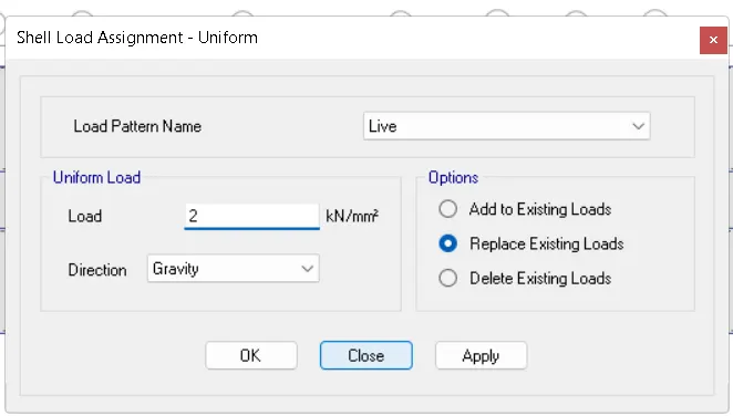
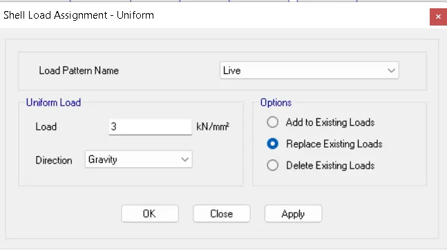
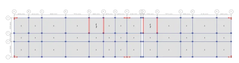
Assigning 3kN/m^2 live load for Staircase and Lobbies
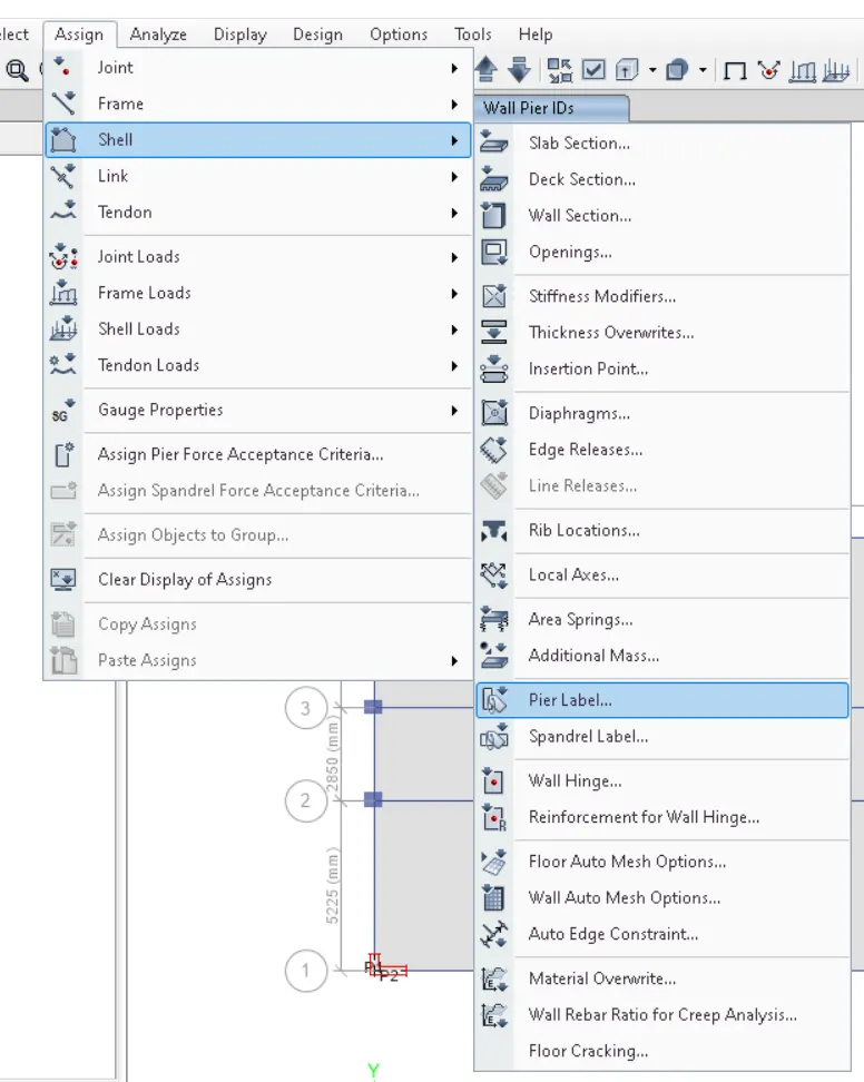
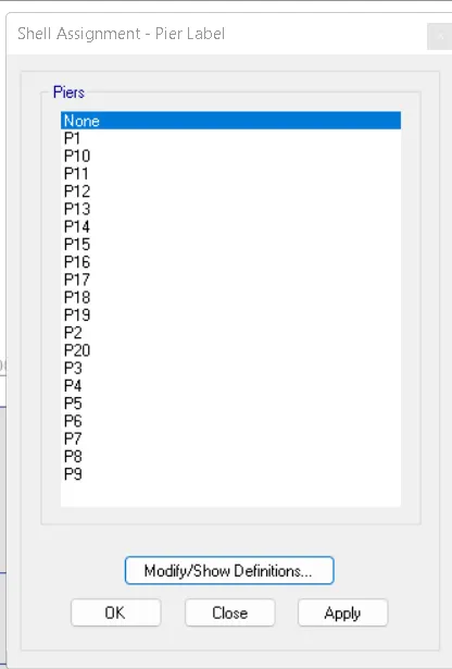
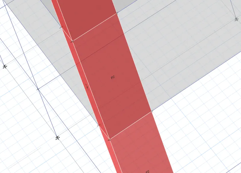
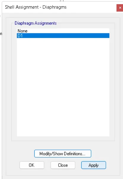
Go to assign < shell < select piers lebel
- And select all the floors and apply diaphragm D1
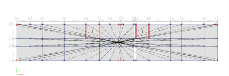
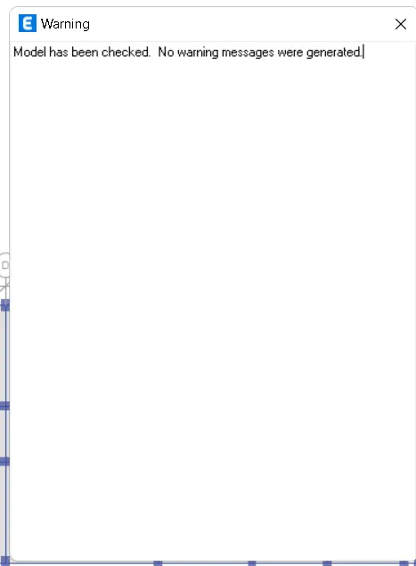
- Now check the model if there are any warning correct it and run the model.
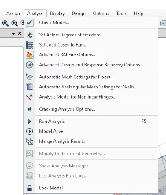
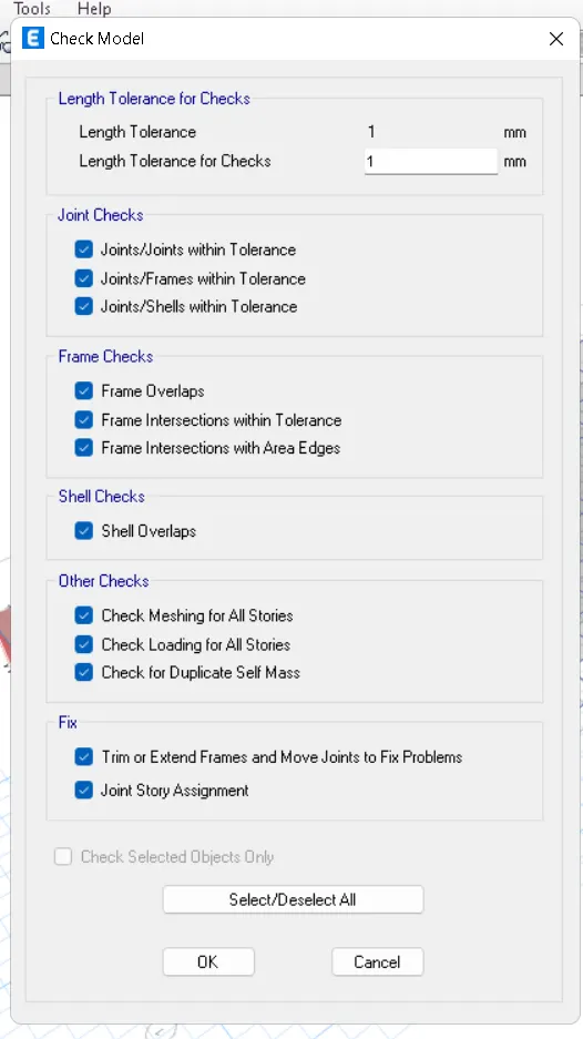
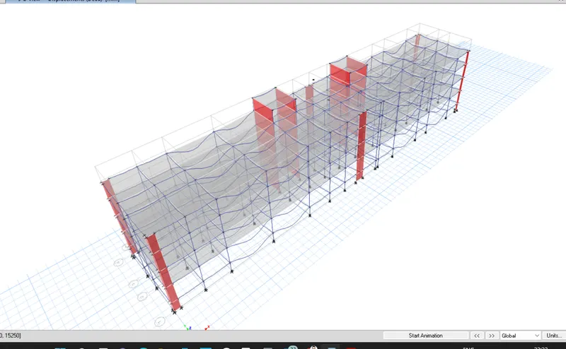
- Now check the model if there are any warning correct it and run the model.
- Go to analyze < Check Model

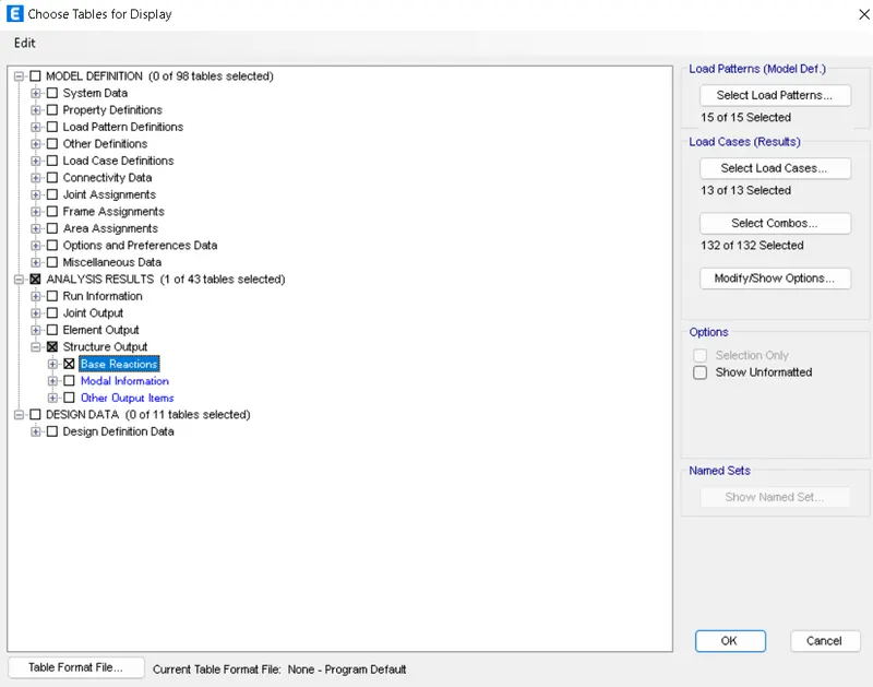
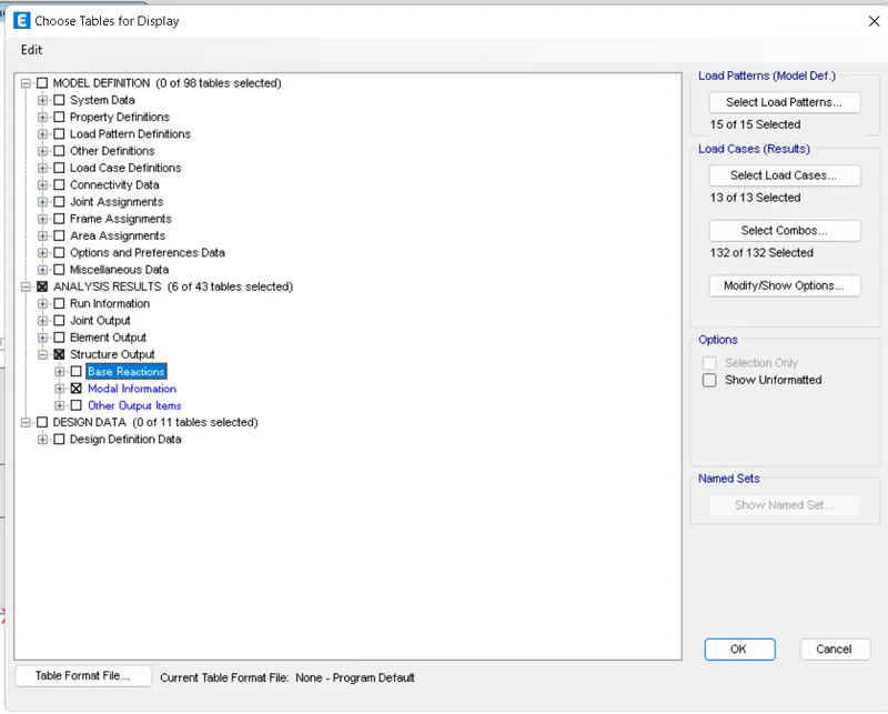
Go to Display < Show Table
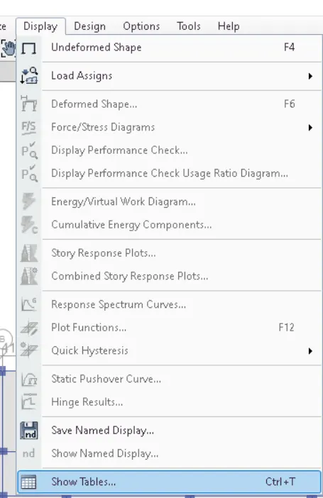
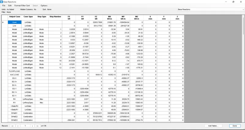
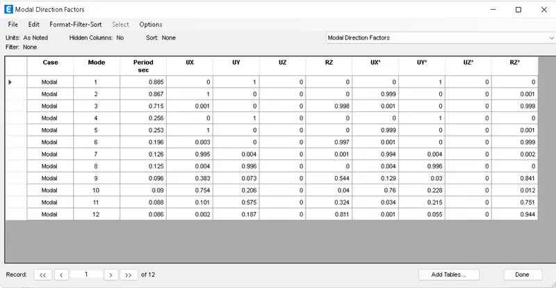
Go to Analysis result < Structure output < Base Reaction < Click ok
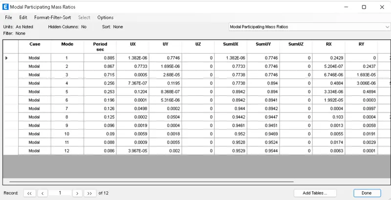
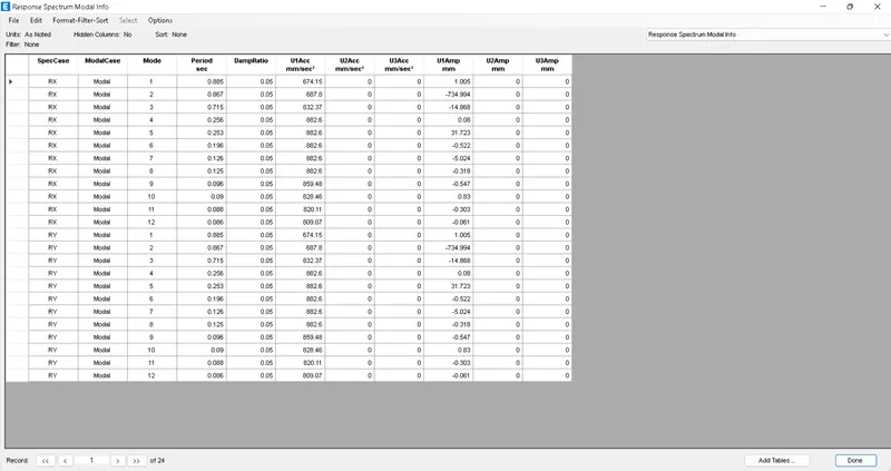
- Now Click on Concrete frame Design and Check.
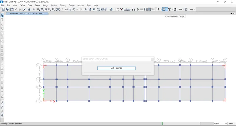
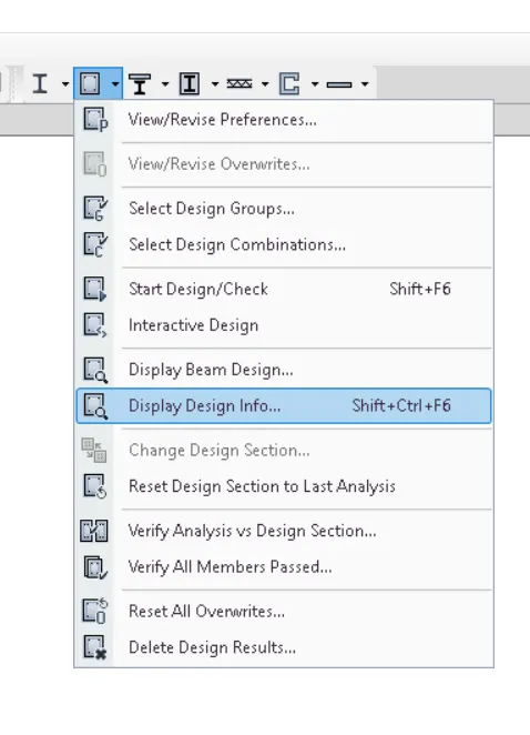
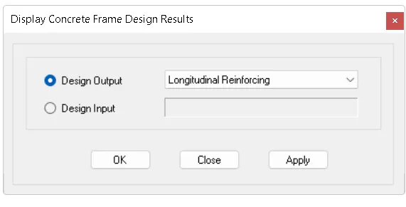
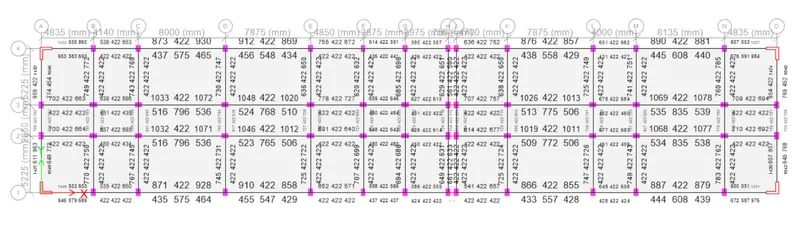
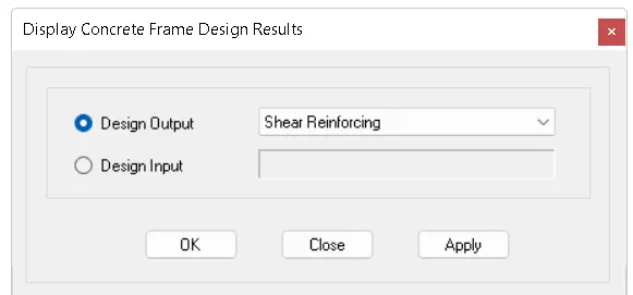
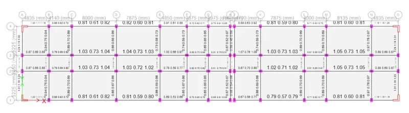
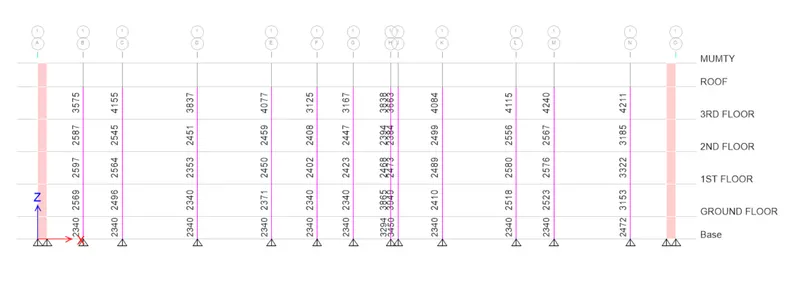
For Column 1A Area of Reinforcement
Area of 25 mm Dia bar =490
Area of 22mm dia bar= 380
Area of 20mm dia bar =314
3575mm^2 = 3040/380= 8 nos. of 22mm dia
490x2=980mm
2 Nos of Additional Bar of 25 mm Dia
- Now go to File < Export
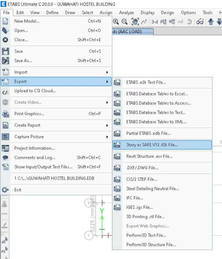
- Now Importing the safe file SAFE SOFTWARE
- Now open the safe Software
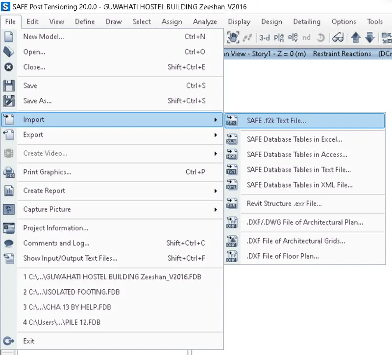
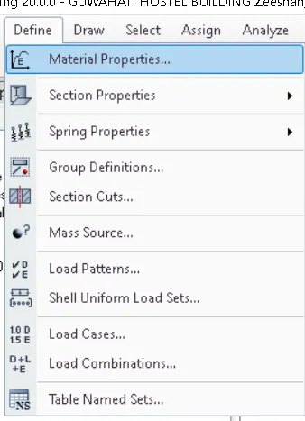
- Now go to Define and assign the Material properties
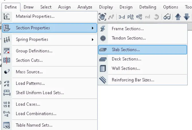
Again go Define < Go to section Properties < Go to Slab properties.
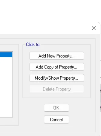
Click to Add New Properties
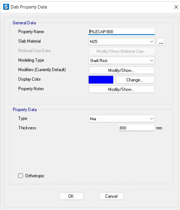
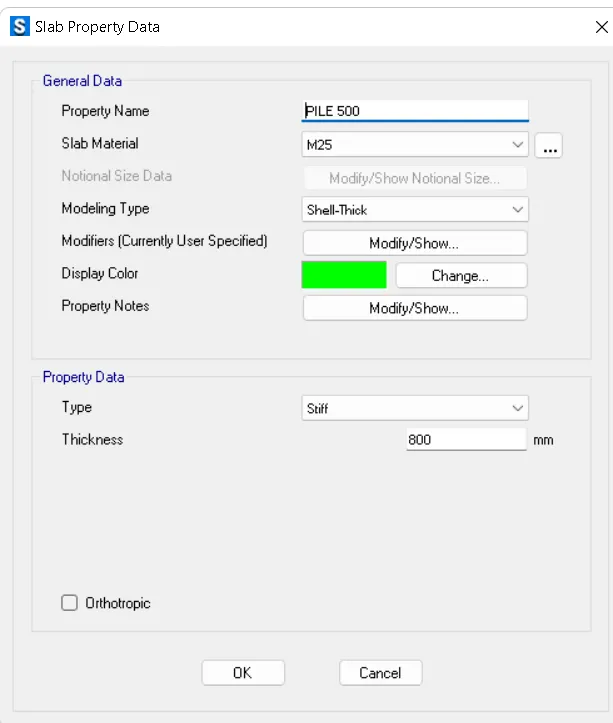
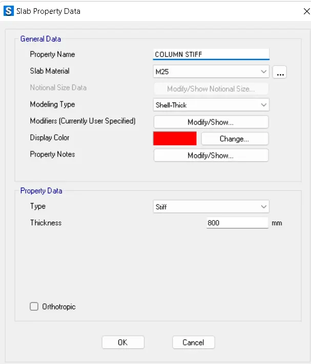
- Now go to load Pattern.
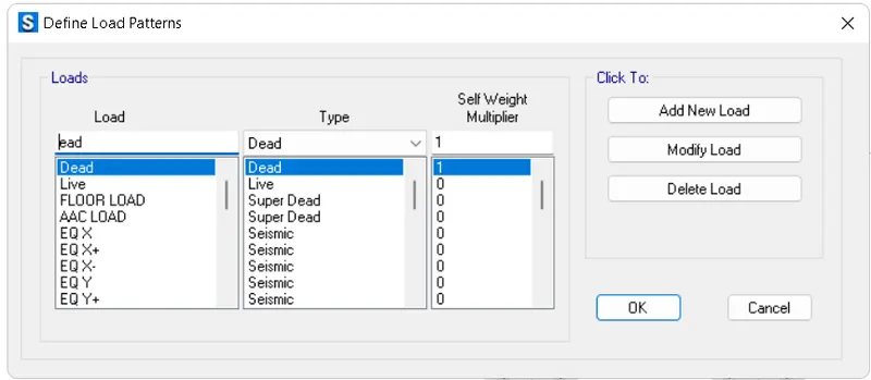
- A tab will appear then click on the story as base and select the loads and loads from above click on the combination click ok,
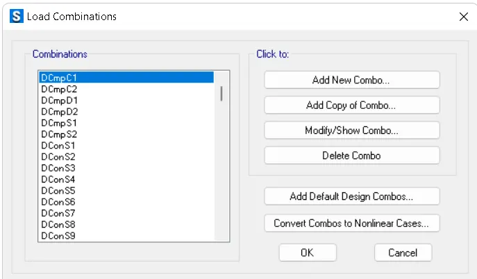
- Now Addd load combination to default
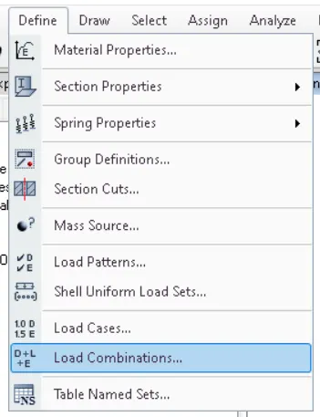
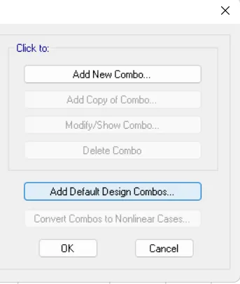
and all the load ccombination will apperar
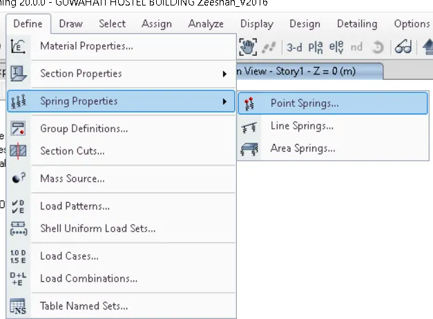
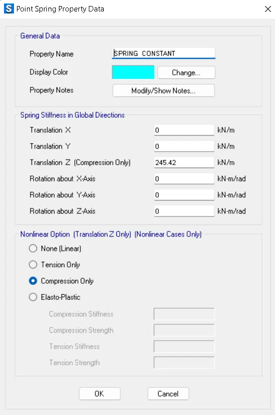
K=EA/L
E=5000(fck)^0.5=5000(25)^0.5=25000 N/mm^2
Area of pile =22/7*d^2=3.142*(500)^2/4=196375m^2
L-800mm
K=25000*0.7855/0.08=245468.75 N/m==245.46 KN/m
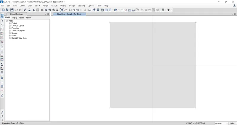
- First we draw a pile cap using point
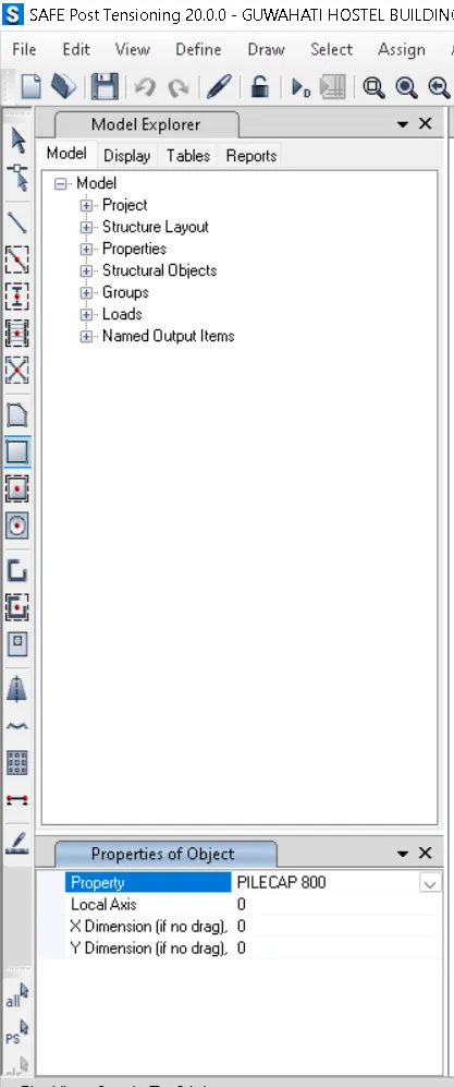
- Then we Add Pile Of 500mm Dia

- Number of piles=Total Axial load/pile capacity=(1.5DL+1.5LL)/280= numbers
- Spacing of the piles as per clause number 6.6.2 of IS 2911 the spacing between the piles =3 dia of the piles =3*500=1250mm
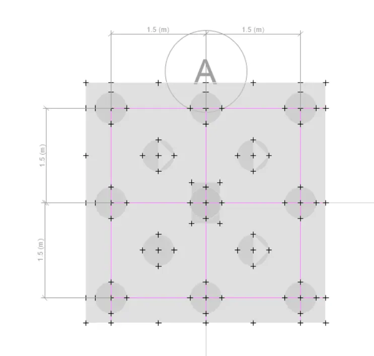
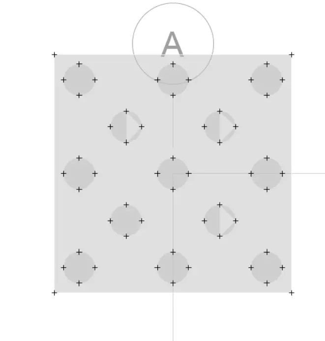
- then we assign column
-
Column of size:- 450mm *600 mm & 600mm*450m m
pile has a load carrying capacity of 280kN
Pile length-16 m and dia of pile -500 mm
Safe Bearing Capacity-150kN/m^2
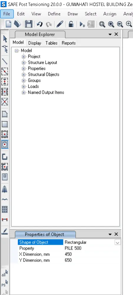
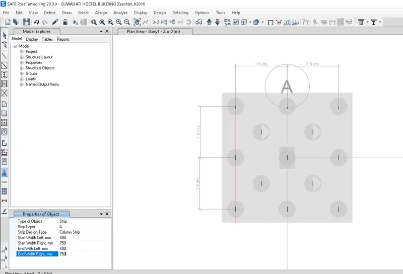
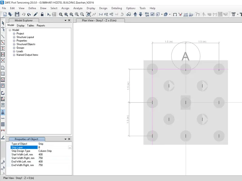
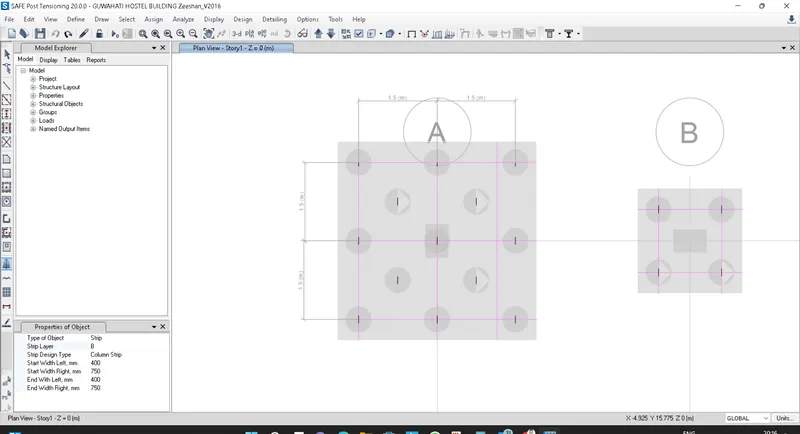
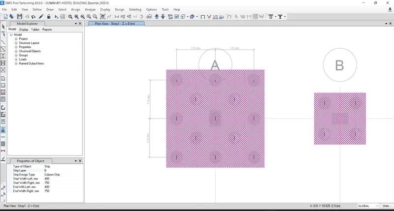
- Go to draw design strip
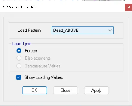
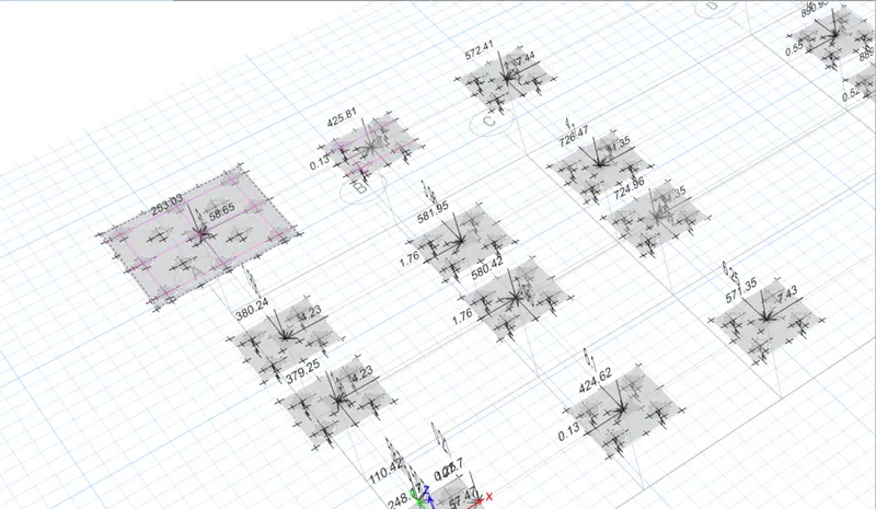
- Go to dispay click on the show loads select dead above and live above the values will be appeared.
- Now go to Display < Load case < Joint
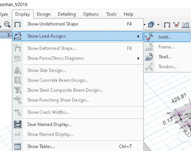
- select dead Load above and click ok
- live load above
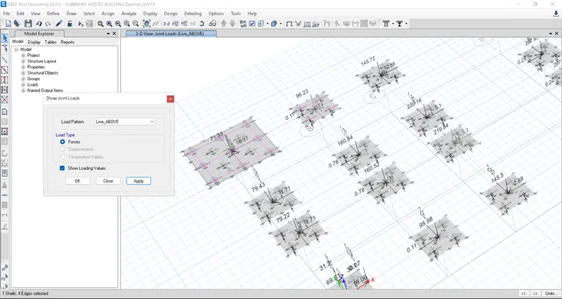
Now we can Run the Model Analysis
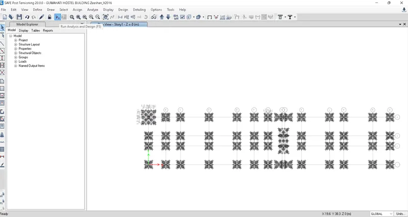
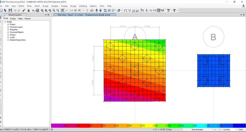
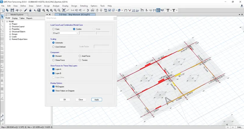
Now go to Display Strip Force And select Combination
Now go to display < show Shear Punching Display
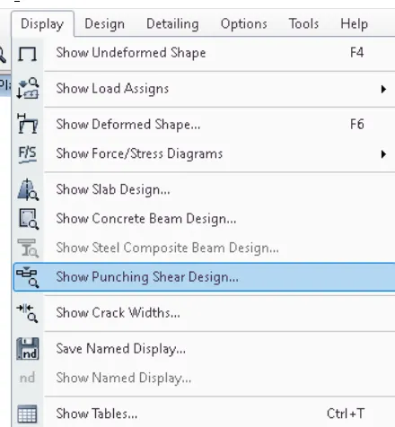
Since Punching shear is less than 1 hence it is ok .
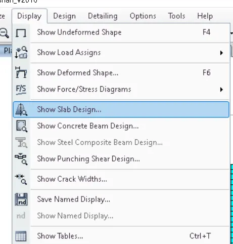
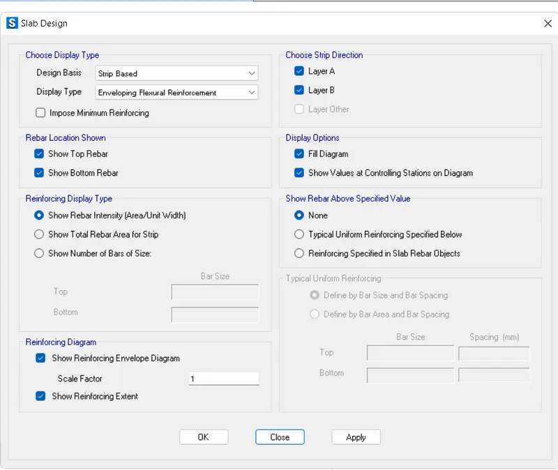
- Again go to Display < Show slab Design
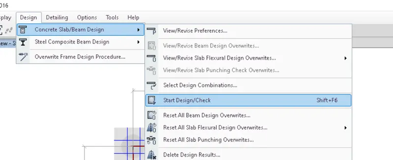
- Go to Design < Concrete Slab/Beam Design < Start Design check
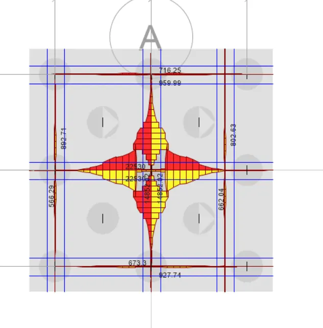
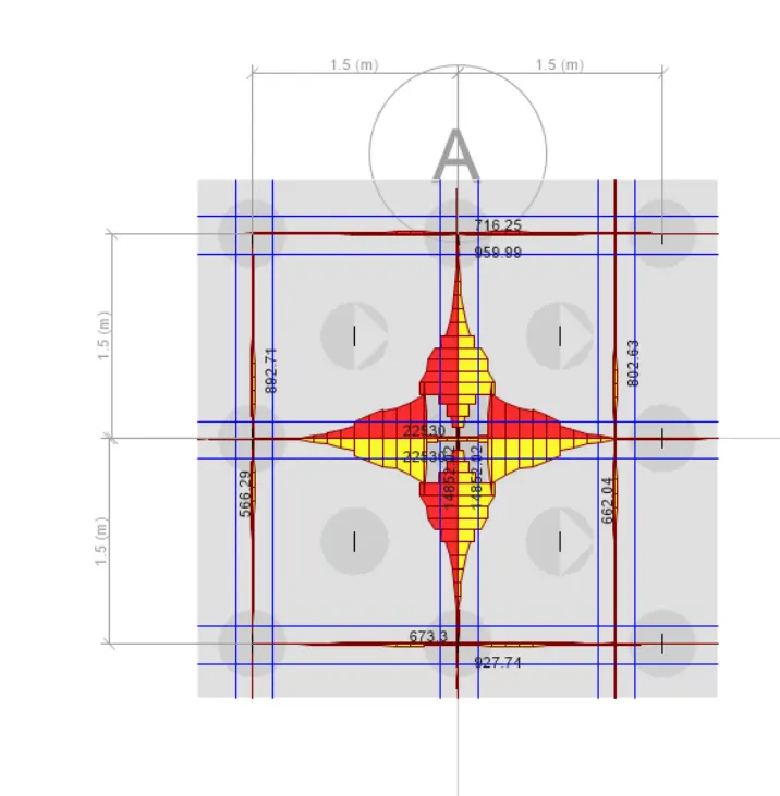
Middle Layer X DIRECTION MIDDLE STRIP
maximum Reinforcement was
For Top:- 22530 mm^2/m=22530/3.3=6827.27 mm^2=22nos. 20 mm dia are provided
For Bottom-22530 mm^2/m=22530/3.3=6827.27 mm^2=22nos. 20 mm dia are provide
Middle layer Y direction
maximum Reinforcement was
For Top:- 14852.02= 14852.02mm^2/3.3= 4500.61 mm^2=15nos of 20 mm dia are provided
For Bottom-14852.02= 14852.02mm^2/3.3= 4500.61 mm^2=15nos of 20 mm dia are provided