Project 2_Creating a 3D rendered model for a Residential Building in AutoCad
AIM: To Create a 3 dimensional model of the residential building with a rendered view.
INTRODUCTION: A 3 dimensinal model of the residential building with a render view is drawn using autocad software by considering all necessary commands. The detailed explanation of the project is as follows.
PROCEDURE:
- First step of any drawing in autocad is to set the UNITS(UN) for that drawing.
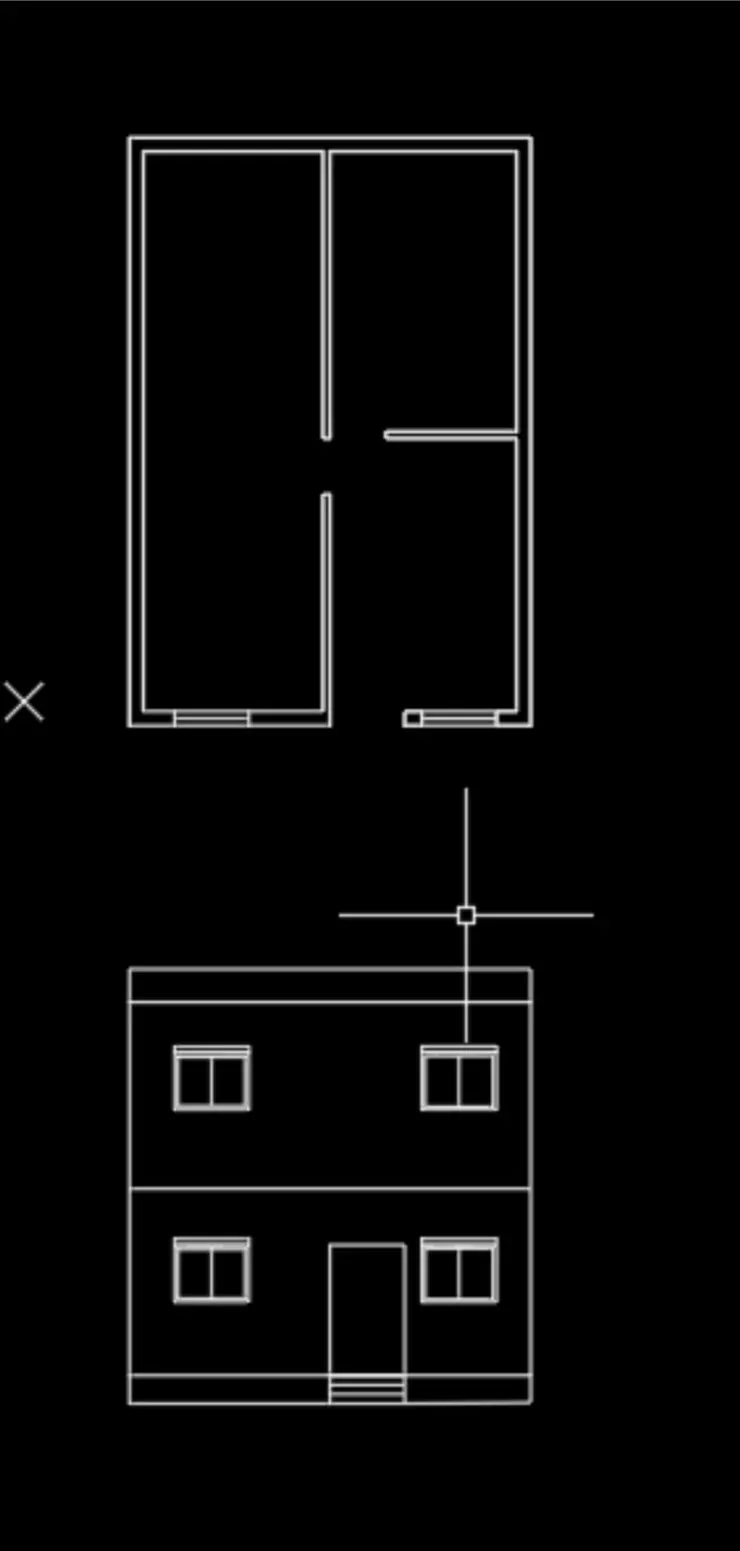
- In order to create a 3D model first we need to draw an 2D model.
- For this project I am considering a 2D model which i have drawn inn challange-7.
- Now open challange-7 and go to 3D modellinng which is at the right bottom.
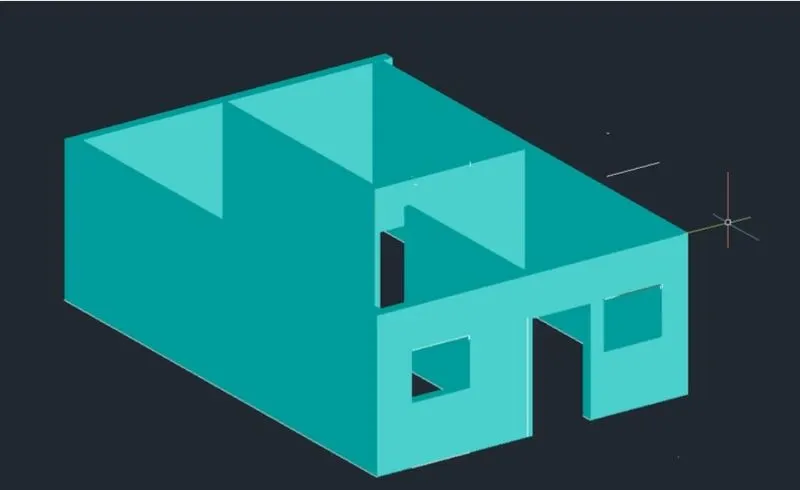
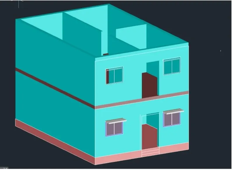
- Now the first step is to Make wall portions as surface by using command (REG) FOR REGION or (BO) BOUNDARY.
- After creating the wall surface now extrude(EXT) the walls up to a desired height. We can also extrude the wall by using PRESSPULL option.
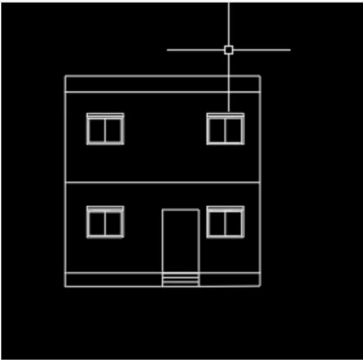
- Now its time to create a windows and doors. Create a (REC) Rectangle on the window and extrude it to a silt height.
- Now using UCS command place ucs at the top of the wall where the window is extruded at silt level so that we can draw a rectangle and extrude it from top which makes a opening in the wall then it will be easy to place a winndow.
- Simillarly repeat step-7,8 to create opening for doors.
- After that select the window which is created in 2D and Rotate(3Drotate) it in Z-axis.
- Before That we will create LAYERS(LA) to show difference between frame, mullions,glass etc.
- After creating layers, make frame layer to current and select the frame portion of the window by BOUNDARY(BO).
- If it creates that layer to entire window then use SUBSTARCT(SUB) to substract the unwantwed layer.
- Create mullions and glass in the same manner. Mkake sure that the paticular layer is on before drawing.
- Use above method for doors.
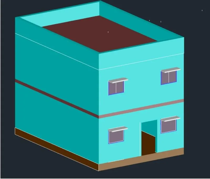
- Now it's time to place windows and doors in the wall openings which we have created earlier use copy(CO) command to it.
- We will create a plinth level so first we will turnoff the all layers by LAYOFF command. draw rectangle over the plan and make a copy of it take offset and make sufrace of it and extrude it to desired height.
- copy it and place it below the wall which we have created.
- Similarly using that rectangle create floor and place in the plan
- Copy the entire plan to make different floors.
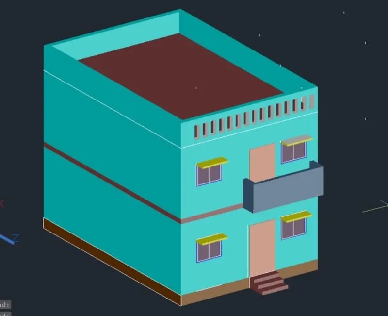
- If we want to create sajjas any additional elements like balconies just use UCS and place it on the surface where we need to create and draw rectangle ans just extrude it.
- Now 3D model is created.
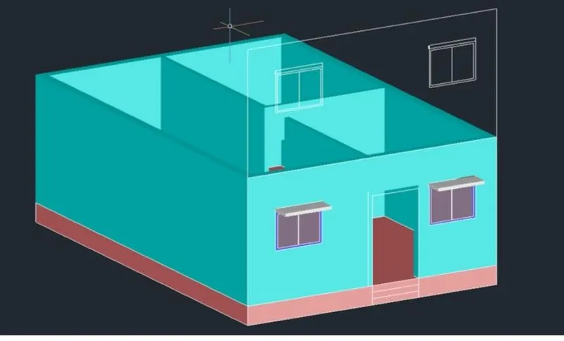
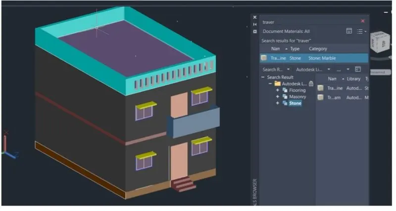
- Now go to VISUALIZE tab then materials select it add different materials for different elements and place that materials over the selected elements like walls, floors etc.
- For camera view first create a cylinder up to desired height where camera need to be placed select camera option in Visualize tab and place it over cylinder which is created. We can use multiple camera option in the simillar way.
- The last step is to do RENDERINNG. Go to rendering option in the visualize tab and select backgrounds and we also have different options like render duraration lights and materials.
- Last step is to go to render window it so that it diaplays the plan in the render view then save it.