Project 2_Creating a 3D rendered model for a Residential Building in AutoCad
| PROJECT 2 : Creating a 3D rendered model for a Residential Building in AutoCad |
- Aim :- To draw the 3D residential building and to create the rendered view
- Introduction :-
The general commands used for drawing the building is as follows :
- Line
- Polygon
- Rectangle
- Circle
- Erase
- Copy
- Trim
- Offset
- Extend
- Move
- Rotate
- Dimension
- Text
- Fillet
- Extrude
- 3D Rotate
Etc.
The dimensions:
- External and Internal wall – 230mm thick
- For Staircase : - Treads : 250 mm, Rise : 165mm
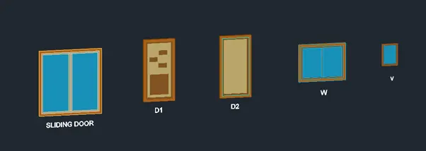
- W – 1200 X 1500
- V – 700 X 500
- D1 – 1000 X 2000
- D2 – 900 X 2000
- All the dimensions are in mm
- Procedure :-
- Click on AutoCAD application and open this application
- Type QNEW in command bar and enter
- Select default setting as Metric
- In default setting click on use a wizard and in that advance setting and set unit as decimal and precision as 0 and press Next
- Set Angle as Decimal Degree and precision as 0 and click next
- Set Angle Measure as EAST and press NEXT
- Set Angle Direction as Counter-Clockwise and press NEXT
- Set Area by providing Length as 50m and Width as 50m
- Press finish
- Keep ortho, Object snap >ON
- Keep Snap and Grid > Off
- Un+enter
- Type > Decimal, Precision > 0
- Units to scale inserted content > milimeter
- Enter
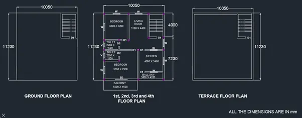
Steps to draw the Plan
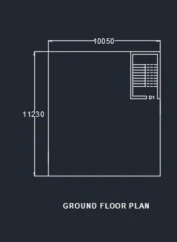
- Take the line command
- Specify first point > click anywhere on the sheet
- Specify next point > type 10050 > Enter by keeping curser rightside
- Specify next point > type 11230 > Enter by keeping curser upside
- Specify next point > type 10050 > Enter by keeping curser Lefttside
- Specify next point > type 11230 > Enter by keeping curser downside
- Enter
- Take the offset command
- Specify distance > 230
- Select object > Right side vertical line
- Specify distance > 2460
- Select object > Right side vertical line
- Specify distance > 2690
- Select object > Right side vertical line
- Specify distance > 230
- Select object > Top side Horizontal line
- Specify distance > 4000
- Select object > Top side Horizontal line
- Specify distance > 4230
- Select object > Top side Horizontal line
- The stair case hall is ready
- Take offset command
- Specify offset distance > 900 to show landing width
- Select object > Top horizontal
- Specify Offset distance > 250 to show the tread
- Select object > Landing line
- Continuously provide the offsets for tread as per design requirement
- By using line command divide the staircase tread in two parts to show the different flights
- The ground floor plan is ready
- Take copy command
- Select the whole ground floor plan to prepare the First and Secon Floor Plan
- By Keeping ORTHO mode On, Copy the entire drawing beside it
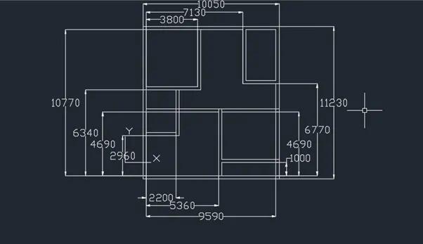
- Take offset command
- Specify offset distance > 230
- Click on all the lines on the screen > Keeping curser inside the lines to show the wall thickness
- Take the offset command and provide the offset as per shown below
- Also give offset to all the last offsets of distance 230 to show the wall thickness
- Trim and erase the unwanted lines
- Left the space for doors as per requirement
- Use the line command to provide the windows
- Use the copy and rotate command to provide the windows
- Take a line and offset command to prepare the whole plan
- Trim and erase the unwanted lines
- Use the dash line to provide the chajja
- Take the rectangle command
- Specify first corner point > Anywhere in the drawing
- Click > Dimension
- Specify length > 230
- Specify width > 230
- Enter
- Copy this rectangle to show the columns
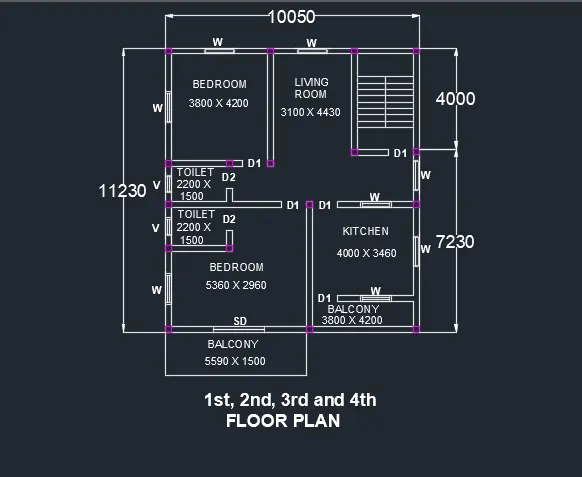
- To create the text
- Click on Annotation tab >multi line
- Manage textile > New
- Style name as > Project > OK
- Font Name > Arial
- Height > 300
- And press set current
- Use multiline text
- And fill the required text in drawing as shown below
- Click on ANNOTATION tab
- Click on Dimension
- Click > Manage dimension style
- Style name > Project
- Set the characteristics of dimensions as
- Select the yellow colour for the dimension style and extension line
- Select arrowhead size as 200
- Select the text as Cyan colour
- Select Text Style > Project
- Text Height > 300
- Then select linear dimensions
- Provide the required dimensions
- The 1st, 2nd, 3rd and 4th floor plan is ready
- To create the terrace floor plan
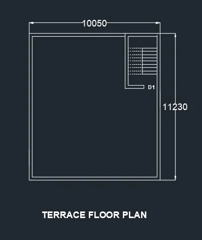
- Copy the ground floor plan
- By using offset command
- Provide the wall thickness of 230 to show the parapet thickness
- Provide the dimensions as per requirement
- The terrace floor plan is ready
3D Setting
- Select workspace switching > 3D Modelling
- Select Visual style control > 2D Wireframe
- Use the 3D orbit command to set it in proper position
Selection of Layers
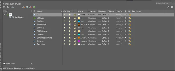
- Click on layer properties
- Click on new layer
- Give the layer name > 3D Wall
- Turn the layer ON
- Set Unlock
- Slect layer colour > Cyan
- Similarly, use this above process to provides the layer
- The layers which are assigned are shown in below fig
Steps to draw 3D staircase
- Set the current layer as > Staircase
- Take a line command
- Specify first point > Anywhere in the drawing
- Specify next point as > @0,0,165 > Enter
- Specify next point as > @250,0,0 > Enter
- Specify next point as > @0,0,165 > Enter
- Specify next point as > @250,0,0 > Enter
- Specify next point as > @0,0,165 > Enter
- Specify next point as > @250,0,0 > Enter
- Specify next point as > @0,0,165 > Enter
- Specify next point as > @250,0,0 > Enter
- Specify next point as > @0,0,165 > Enter
- Specify next point as > @250,0,0 > Enter
- Specify next point as > @0,0,165 > Enter
- Specify next point as > @250,0,0 > Enter
- Specify next point as > @0,0,165 > Enter
- Specify next point as > @250,0,0 > Enter
- Specify next point as > @0,0,165 > Enter
- Specify next point as > @250,0,0 > Enter
- Specify next point as > @0,0,165 > Enter
- Specify next point as > @900,0,0 > Enter
- Enter
- Provide the weist slab of 100 by using line and offset command
- Take the boundry command
- Pick internal point
- Select the internal portion of staircase
- Enter
- Visual style control > Shaded
- Take extrude command
- Extrude the stairs at 1115
- Take 3d Rotate command
- By using this command put the staircase as per direction
- Select all the staircase
- Take copy command
- And place it in proper position to create the next flight
- Use the 3D rotate command to place the last flight of the staircase in proper position
- Take a circle command
- Specify centre > At railing position
- Click > Diameter
- Specify diameter > 50
- Enter
- Extrude that circle at a height > 900
- Copy that cylinder and place it in a proper position
- Use the line and sweep command to draw the horizontal handgrill
- The staircase is ready
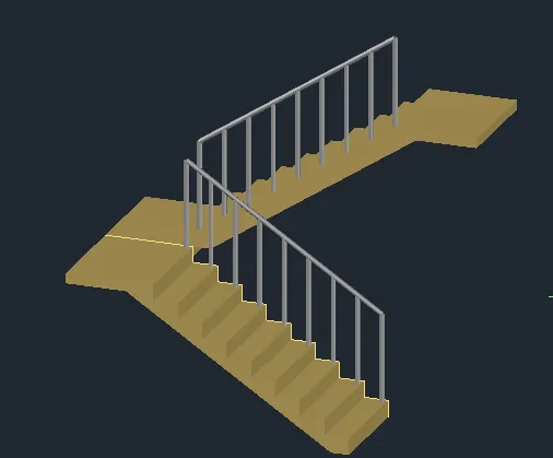
- To set the above view
- Go to > Visyalise tab
- Click > View Manager
- One dialogue box will open
- Click > New
- Specify View name > Staircase view
- Enter
- Set current
- Enter
- The Staircase view is saved
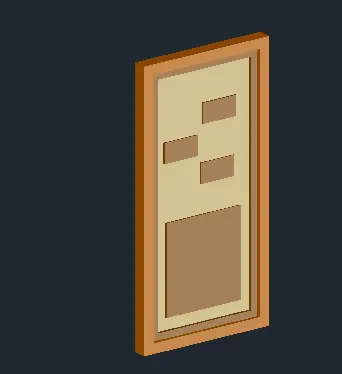
Steps to create the 3D Door and Windows
- Change the layer as per requirement
- Take the rectangle command
- Specify first corner point > Anywhere in the drawing
- Click > Dimension
- Specify length > 1000
- Specify width > 2000
- Take offset command to show the door frame
- Take offset distance > 75
- Select object > Rectangle
- Again take offset command to show the mullion
- Take the offset distance > 50
- Use the region command and substraction command to make it 3D
- Take the extrude command
- Select object > Door frame
- Extrude it at a distance > 100
- Take the extrude command
- Select object > Mullion
- Extrude it at a distance > 50
- Take the extrude command
- Select object > Door
- Extrude it at a distance > 10
- Use the move command to set all the components in a proper manner
- Use the rectangle, extrude command to provide the architectural view
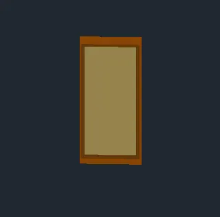
- Take the rectangle command
- Specify first corner point > Anywhere in the drawing
- Click > Dimension
- Specify length > 900
- Specify width > 2000
- Take offset command to show the door frame
- Take offset distance > 75
- Select object > Rectangle
- Again take offset command to show the mullion
- Take the offset distance > 50
- Use the region command and substraction command to make it 3D
- Take the extrude command
- Select object > Door frame
- Extrude it at a distance > 100
- Take the extrude command
- Select object > Mullion
- Extrude it at a distance > 50
- Take the extrude command
- Select object > Door
- Extrude it at a distance > 10
- Use the move command to set all the components in a proper manner
- Take the rectangle command
- Specify first corner point > Anywhere in the drawing
- Click > Dimension
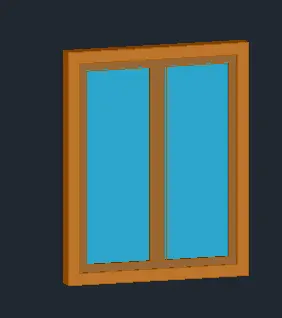
- Specify length > 1200
- Specify width > 1500
- Take offset command to show the window frame
- Take offset distance > 75
- Select object > Rectangle
- Again take offset command to show the mullion
- Take the offset distance > 50
- Use the region command and substraction command to make it 3D
- Take the extrude command
- Select object > Window frame
- Extrude it at a distance > 100
- Take the extrude command
- Select object > Mullion
- Extrude it at a distance > 50
- Take the extrude command
- Select object > Window
- Extrude it at a distance > 10
- Use the move command to set all the components in a proper manner
- Use the similar process to prepare all the Sliding door and ventilator
Steps to draw the 3D Building
- Copy the first and second floor plan
- Erase all the unwanted things such as text, dimensions etc. from the copied plan
- Change the corrent layer to 3D wall layer
- Take boundry command
- Pick internal point
- Select the internal portion of staircase
- Enter
- Visual style control > Shaded
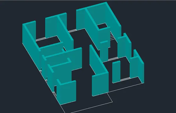
- Take extrude command
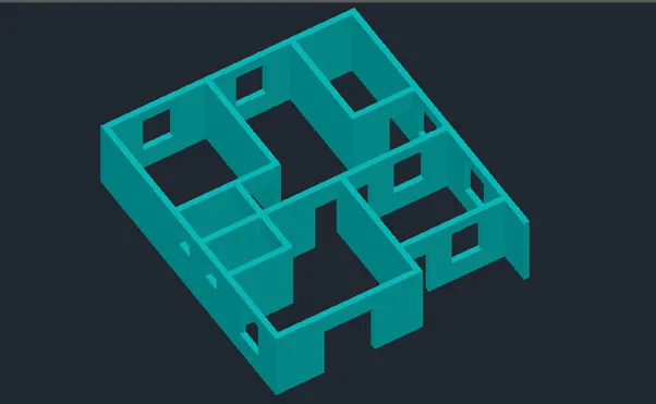
- Extrude the Wall at 2870
- It will shows the following result
- Take the ucs command
- Select any wall havng window
- Take a rectangle command
- Specify corner point > Corner of window
- Specify other point > Click on opposite corner point
- Enter
- Move that rectangle in Z-axis at height of 900 to show the window seal level
- Take copy command
- Copy theat rectangle in Zaxis at height of 1500
- Extrude both the rectangles and take union command
- Select the object > Wall and extruded part
- Enter
- Similarly by using this same process, provide the space for window as well as for doors and ventilators
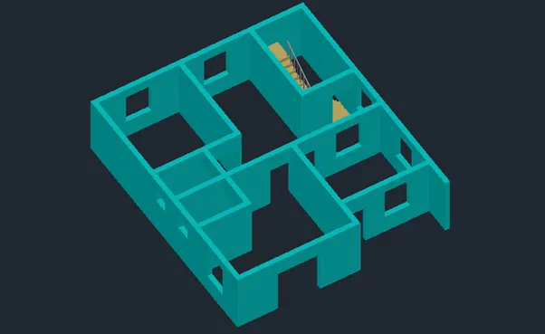
- Go to staircase view drawn before
- Use the copy command
- Copy that staircase in a building in proper way
- To set the above view
- Go to > Visualise tab
- Click > View Manager
- One dialogue box will open
- Click > New
- Specify View name > V1
- Enter
- Set current
- Enter
- The v1 view is saved
- Use the UCS command
- Copy all the respective doors and windows
- Place it in a proper position
- The first floor is ready
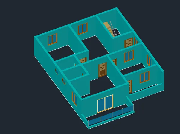
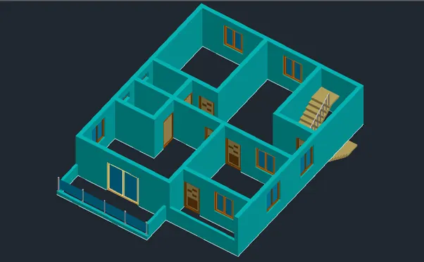
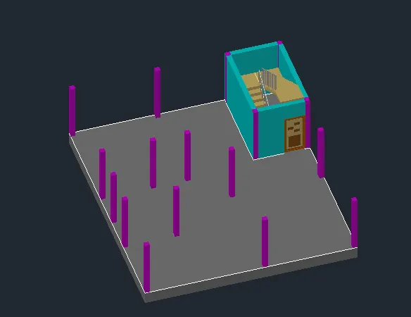
- Similarly use the above methods to create 3D of the Ground floor
- In 3D grund floor view, the colums are visible
- Take region command
- Select
- Use the extrude command to show its height
- From the staircase view copy the staircase and place it in a proper position
- To set the above view
- Go to > Visualise tab
- Click > View Manager
- One dialogue box will open
- Click > New
- Specify View name > GF View
- Enter
- Set current
- Enter
- The GF view is saved
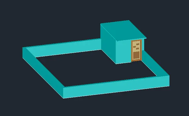
- Similarly use the above methods to create 3D of the Terrace floor
- To set the above view
- Go to > Visualise tab
- Click > View Manager
- One dialogue box will open
- Click > New
- Specify View name > TF
- Enter
- Set current
- Enter
- The TF view is saved
- Enter
- Take a rectangle command
- Specify corner point > Anywhere in the drawing
- Click > Dimension
- Specify Length > 10050
- Specify Width > 12230
- Enter
- Make it region
- Use the flooring material to rectangle
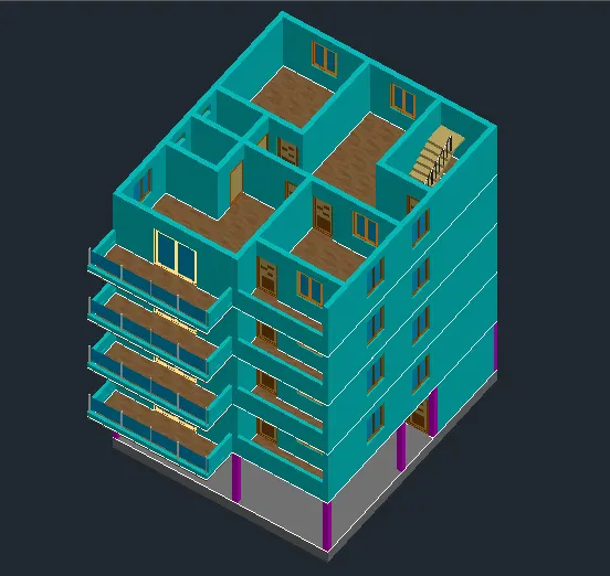
- Copy the first floor
- And place it above the rectangle flooring
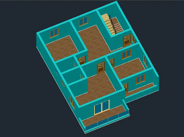
- Take copy command
- Select object > Select the above object
- Place it on the ground floor in proper manner
- Take move command
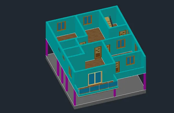
- Take Copy command and copy the second floor over the first floor
- Similarly put all the floors
- Enter
- Take a rectangle command
- Specify corner point > Anywhere in the drawing
- Click > Dimension
- Specify Length > 10050
- Specify Width > 12230
- Enter
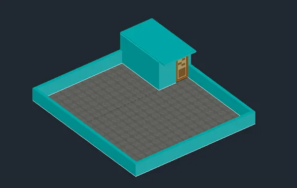
- Make it region
- Use the flooring material to rectangle
- Copy the Terrace floor
- And place it above the rectangle flooring
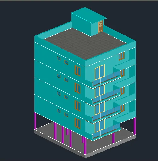
- Move this terrace floor
- Put it on the building
Steps to provide the material
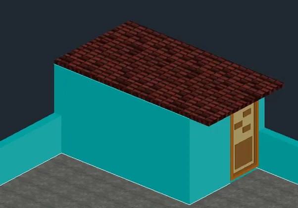
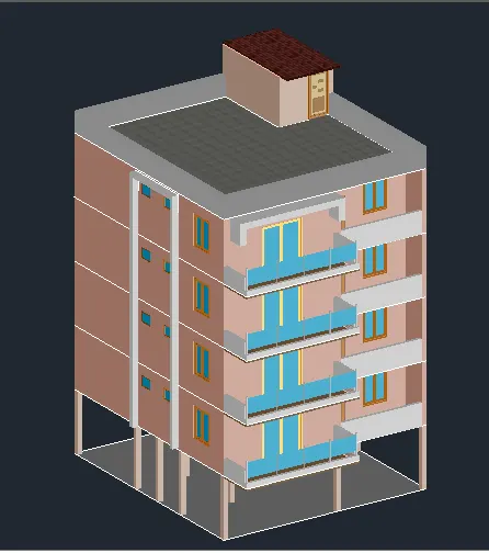
- Take material browser command
- Select Autodesk library > Roofing
- Select Roofing > Spanish – Red 3 > Add to material
- Selct the roofing part > Assign the material
- Enter
- Take material mapping command
- Use it in a proper way, to see material in appropriate manner
- Switch visual style control > Realastic
- The roofing material is ready
- Take material browser command
- Select Autodesk library > Wall paint
- Select wall paint > Pearl > Add to material
- Selct the wall part > Assign the material
- Enter
- The wall paint is ready
- Take material browser command
- Select Autodesk library > Wall paint
- Select wall paint > white > Add to material
- Selct the projection > Assign the material
- Enter
- Assign all the materials which are necessary
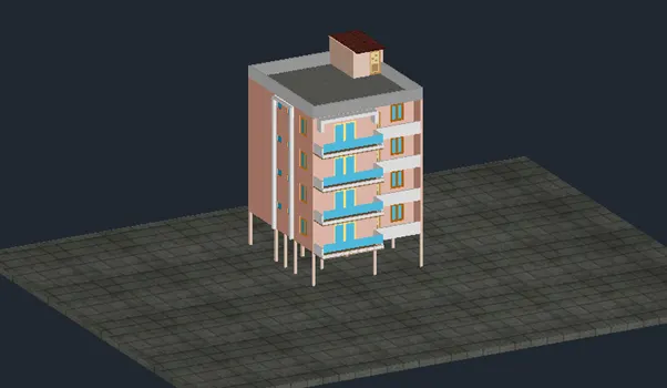
- Take rectangle anywhere in the drawing
- The rectangle should be more than the ground floor area
- Make it region
- Extrude it below > 100
- The wall paint is ready
- Take material browser command
- Select Autodesk library > Concrete
- Select Concrete > Block > Add to material
- Selct the rectangle> Assign the material
- Enter
- Move the building on that rectangle
Steps to set the Camera
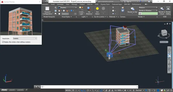
- Take a circle command
- Place it at left bottom corner
- Extrude it at height > 5000
- Click > Visualise > camera
- Name it as > Cam1
- Set target
- Delete the cylinder
- Click on the camera it will gives the following result
Steps to set the Distant light
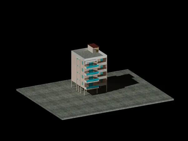
- Take a circle command
- Place it at right bottom corner
- Extrude it at height > 20000
- Click > Visualise > Create light > Distant light
- Name it as > Sun light
- Set target
- Set intensity > 100
- Delete the cylinder
- Take rr command to see the effect
- Save this image
Steps to set the exposure condition
- Select visualise tab > Render > Click dropdown
- Render environment and Exposure
- Select Environment > ON
- Click > Use custom Background > Gradient
- Select top colour > Blue
- Select bottom colour > White to represents the sky
- Enter
- Click on sun status
- Select time and date
- Date as
- Time as > 5:30PM
- Enter
- Click on > Render preset manager
- Render in > View port
- Render
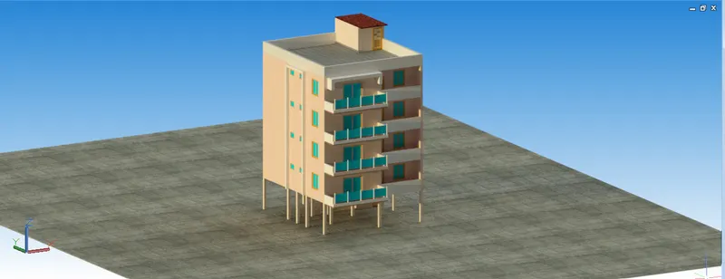
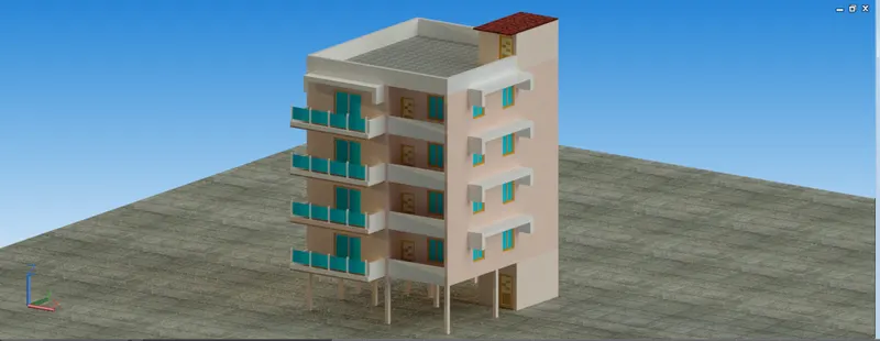
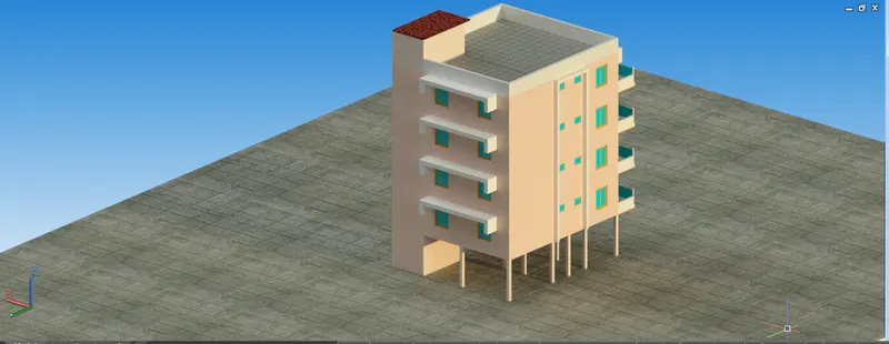
- The 3D model of residention building is ready with rendering views.
View 1:
View2:
View3:
- Result :-
- Plan :-
- 3D Staircase :-
- 3D Doors and Windows :-
- 3D Ground Floor :-
- 3D 1st, 2nd, 3rd and 4th Floor :-
- 3D-Terrace Floor :-
- 3D Residential building (without materials) :-
- 3D Residential Building (with materials) :-
- Rendere View 1 :-
- Rendere View 2 :-
- Rendere View 3 :-