Project 2_Creating a 3D rendered model for a Residential Building in AutoCad
CREATING A 3D RENDERED MODEL FOR A RESIDENTIAL BUILDING IN AUTOCAD
Aim:
To create a 3 dimensional model of the residential building with a rendered view in AutoCAD.
Introduction:
Rendering is a process of creating a raster image based on 3D objects in a scene. A renderer is used to calculate the appearance of the material attached to the object in a scene, and how lighting and shadows are calculated based on the lights placed in a scene.
Environmental and exposure settings can be adjusted to control the final rendered image. The basic rendering workflow is to attach materials to the 3D objects of a model, place user defined lights, add a background and start the renderer with the RENDER command.
Lights and materials can be added to a 3D model before a photorealisitic image is rendered.
Rendering quality can be changed by using the cameras, sunlight different types of lights like point light, spot light, distant light etc. Using these commands properly can improve the rendering to a great extent.
Procedure:
- Open the AutoCAD and go to 3D modelling.
- Initially set the units of the drawing as decimal (mm).
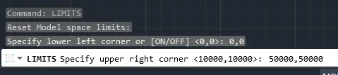
- Now, set the limits of the drawing:
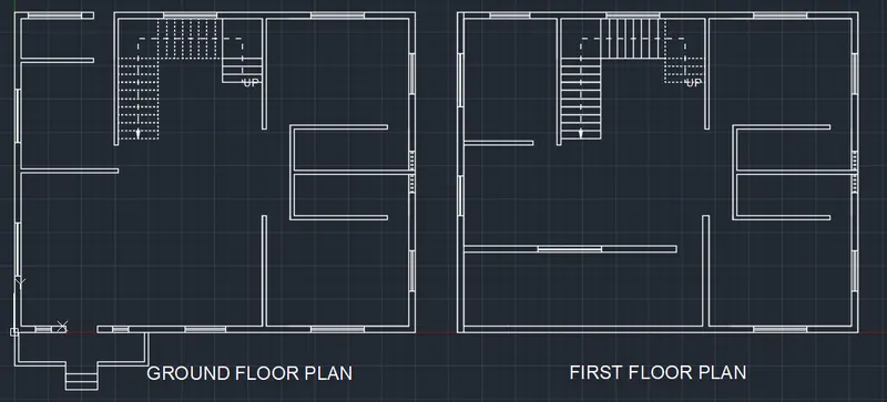
- Now create a 2D plan for a residential building with the help of commands like line, offset, trim etc.
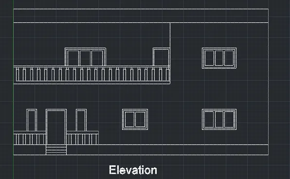
- Now, create the elevation of the same by using lines, offset, trim and other necessary tools in AutoCAD.
- Now, we have to create the 3D model of the same.
- For this move to 3D modelling workspace in the settings.
- Now, copy the plan separately.
- Then create different necessary layers like 3D walls, 3D windows etc.
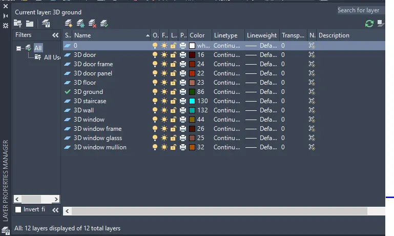
- Now, copy the first floor plan and create the boundary region.
- Then extrude the 3D wall leaving the space for the windows.
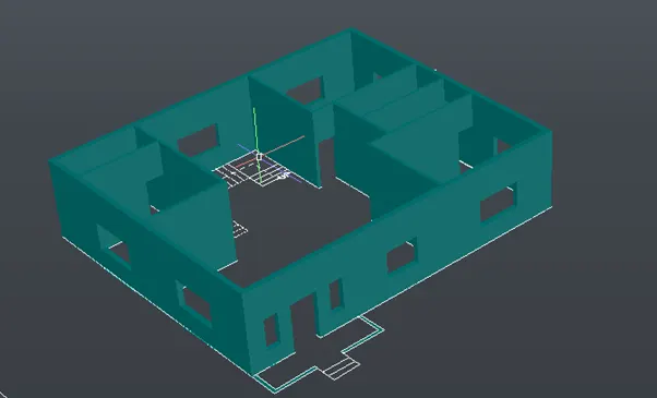
- Now, create the floor for ground floor by drawing a rectangle and then create a region and extrude it downwards at depth of 600mm.
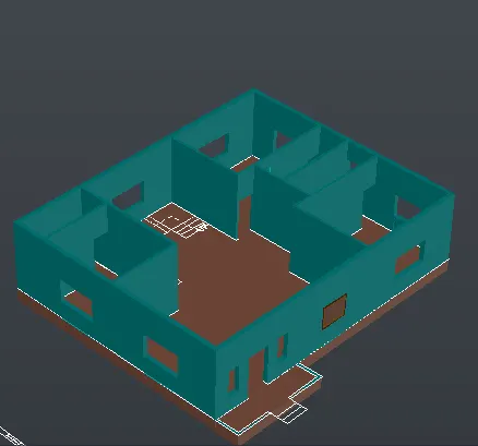
- Now, create the windowsand doors.
- For that go to elevation and copy the entire elevation beside it.
- Then in the copied elevation retain the doors and windows.
- Then change the layer to window frame and create a boundary region for the window frame.
- Then subtract the inner portion of the window.
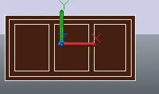
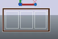
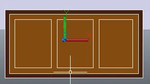
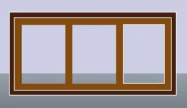
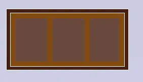
- Hence, window is created. Similarly, create the other windows.
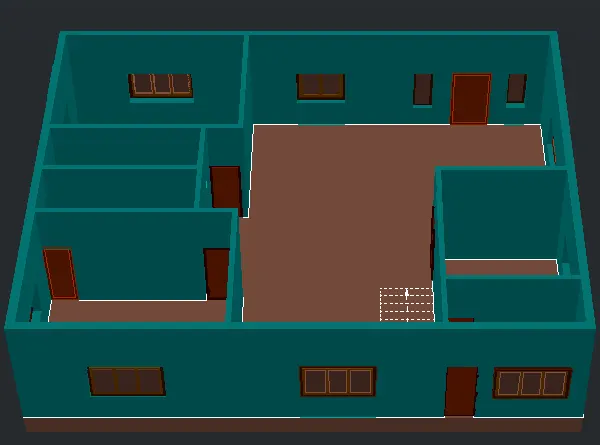
- Hence, windows and doors of the gound floor has been created.
- Similarly, windows and doors of the first floor is also created which given below:
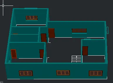
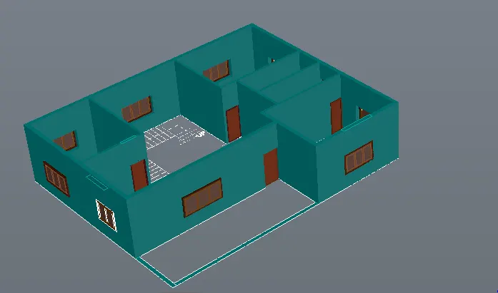
- Now, we have to develop the staircases.
- This can be created from the plan of the steps.
- So, for this, first choose the boundary command and create a region of each and every step and then extrude it as per the height of the riser, i.e 150, 300 etc.
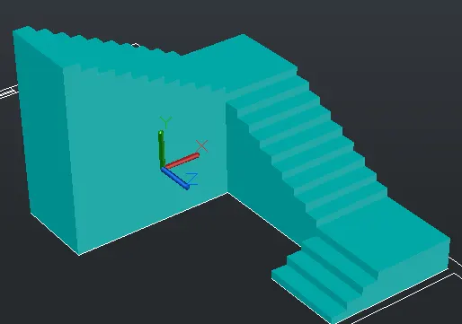
- Now, this staircase is then moved to 3D building created.
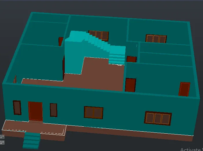
- Now, we have to create the floor for the first floor i.e the roof for the ground floor.
- For this go to the plan and choose the 3D floor layer and create a rectangle as per the inner dimension of the wall.
- Then cut the portion where there is staircase.
- Then the remaining portion is converted to region and is extruded.
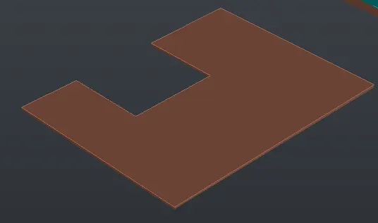
- This is then placed over the ground floor developed.
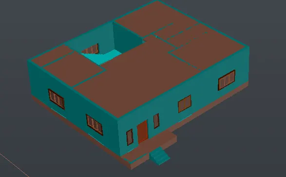
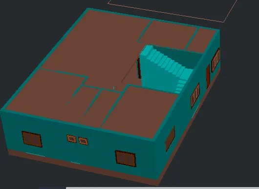
- Now, place the first floor above this.
- Now, place the roof above the first floor.
- This is done in the same way as the one created for ground floor from the plan.
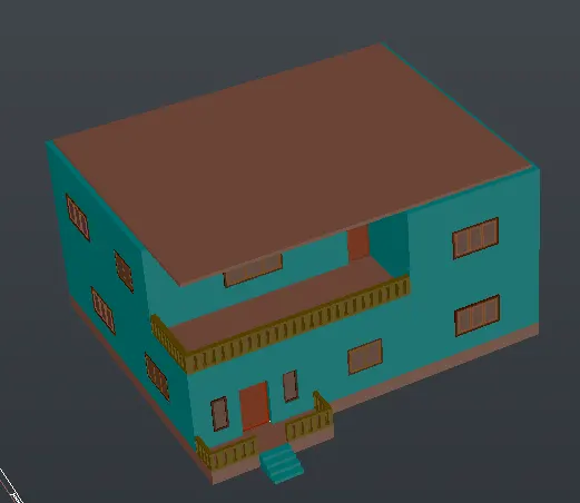
- The next we have to create the parapet above the roof.
- This is also created from the plan.
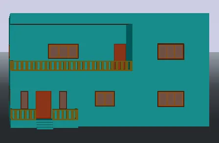
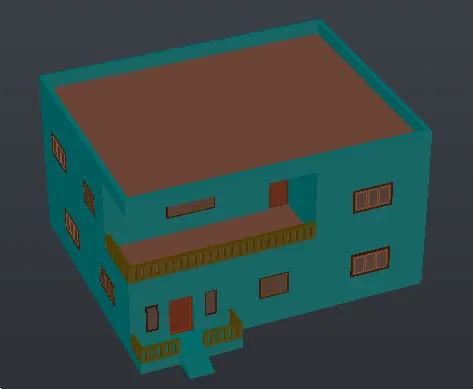
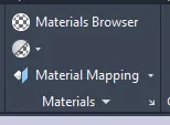
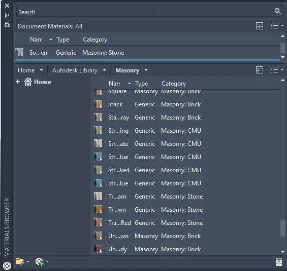
- The next step is to apply materials. This is done through material browser in the visualise panel of the ribbon.
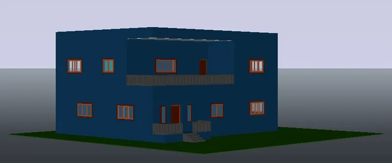
- The next step is to do the rendering, for this we have to position the camera so that better view is obtained and the view is named as camera1 and make it as realistic view.
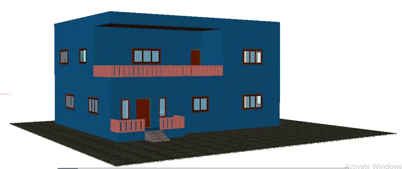
- Then, provide sky background.
- Sunlight is kept on.
- Full shadow is chosen.
- Distant light is also provided.
- Then inorder begin the rendering process we have first set the environment and exposue settings.
- Finally, we have to set the render preset.
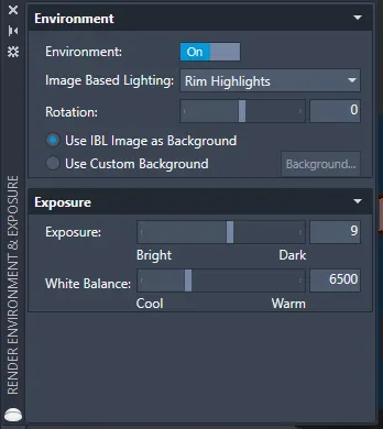
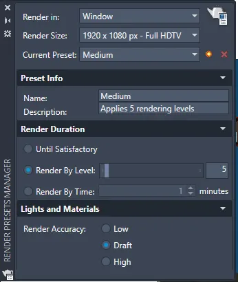
- After this, rendering process begins.
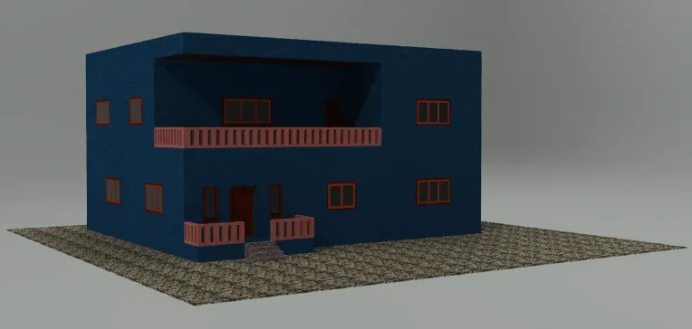
- The rendered image is obtained as given below:
Result:
The 3D rendered image of a two storey building as per the plan and elevation created is as follows:
Plan:
Elevation:
3D rendered model: