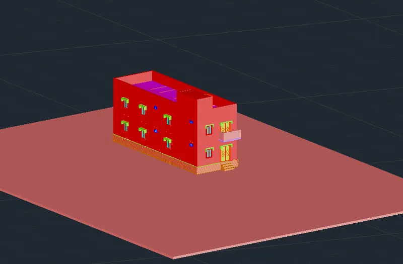
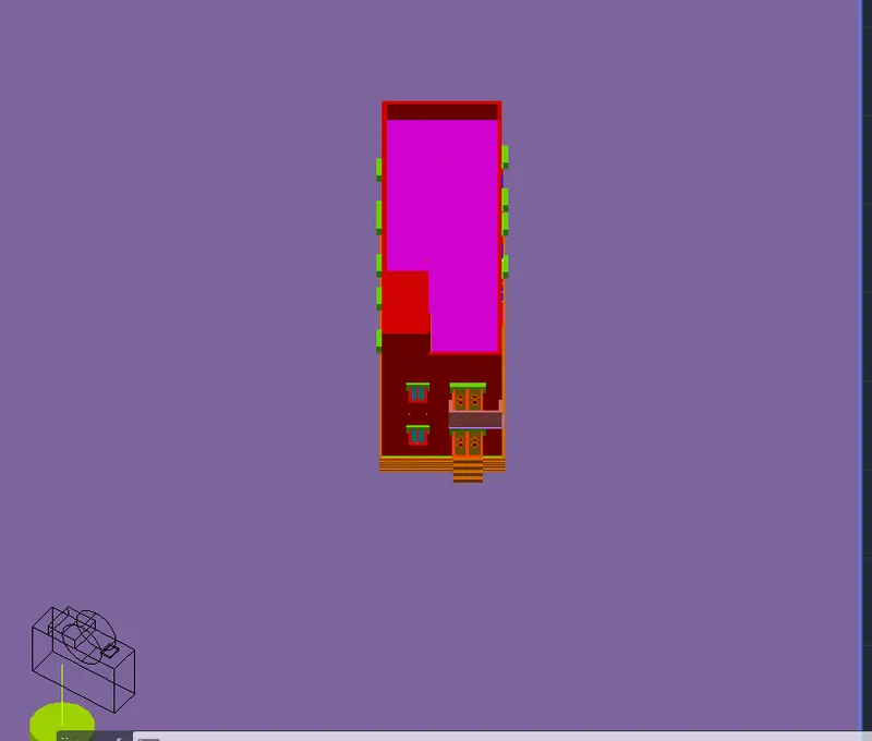
Project 2_Creating a 3D rendered model for a Residential Building in AutoCad
CREATING A 3D RENDERED MODEL FOR A RESIDENTIAL BUILDING IN AUTOCAD
AIM-
TO DRAFT A 3D VIEW OF BUILDING USING AUTOCAD
INTRODUCTION -
The main objective of this project is to understand AutoCAD 3D.
AutoCAD is three-dimensional CAD software that is used commercially across the world. Developed by Autodesk in the year 1982. AutoCAD is also available as a mobile and web app, which is marketed as AutoCAD 360. AutoCAD offers an exclusive range of commands and functions both for 3D and 2D modeling and drawing with an amazing set of tools. 3D is all about the third Z coordinate. While working in 2D, the user only cares for the X and Y axis, and most of the time, coordinates are not used. Whereas, while working with 3D, the user uses all the coordinates, which can even make their work quite easier.
Today, technology has made it possible to link our imagination a bit closer to the reality, and it can be done by 3D modeling, printing, rendering and more. A huge number of software is available in the market that offers the users to bring their imagination into reality. Some of the software is freeware, while some are priced. With every update and with continuous new discoveries, people are more attracted to the technology offering them to make and create vivid designs. The need for 3D is a necessary part of the designing world. Without it, the design almost looks like a sketch.
TOOL USED FOR MAKING 3D MODEL
EXTRUDE-Creates a 3D solid from an object that encloses an area, or a 3D surface from an object with open ends. Objects can be extruded orthogonally from the plane of the source object, in a specified direction, or along a selected path. - HOME > MODELING > EXTRUDE
SWEEP - The 2D sub-object or object is swept along an open or closed path to create a 3D surface or solid using the sweep command. The object enclosing the area is swept to create a 3D solid or surface, but an open-ended object is swept to create only a 3D surface. - HOME > MODELING > SWEEP
UNION -The Union command is used to combine the selected 2D regions or 3D solids by the addition. The selected parts are combined to form a single region, surface, or solid. But, we are required to select the parts of the same object. We can select two or more parts to combine them into a single region, solid or surface.- Click Solids > Solid Editing > UNION
SUBTRACT - Creates as a new object by subtracting one overlapping region or 3D solid from another. With SUBTRACT, you can create a 3D solid by subtracting one set of existing 3D solids from another, overlapping set - Click Solids > Solid Editing > Subtract
PROCEDURE -
STEP 1 -
- Go to START MENU, and select AutoCAD.
- The User Interface of AutoCAD is OPEN.
- Click the start Drawing tab
- The workspace of AutoCad is open,
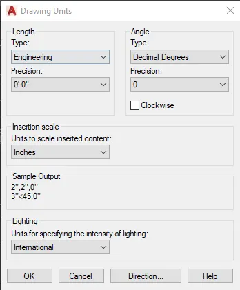
- Enter UNITS in the command box.
- Select ENGINEERING in TYPE, 0'-0" in PRECISION, and INCHES in UNITS TO SCALE INSERTED CONTENT.
- Select Angle type as DECIMAL DEGREE, and precision is 0 and direction are Anti-clockwise.
- Press OK.
STEP 2 -
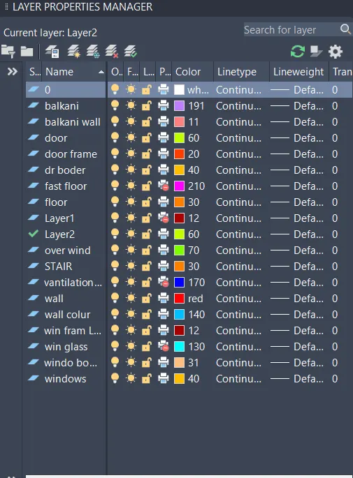
- Click on LAYER PROPERTIES tool or type LA and press ENTER
- A Layer Dialog box will open.
- Click on CREATE NEW LAYER and give a name to layer
- Here, I create a new layer with proper name
- Then, assign a differnt color for differnt layer accourding to our used.
STEP 3 -
- Select a wall layer and line tool to draw the layout of plan and use to offset tool to draw a width of wall the thickness of outer wall is taken as 9" and thickness of ineer wall is taken as 6"
- Then, select a door layer and line and arc tool to draw a door and the hinges ,sizes of door are 7'*4" and for toilet 3''7" and hinges are taken as 4"
- Then, select a window layer and line tool to draw a window and the sizes are window 3'*4'are taken as
- take a stair layer and line tool to draw the stair or tread 10 rise 11
- Use the furniture layer to place the furniture according to our use.
- bilding size 20'*60'
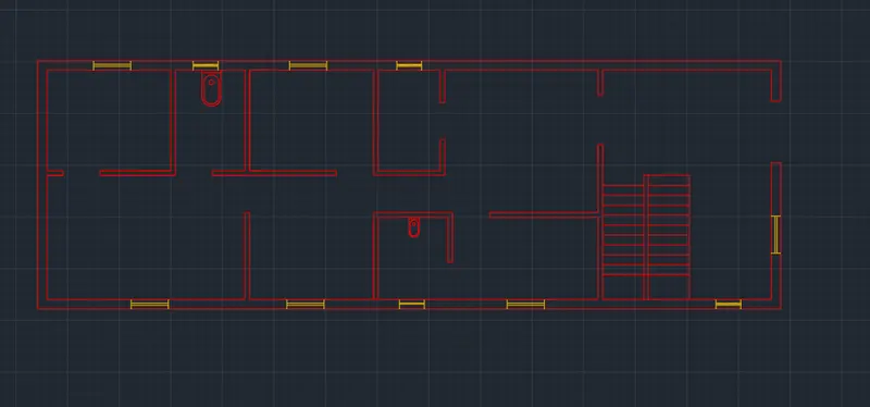
STEP 4 -
- Select a Text and dimension layer to give a name and sizes of room
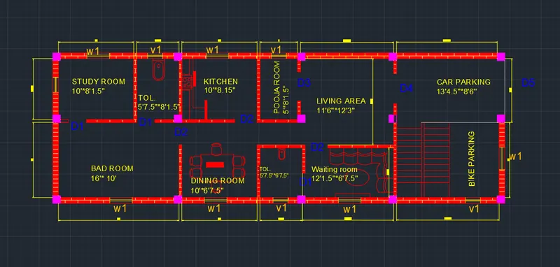
STEP 5 -
- The plan of second residential flat is similar to that. So use a mirror command to make a mirror copy of same flate and create a central door of 7'
- the plan of first, second and third floor is similar to that of ground floor
STEP 6 -
- Click on Customization at the bottom of the Model space and click on the workspace switching tab to show in the bar
- Now click on the Workspace switching and select a 3d Modeling
- Open a boundary dailog box by BO ENTER and click on pick point and click on inside every wall so the region will be created
- Select a EXTRUDE command from the modeling ribbonn and click on the last region created which is the wall and specify the heightt of wall as 10'
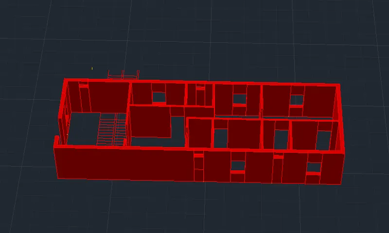
STEP 7 -
- Now we create a sill Level and lental level which is taken as 3' and 7' respectively.
- Draw a box at window and door portion and make a region by region command
- and copy the same region at the cordinate of @0,0,10'
- Select a EXTRUDE command from the modeling ribbonn and click on the last region created which is the rectangular box
- Select all the rectangle aat the ground level and specify the height of 3' as a Sill Level
- Now select a EXTRUDE command from the modeling ribbonn and click on the region created which is the rectangular box
- Select all the rectangle aat the top level and specify the height of -3' as a Lental Level
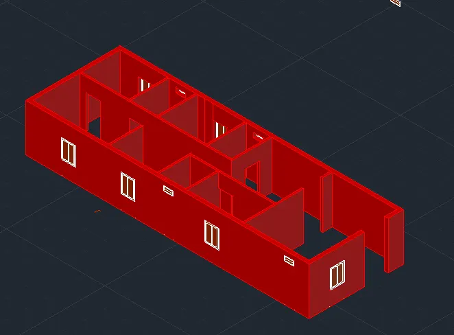
STEP 8 -
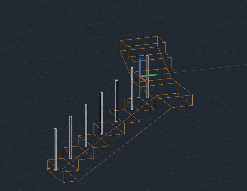
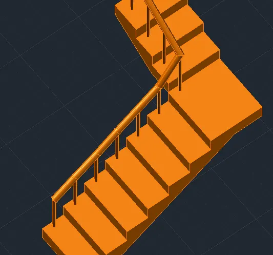
- Creating the 3d stair so first copy the plan of stair and use BOUNDARY command to make a region of every tread and landing
- Select a EXTRUDE command from the modeling ribbonn and click on the last region created which is the tread
- Specify the height of extrude 10 as a sizes of risers
- Repeat the same process and extrude second riser as 11and soo on ..
- Later cut the portionn below te slab level using substract tool.
STEP 9 -
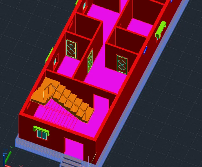
- Attach the stair to the building using move tool.
STEP 10 -
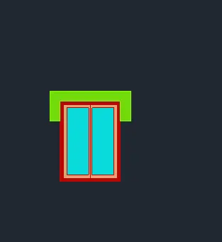
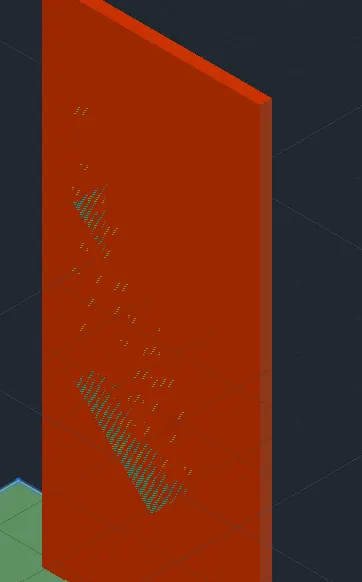
- Creating the window of size3'x4'
- Create a rectangle of 3' by4'[ use an OFFSET tool and specify the offset distance as 2'' as a mullion and create a glass of 2'2" by 2'2"
- Create a region by boundary command of mullion and glass
- Select a EXTRUDE command from the modeling ribbon and click on the last region created
- Specify the width if mullion as 4" and the width of glass as 2"
- Use a MATERIAL tool for giving the material to the window
STEP 11-
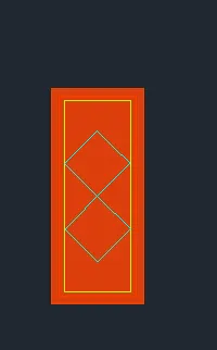
- Creating the door of size 3' by 7'
- Create a rectangle of 4 'X 7'
- Create a region by boundary command of glass
- Select a EXTRUDE command from the modeling ribbonn and click on the last region created
- Specify width of glass as 2"
- Now create handel of door by sweep command. Draw a C section using polyline and draw a circle
- Select a sweep tool and select the object press enter and select the path of sweep and press ESC
STEP 12 -
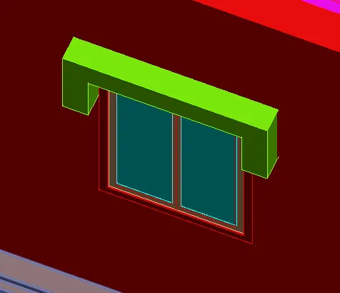
- Creating the window of size 3' x 4'
- Create a rectangle of 6'6" by 2" use an OFFSET tool and specify the offset distance as 2'' as a mullion and create a glass of 2'2" by 2'2"
- Create a region by boundary command of mullion and glass
- Select a EXTRUDE command from the modeling ribbon and click on the last region created
- Specify the width if mullion as 4" and the width of glass as 6"
- Use a MATERIAL tool for giving the material to the window
STEP 13 -
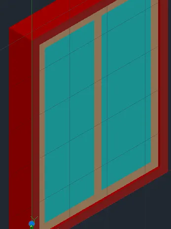
- Creating the window of size 3'x 4'
- Create a rectangle of 3'x4' use an OFFSET tool and specify the offset distance as 2'' as a mullion and create a glass of 4' by 2'
- Create a region by boundary command of mullion and glass
- Select a EXTRUDE command from the modeling ribbon and click on the last region created
- Specify the width if mullion as 4" and the width of glass as 2"
- Use a MATERIAL tool for giving the material to the window
STEP 14 -
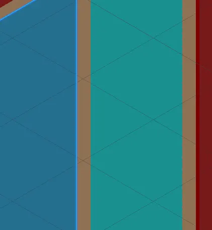
- Creating the window of size 4'x 3'
- Create a rectangle of 4'x3' use an OFFSET tool and specify the offset distance as 2'' as a mullion and create a glass
- Create a region by boundary command of mullion and glass
- Select a EXTRUDE command from the modeling ribbon and click on the last region created
- Specify the width if mullion as 4" and the width of glass as 2"
- Use a MATERIAL tool for giving the material to the window
STEP 15 -
- Creating the door of size4' by 7'
- Create a rectangle of 4 'X 7'
- Create a region by boundary command of glass
- Select a EXTRUDE command from the modeling ribbonn and click on the last region created
- Specify width as 2"
- Now create handel of door by sweep command. Draw a C section using polyline and draw a circle
- Select a sweep tool and select the object press enter and select the path of sweep and press ESC
STEP 16 -
- Creating the door of size 3' by 7'
- Create a rectangle of 3 'X 7'
- Create a region by boundary command of glass
- Select a EXTRUDE command from the modeling ribbonn and click on the last region created
- Specify width as 2"
- Now create handel of door by sweep command. Draw a C section using polyline and draw a circle
- Select a sweep tool and select the object press enter and select the path of sweep and press ESC
STEP 17 -
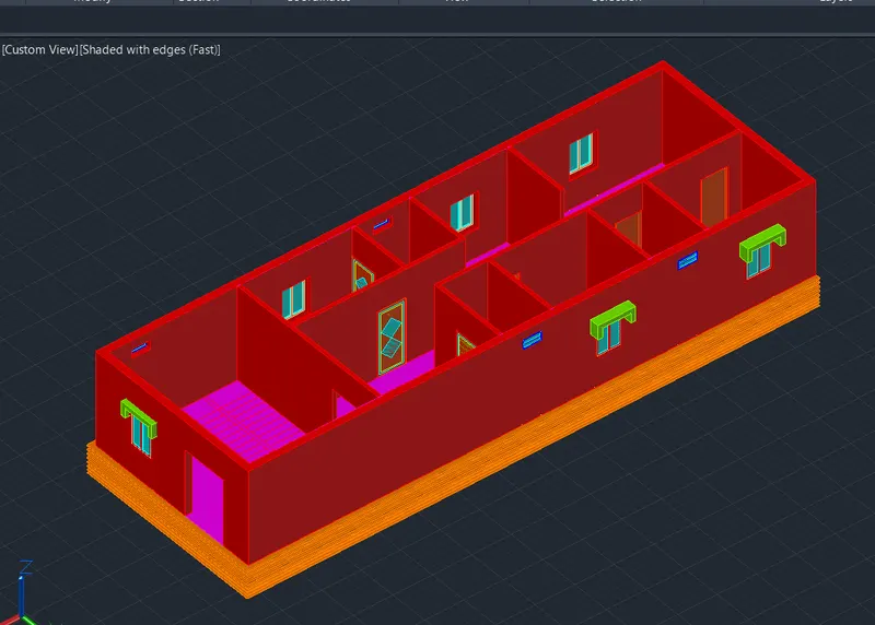
- Attach of the window and door to the building .
STEP 18 -
- To create the 3d plan of second flat use a mirror command and select the complete drawing without stair and press enter Select the base point at the end of laundry room and give th direction and press enter.
STEP 19 -
- Type MATERIAL to open the material dialog box and give the material to every wall of the room
- To Select the face of object press the right click and go to suboject selection filter and click on face now we can select the each face of wall to give the material.
STEP 20 -
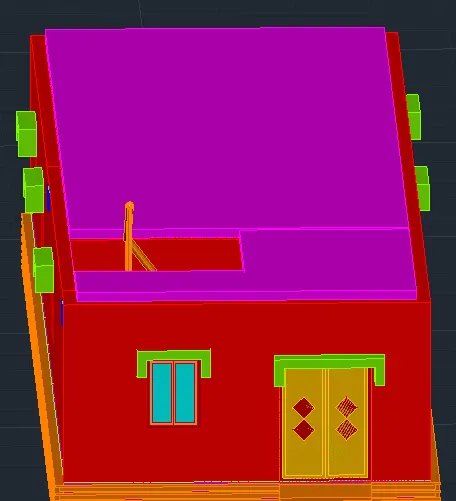
- Creating the slab
- To create the slab ,first create a rectangular box at the top of the building make the region by region command and Select the EXTRUDE command selct the rectangle and specify the height of extrude as 4"
- create one rectangle at the top of stair and OTTand use PRESSPULL Tool and press the box to create the opening
- Now our ground floor plan is ready
STEP 22-
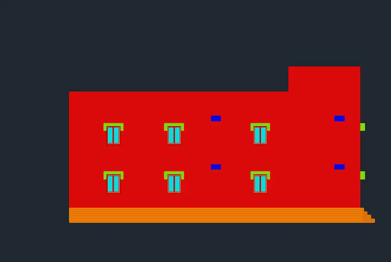
- Select the copy tool from the draw ribbon or type co and press enter for copy
- Select the entire Ground floor plan and press enter and specify th base aand and make the 3 copy and place at top of each floor
STEP 24 -
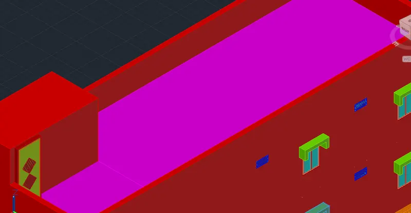
- Creating the terrace wall draw a one rectangle at top of building and give the offset of 9" as the width of wall and select the boundary command for making the region
- Select the EXTRUDE command and select the last region created and specify the
STEP 26 -
- GO to the visualize and render box
- and select the size of render image and quality of render and select the background and environment
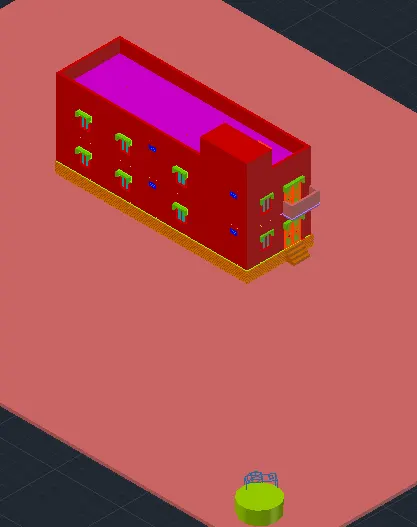
- now click on render in window or type RR to start the rendering.
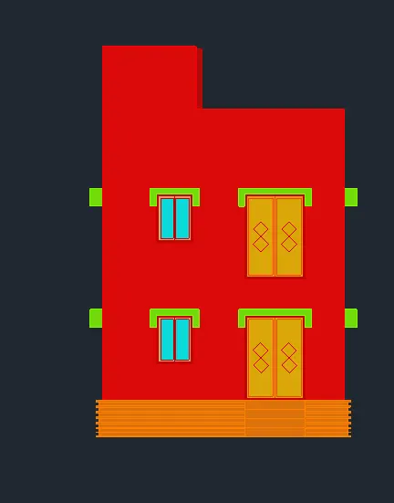
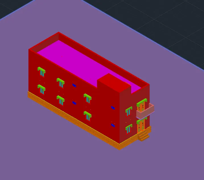
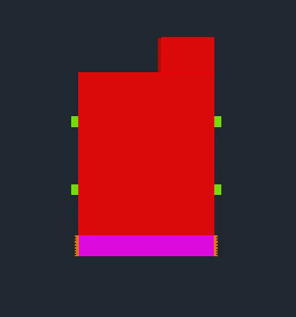
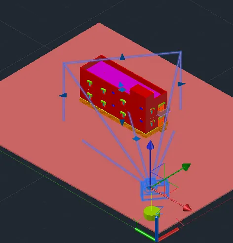
RESULT -
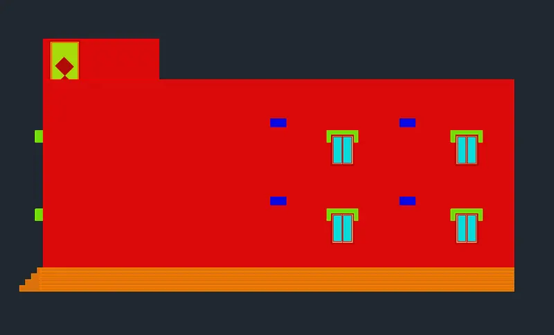
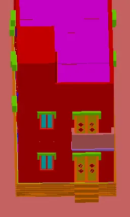
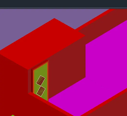
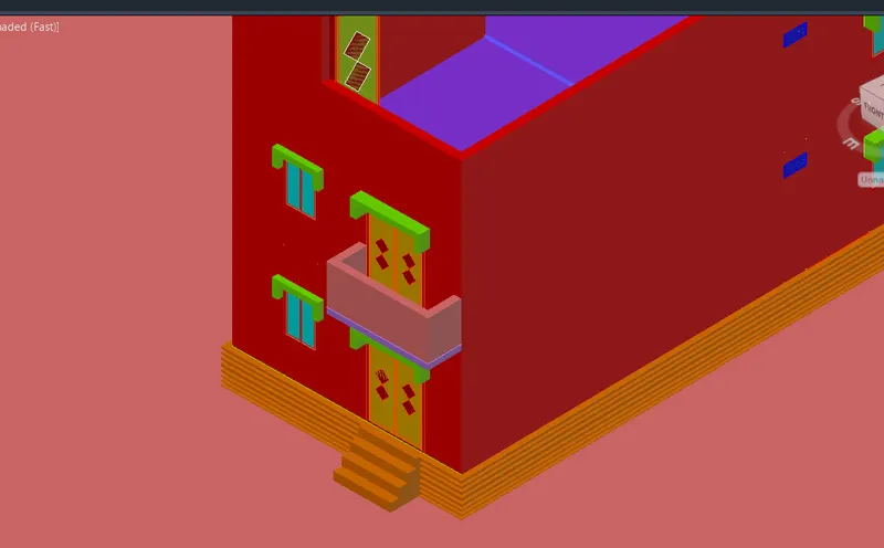
final