Project 2_Creating a 3D rendered model for a Residential Building in AutoCad
AIM : To create a 3D rendered model for a residential building in AutoCad
INTRODUCTION : North East facing residental building is created in isometric view and various isometric views of structural elements are created using following tools
3D tools
- SOLID EDIT
- REGION
- BOUNDARY
- EXTRUDE
- SWEEP
- 3DORBIT
- PRESSPULL
- UNION
- SLICE
- ROTATE 3D
- RENDERING
- MATERIAL BROWSER
- CAMERA
- LIGHT
PROCEDURE :
- Open autocad application
- Type Qnew and open new drawing
- Set units according to drawing
- Switch ON 3D modeling in work space switching
- Switch on 2D object snap and 3D object snap modes
- Ortho mode is ON
- Set units to decimal
- Set units in dimensions to decimal
2D plan drawing
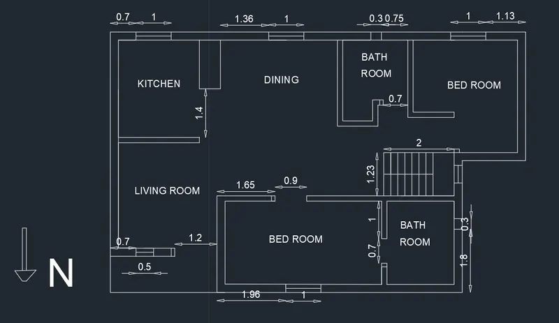
- Plan of a residential building is shown below
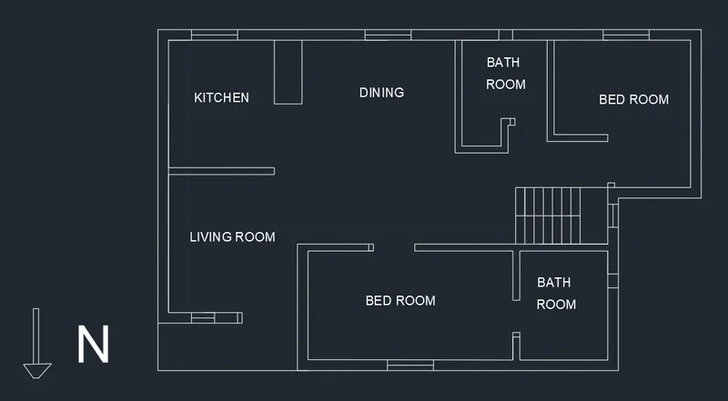
- To create above plan first draw a rectangle of size 11.81 x 7.41m
- Now take offset distance of 0.23m and draw another rectangle
- Draw living room of size 2.8 x 3m with door opening 1.2m
- In front of living room draw a rectangle of size 3 x 1m
- Beside living room draw a bedroom of size 4.45 x 2.36m with interior wall thickness as 0.15m and door opening of 0.9m
- Draw bathroom of size 1.9 x 2.36m with door opening of 0.7m
- Draw staircase of size 2 x 1.23m with thread size 0.615m and rise 0.2m
- Draw another bedroom of size 3.97 x 3.2m with interior wall thickness of 0.15m and door opening of 0.9m
- Beside bedroom draw a bathroom of size 1.85 x 2.3m with door opening of 0.7m
- Draw dinning area of size 3.32 x 2.45m
- Draw kitchen of size 2.3 x 2.7m
- Dimenions of rooms, doors, windows, staircase, bathroom ventilators are shown below
- ROOMS DIMENSIONS
- ROOMS DIMENSIONS
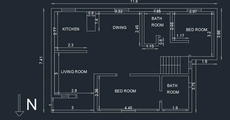
- DOORS, WINDOWS, BATHROOM VENTILATORS, STAIRCASE DIMENIONS ALONG WITH THE DISTANCES TAKEN FROM
- DOORS, WINDOWS, BATHROOM VENTILATORS, STAIRCASE DIMENIONS ALONG WITH THE DISTANCES TAKEN FROM
- Create boundary region on the interior and exterior walls
- Using extrude tool, raise the walls upto 3.5m height except the areas of doors, windows, bathroom ventilator
- Create boundary region on the areas of door, windows, bathroom ventilator
- Using extrude tool, raise the walls at door, windows regions to height of 1.5m and bathroom ventilator region to height of 2.5m
- Draw a rectangle at the top of doors, windows, bathroom ventilator regions connecting two walls
- Create a region in these rectangles and using extrude tool pulldown the regions upto 1m height (doors and windows region) and 0.5m height (bathroom ventilator region).
- Create layers as given below
- Walls
- Floor
- Roof
- Plinth
- Ground
- Bedroom Door
- Main Door
- Window
- Bathroom Ventilator
- Exhaust fan
- Parapet wall
- Draw doors, windows and bathroom ventilators separately
- For drawing a main door
- Draw a rectangle of size 1.2 x 2.5m
- Draw another rectangle with offset distance 0.1m
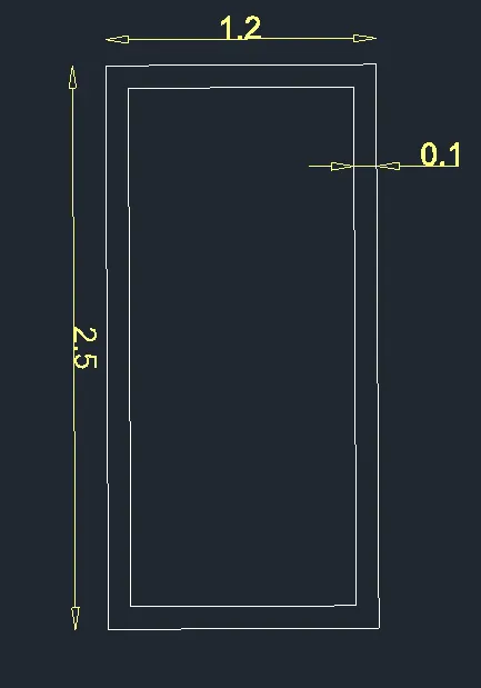
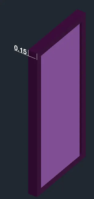
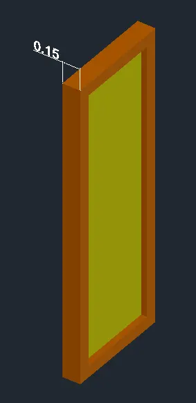
- Using extrude tool, make a solid element of door frame with thickness 0.15m and door with thickness 0.05m
- Door is moved back to 0.05m
- For drawing bedroom door
- Draw a rectangle of size 0.9 x 2.5m
- Draw another rectangle with offset distance 0.1m
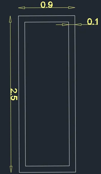
- Using extrude tool, make a solid element of door frame with thickness 0.15m and door with thickness 0.05m
- Door is moved back to 0.05m
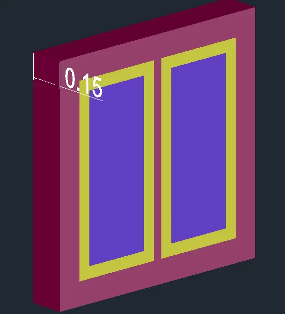
- For drawing a living room window
- Draw a rectangle of size 0.5 x 1m
- Draw another rectangle with offset distance 0.1m
- Divide the previous rectangle and draw two rectangles with offset distance 0.01m
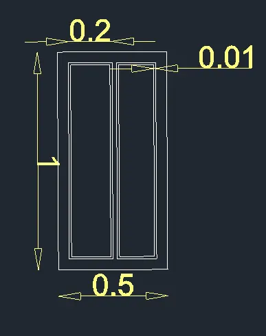
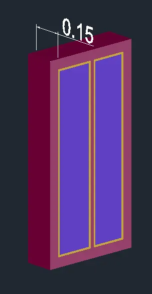
- Using extrude tool, make a solid element of window frame with thickness 0.15m, window sash with thickness 0.05m and window glass with thickness 0.01m
- For drawing a bed room window
- Draw a rectangle of size 1 x 1m
- Draw another rectangle with offset distance 0.1m
- Divide the previous rectangle and draw two rectangles with offset distance 0.5m
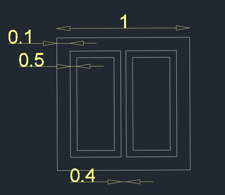
- Using extrude tool, make a solid element of window frame with thickness 0.15m, window sash with thickness 0.05m and window glass with thickness 0.01m
- For drawing a bathroom door
- Draw a rectangle of size 0.7 x 2.5m
- Draw another rectangle with offset distance 0.1m
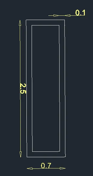
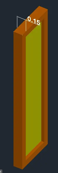
- Using extrude tool, make a solid element of door frame with thickness 0.15m and door with thickness 0.05m
- Door is moved back to 0.05m
- For drawing a bathroom ventilator
- Draw a rectangle of size 0.3 x 0.5m
- Draw a circle of radius 0.13m
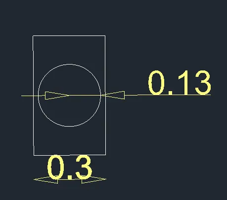
- Using extrude tool, make a solid element of thickness 0.15m and move the circle ie exhaust fan 0.5m towards back
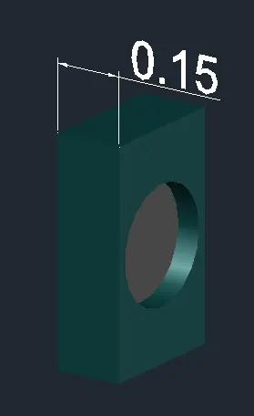
- Create staircase as given in plan
- To draw a staircase
- Draw a rectangle of size 1.23 x 2 m and divide into 2 parts
- Draw a rectangle for landing of size 1.23 x 0.6m
- Remaining area is divided into 7 parts with offset 0.2m (steps)
- Regions are made in each element and using extrude tool steps and landing are raised to height of 0.25m
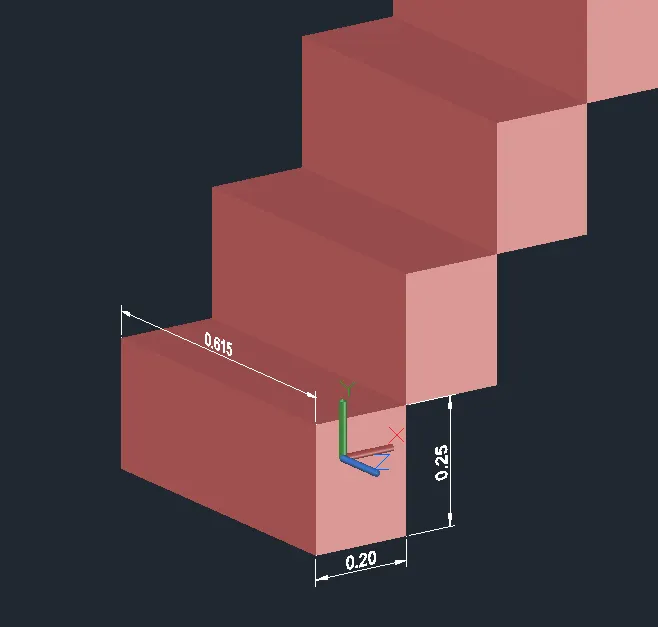
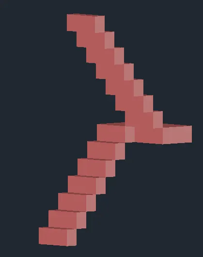
- Select union and selects objects as steps
- Place all the doors, windows, staircase and bathroom ventilator according to the plan
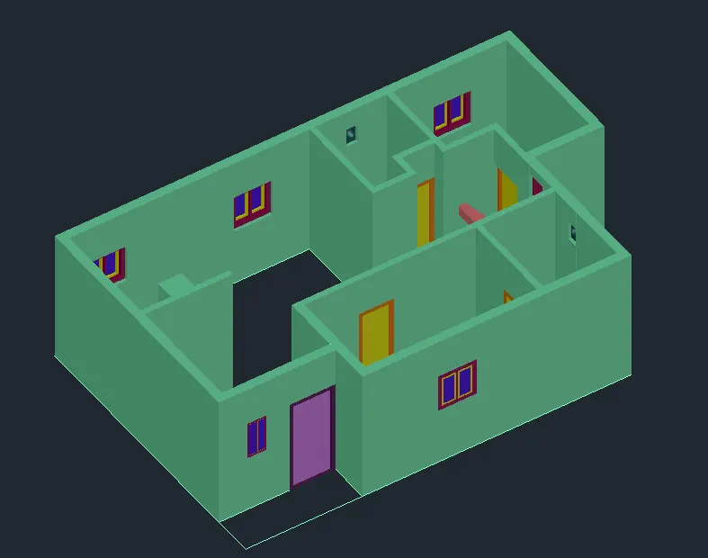
- Now create a floor at the bottom of thickness 0.1m
- Create plinth beam below with thickness 0.8m
- Create a slab at the top with thickness 0.12m (exclude the area of staircase)
- Draw walls around the opening of the staircase with wall thickness 0.15m, height 3.125m and opening of 1.53m
- Draw a door at the opening of size 1.23 width, height 3m, door frame thickness 0.15m and door thickness 0.05m
- Draw a parapet wall at the top with thickness 0.23m and height 1m
- Draw a rectangle (18 x 13m) around the residential building
- Create region of the rectangle indicating as ground level and using presspull make a thickness of 0.5m
- Assigning materials :
- Assign materials to each solid element as given below
- Wall and slab - Concrete
- Floor - Wood
- Plinth - Generic
- Ground - Generic
- Door frame - Wood
- Door - Wood
- Window sash - Plastic
- Window frame - Wood
- Window glass - Glass
- Parapet wall - Brick
- Staircase - Stone
- Kitchen element - Stone
- Bathroom Ventilator - Plastic and Exhaust fan - Metal
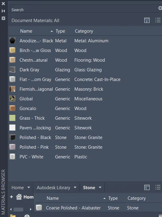
- Copy the residential building and remove slab, terrace, plinth, ground in copied building for taking pictures inside the building
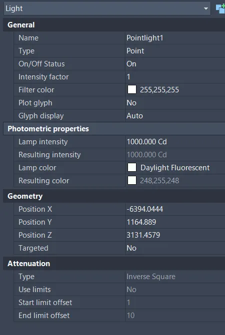
- Draw a cylinder and click on create light in visualize tab
- Place point light
- Light properties are shown below
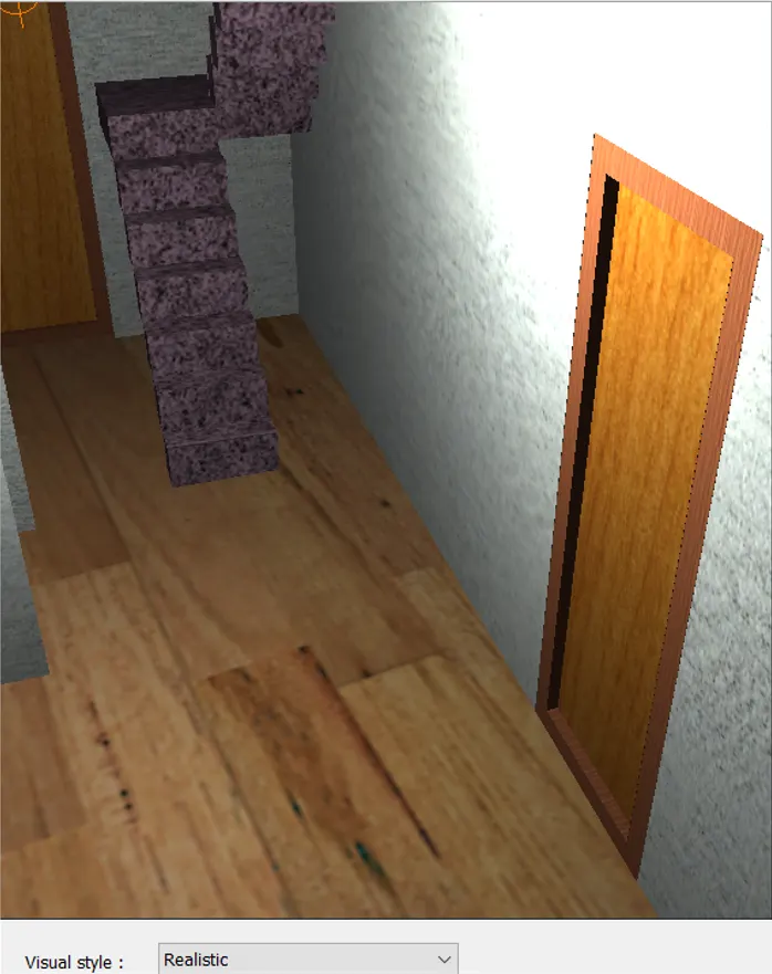
- Place a camera on the edge of wall and click the images
- Go to material browser in visualize tab and click on global (miscellaneous)
- Go to edit global and insert an image
- Now click on a wall near dining area and assign global to it
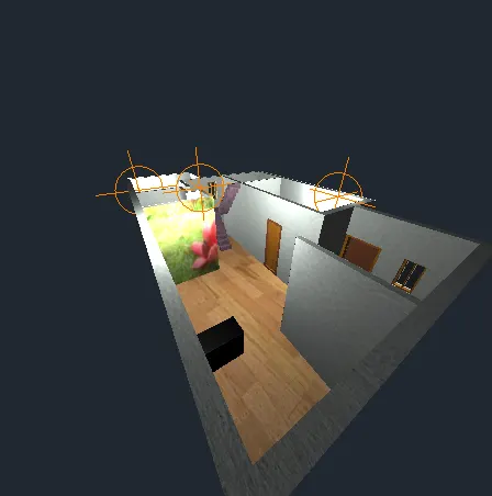
- Now to visualize tab and click on render environment and exposure in render tab
- Switch on the environment and select image based lighting : Dry lake bed
- Now click on render to size (800 x 600 px) for rendering process and save the image
RESULTS :
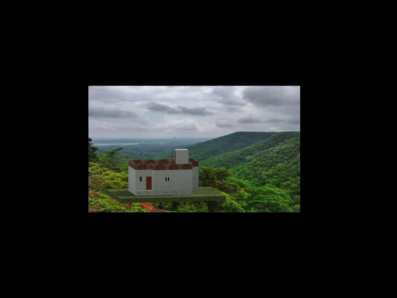
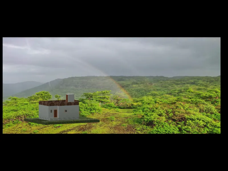
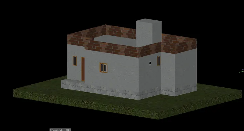
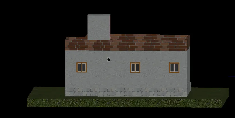
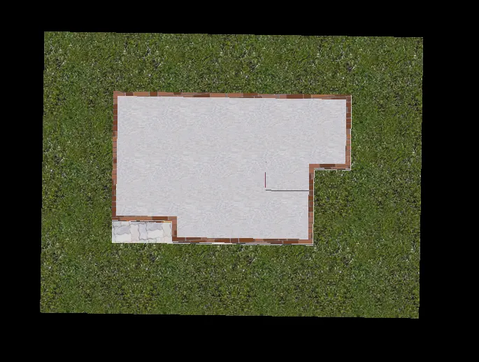
3D North east facing residential building is created with different enviroment exposures
FRONT ELEVATION
BACK ELEVATION
TOP VIEW
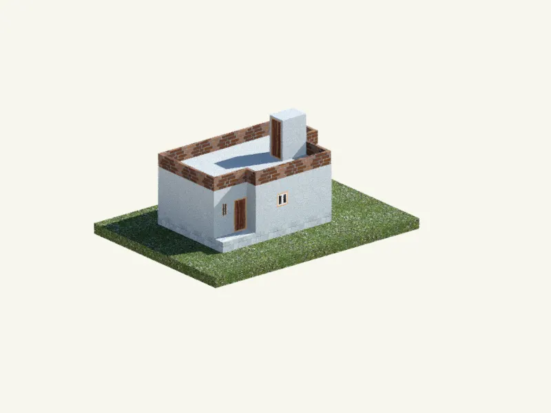
IMAGES AFTER RENDERING
Dry lake bed (Environment base lighting) and IBL Image as background
Grid light (Environment base lighting)
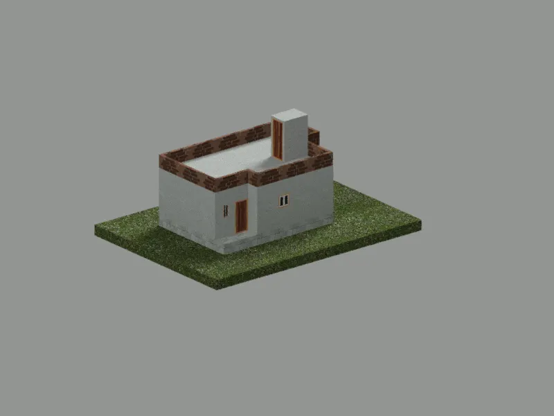
With various custom backgrounds