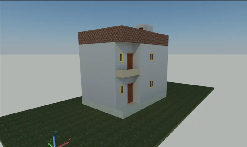
Project 2_Creating a 3D rendered model for a Residential Building in AutoCad
AIM : To create a 3D rendered model for a residential building in AutoCad
INTRODUCTION : North East facing residental building is created in isometric view and various isometric views of structural elements are created using following tools
3D tools
- SOLID EDIT
- REGION
- BOUNDARY
- EXTRUDE
- SWEEP
- 3DORBIT
- PRESSPULL
- UNION
- SLICE
- ROTATE 3D
- RENDERING
- MATERIAL BROWSER
- CAMERA
- LIGHT
PROCEDURE :
- Open autocad application
- Type Qnew and open new drawing
- Set units according to drawing
- Switch ON 3D modeling in work space switching
- Switch on 2D object snap and 3D object snap modes
- Ortho mode is ON
- Set units to decimal
- Set units in dimensions to decimal
2D plan drawing
- Plan of a residential building is shown below
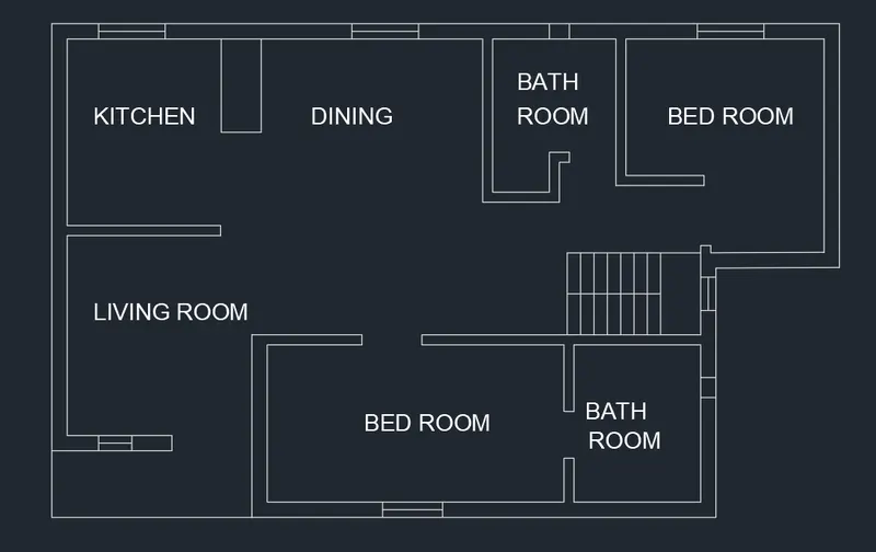
- To create above plan first draw a rectangle of size 11.81 x 7.41m
- Now take offset distance of 0.23m and draw another rectangle
- Draw living room of size 2.8 x 3m with door opening 1.2m
- In front of living room draw a rectangle of size 3 x 1m
- Beside living room draw a bedroom of size 4.45 x 2.36m with interior wall thickness as 0.15m and door opening of 0.9m
- Draw bathroom of size 1.9 x 2.36m with door opening of 0.7m
- Draw staircase of size 2 x 1.23m with thread size 0.615m and rise 0.2m
- Draw another bedroom of size 3.97 x 3.2m with interior wall thickness of 0.15m and door opening of 0.9m
- Beside bedroom draw a bathroom of size 1.85 x 2.3m with door opening of 0.7m
- Draw dinning area of size 3.32 x 2.45m
- Draw kitchen of size 2.3 x 2.7m
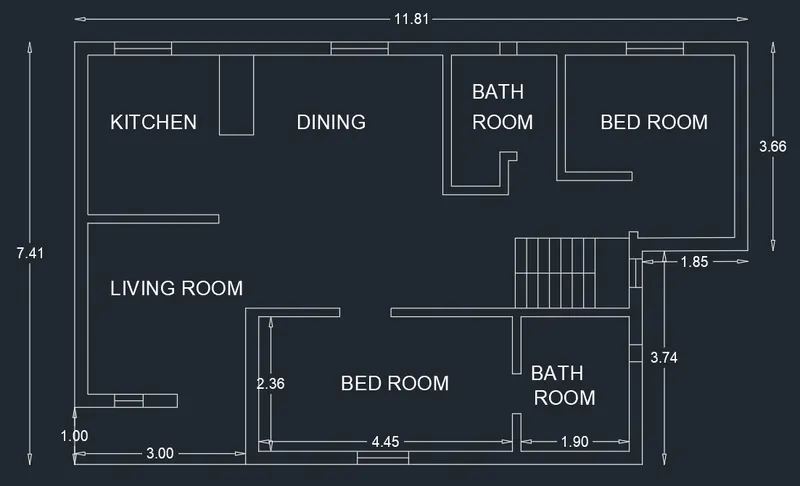
- Dimenions of rooms, doors, windows, staircase, bathroom ventilators are shown below
- ROOMS DIMENSIONS
- ROOMS DIMENSIONS
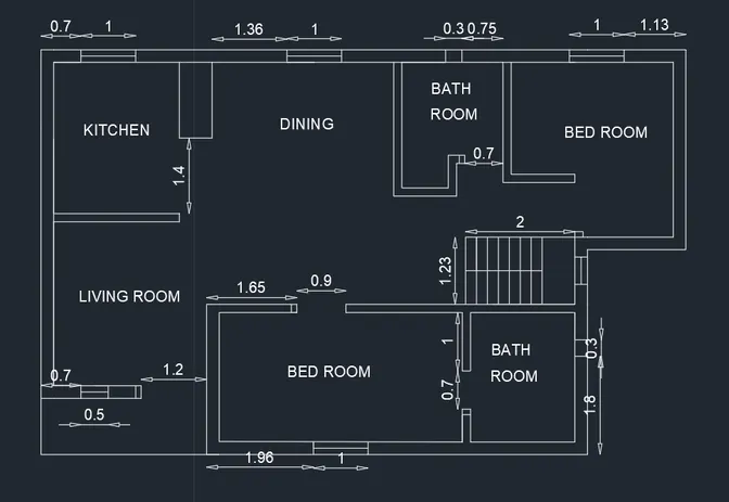
- DOORS, WINDOWS, BATHROOM VENTILATORS, STAIRCASE DIMENIONS ALONG WITH THE DISTANCES TAKEN FROM
- DOORS, WINDOWS, BATHROOM VENTILATORS, STAIRCASE DIMENIONS ALONG WITH THE DISTANCES TAKEN FROM
- Create boundary region on the interior and exterior walls
- Using extrude tool, raise the walls upto 3.5m height except the areas of doors, windows, bathroom ventilator
- Create boundary region on the areas of door, windows, bathroom ventilator
- Using extrude tool, raise the walls at door, windows regions to height of 1.5m and bathroom ventilator region to height of 2.5m
- Draw a rectangle at the top of doors, windows, bathroom ventilator regions connecting two walls
- Create a region in these rectangles and using extrude tool pulldown the regions upto 1m height (doors and windows region) and 0.5m height (bathroom ventilator region).
- Create layers as given below
- Walls
- Floor
- Roof
- Plinth
- Ground
- Bedroom Door
- Main Door
- Window
- Bathroom Ventilator
- Exhaust fan
- Parapet wall
- Draw doors, windows and bathroom ventilators separately
- For drawing a main door
- Draw a rectangle of size 1.2 x 2.5m
- Draw another rectangle with offset distance 0.1m
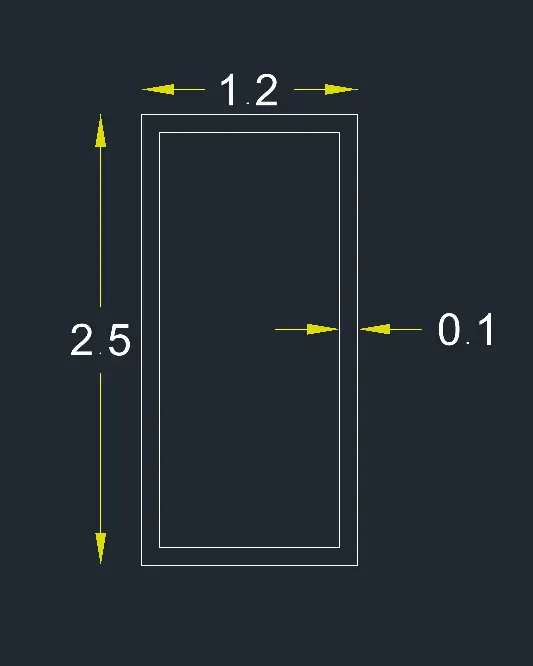
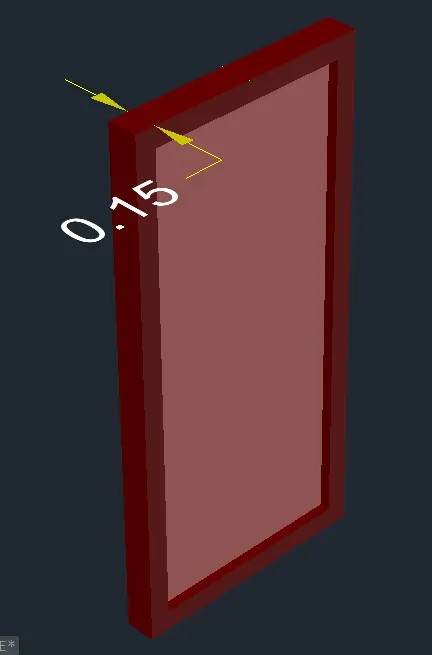
- Using extrude tool, make a solid element of door frame with thickness 0.15m and door with thickness 0.05m
- Door is moved back to 0.05m
- For drawing bedroom door
- Draw a rectangle of size 0.9 x 2.5m
- Draw another rectangle with offset distance 0.1m
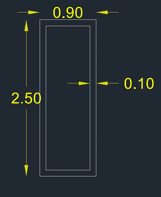
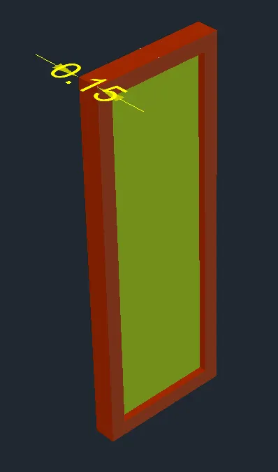
- Using extrude tool, make a solid element of door frame with thickness 0.15m and door with thickness 0.05m
- Door is moved back to 0.05m
- For drawing a living room window
- Draw a rectangle of size 0.5 x 1m
- Draw another rectangle with offset distance 0.1m
- Divide the previous rectangle and draw two rectangles with offset distance 0.01m
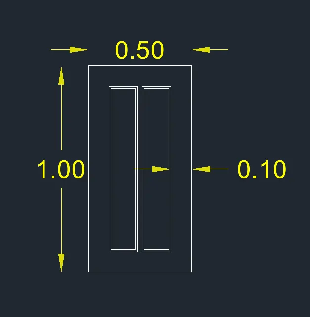
- Using extrude tool, make a solid element of window frame with thickness 0.15m, window sash with thickness 0.05m and window glass with thickness 0.01m
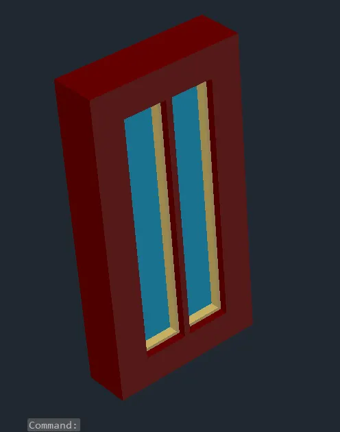
- For drawing a bed room window
- Draw a rectangle of size 1 x 1m
- Draw another rectangle with offset distance 0.1m
- Divide the previous rectangle and draw two rectangles with offset distance 0.5m
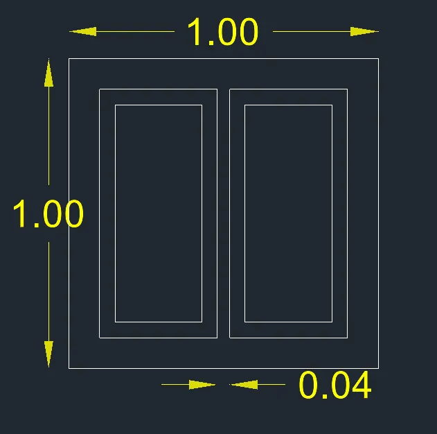
- Using extrude tool, make a solid element of window frame with thickness 0.15m, window sash with thickness 0.05m and window glass with thickness 0.01m
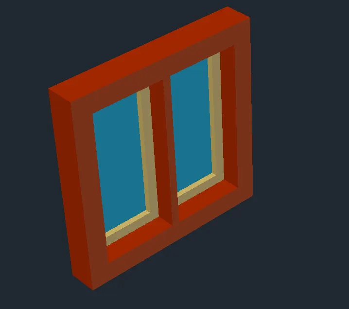
- For drawing a bathroom door
- Draw a rectangle of size 0.7 x 2.5m
- Draw another rectangle with offset distance 0.1m
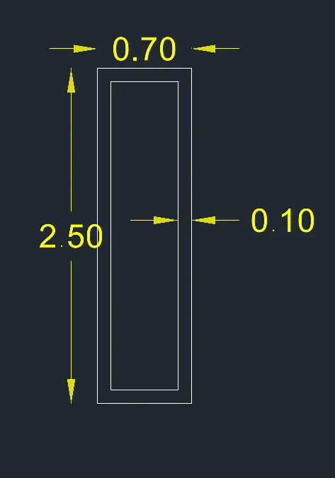
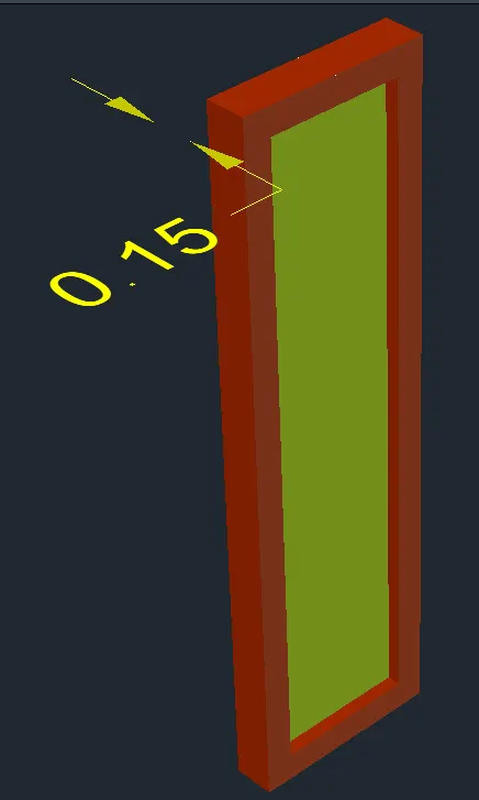
- Using extrude tool, make a solid element of door frame with thickness 0.15m and door with thickness 0.05m
- Door is moved back to 0.05m
- For drawing a bathroom ventilator
- Draw a rectangle of size 0.3 x 0.5m
- Draw a circle of radius 0.13m
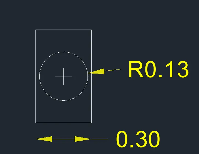
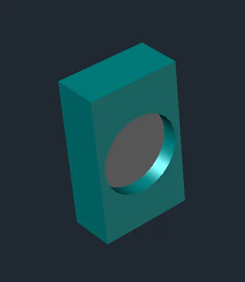
- Using extrude tool, make a solid element of thickness 0.15m and move the circle ie exhaust fan 0.5m towards back
- Create staircase as given in plan
- To draw a staircase
- Draw a rectangle of size 1.23 x 2 m and divide into 2 parts
- Draw a rectangle for landing of size 1.23 x 0.6m
- Remaining area is divided into 7 parts with offset 0.2m (steps)
- Regions are made in each element and using extrude tool steps and landing are raised to height of 0.25m
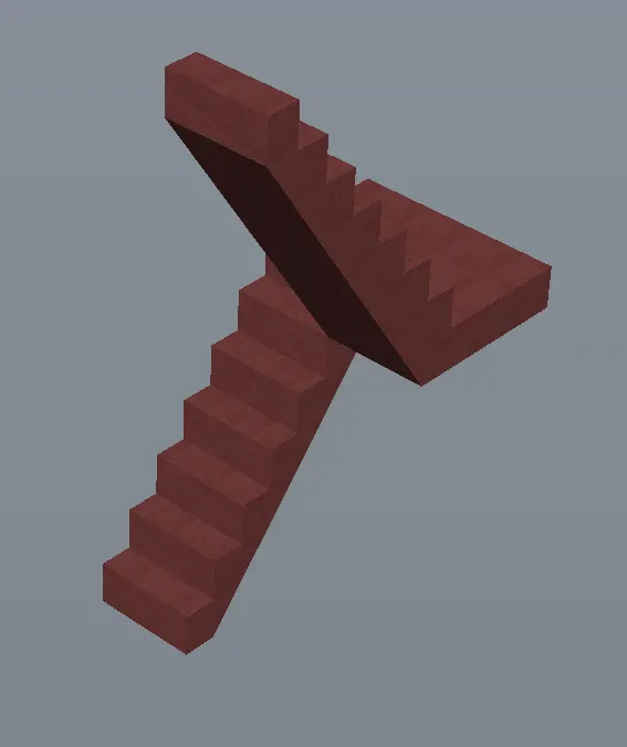
- Select union and selects objects as steps
- Place all the doors, windows, staircase and bathroom ventilator according to the plan
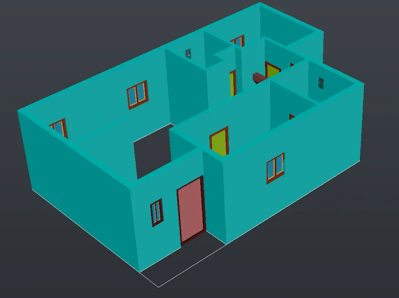
- Now create a floor at the bottom of thickness 0.1m
- Create plinth beam below with thickness 0.8m
- Create a slab at the top with thickness 0.12m (exclude the area of staircase)
- Draw walls around the opening of the staircase with wall thickness 0.15m, height 3.125m and opening of 1.53m
- Draw a door at the opening of size 1.23 width, height 3m, door frame thickness 0.15m and door thickness 0.05m
- Draw a parapet wall at the top with thickness 0.23m and height 1m
- Draw a rectangle (18 x 13m) around the residential building
- Create region of the rectangle indicating as ground level and using presspull make a thickness of 0.5m
- Assigning materials :
- Assign materials to each solid element as given below
- Wall and slab - Concrete
- Floor - Wood
- Plinth - Generic
- Ground - Generic
- Door frame - Wood
- Door - Wood
- Window sash - Plastic
- Window frame - Wood
- Window glass - Glass
- Parapet wall - Brick
- Staircase - Stone
- Kitchen element - Stone
- Bathroom Ventilator - Plastic and Exhaust fan - Metal
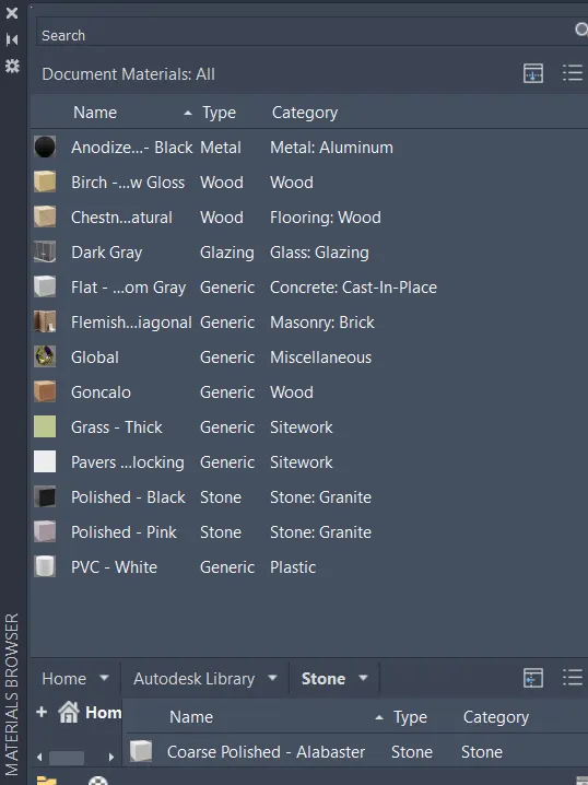
- Copy the residential building and remove slab, terrace, plinth, ground in copied building for taking pictures inside the building
- Draw a cylinder and click on create light in visualize tab
- Place point light
- Light properties are shown below
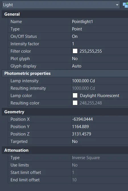
- Place a camera on the edge of wall and click the images
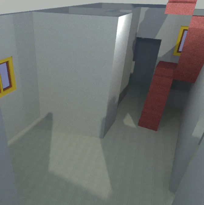
- Go to material browser in visualize tab and click on global (miscellaneous)
- Go to edit global and insert an image
- Now click on a wall near dining area and assign global to it
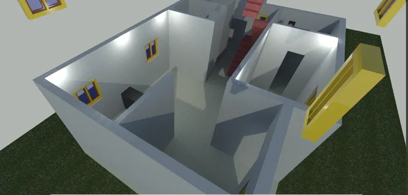
- Now to visualize tab and click on render environment and exposure in render tab
- Switch on the environment and select image based lighting : Dry lake bed
- Now click on render to size (800 x 600 px) for rendering process and save the image
RESULTS :
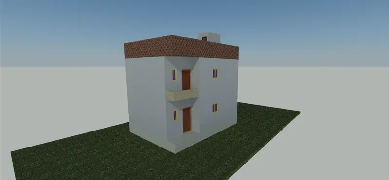
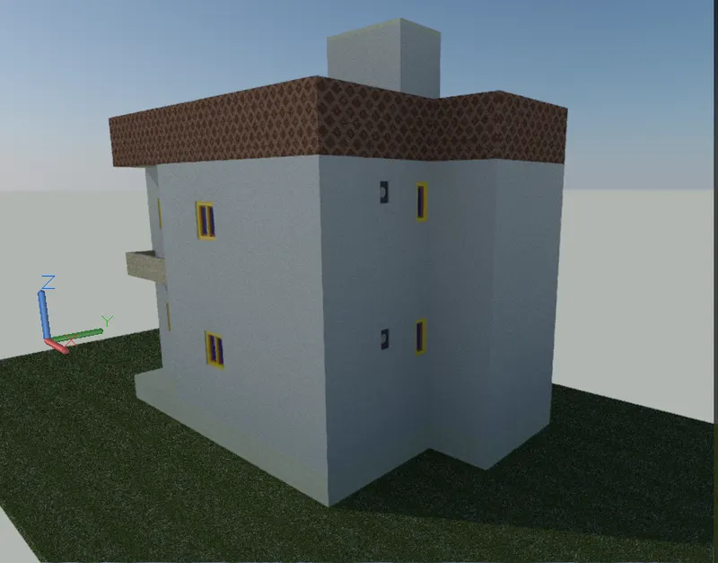
3D North east facing residential building is created with different enviroment exposures
FRONT ELEVATION
BACK ELEVATION
TOP VIEW
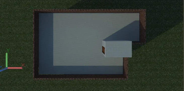
IMAGES AFTER RENDERING