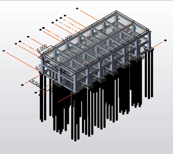
Project 2_Analyze and Design the RC office building as per IS standard code in TEKLA STRUCTURAL DESIGNER
Que :- Develop general arrangement for the RC office building. Analyze and design the building as per IS standard code in TEKLA STRUCTURAL
DESIGNER. Refer the attached plan and elevation. The building to be designed for dead, live, wind and seismic loading.
Report of each member to be generated and extract drawings for structural plans, beam reinforcement details from the software
Ans :-
Aim : To develop generral arrangement For The RC Office Building And To analyze And Design The Building For dead Load , Live , Wind And seismic Loading
Procedure :-
- A Rough Drawing Is Done To Give The Position Of Beams And Columns To The Plan
- A New Tekla Is Opened And It Saved Accordingly
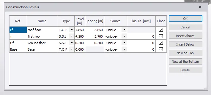
- Construction Levels Are Added In Tekla Software
- Base Level To Ground Level Is 0.5 m
- Ground Floor Levels To First Floor Level Is 3.7 m
- First Floor Level To roof Level Is 3.65 m
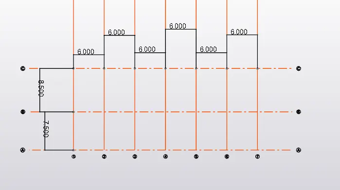
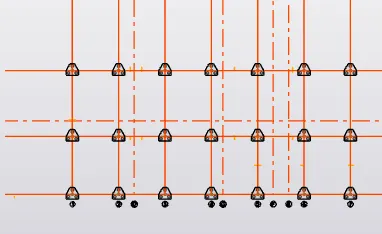
-Then The Gride Are added
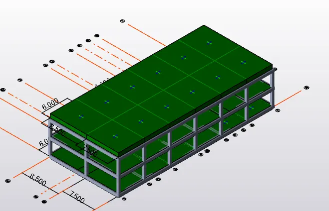
- Vertical Grids 1 To 7 each Of Distance 6m
- Horizontal grids A To B Is 7.5 m
- B To C Is 8.5m
- After This The Model Is Validated
- Now We Go To Manage Property Sets
- Column > M55 > Section > 400 X 400
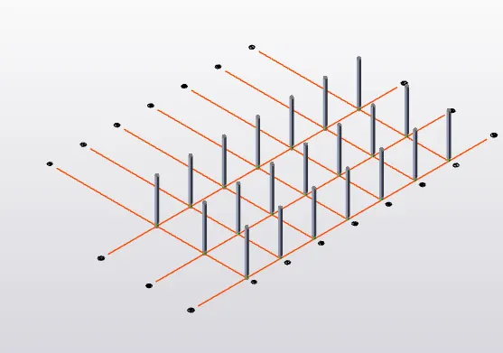
- Now We Go To Manage Property Sets
- Beam > M55 > 600 X 600
- The Beam Is Modelled According The Ground Floor Plan
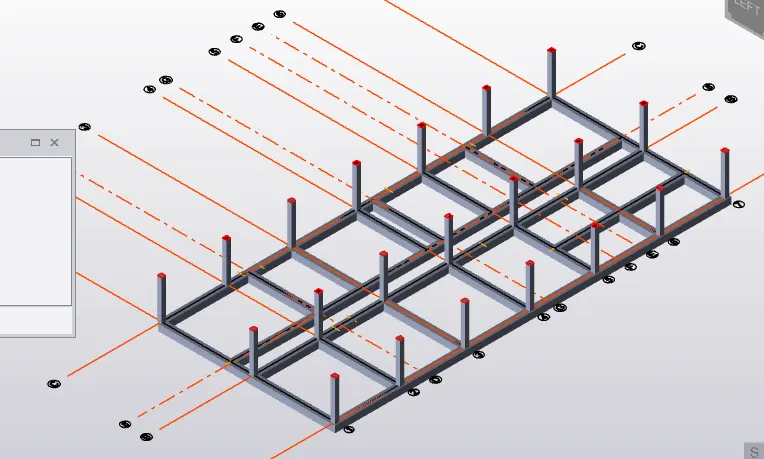 ( Ground Floor Plan )
- Same Procedure Is Followed For The First Floor As Well
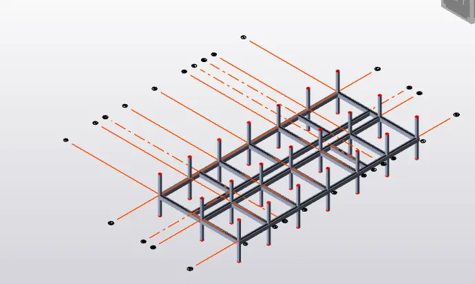 ( First Floor )
- Even For The Roof The Beams Are Added
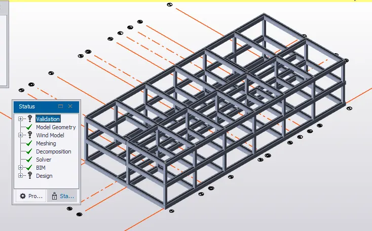
- Now The Beams Are added To The Staircase
- Now The Beams For Staircase Are Created
- First Add The Required Beams And Columns To The Substructure > Staircase

- After This We go Model Tab > slope
- The staircase Slope Are Created
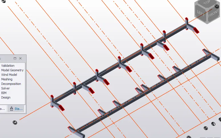
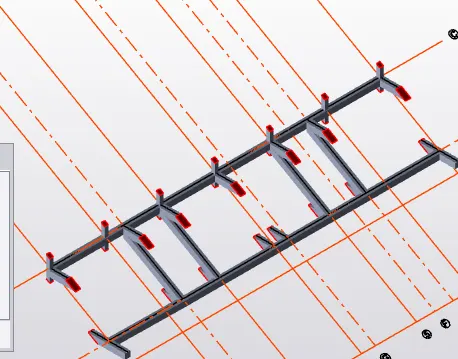
- Therefore The Staircase Beams are created
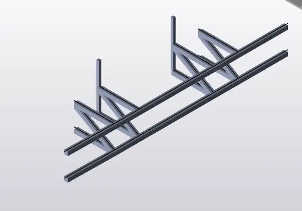
- Now Slab , Is Created
- Manage Property Sets > Slabs
- Slabs > M55 > Overall Depth > 900mm > M55
- One - Way Slabs , Two - Way Slabs
- Slabs Are Added To Added To Ground Floor , First Floor , Staircase And Roof Floor
- While Adding For The Staircase > Include In Diaphrams > Is Unselected
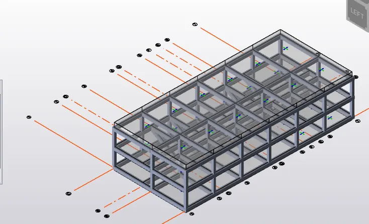
- Staircase Slab :
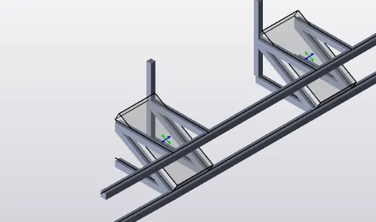
- As The structure Of The Model Is Done
- Now We have The Loadings
Manual Calculation Of Dead Loads :

Manual Calculation Of Live Loads :
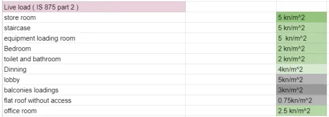
Manual Calculation Of services Loads :

- This Loads Are Now Added To The model
Dead Load :
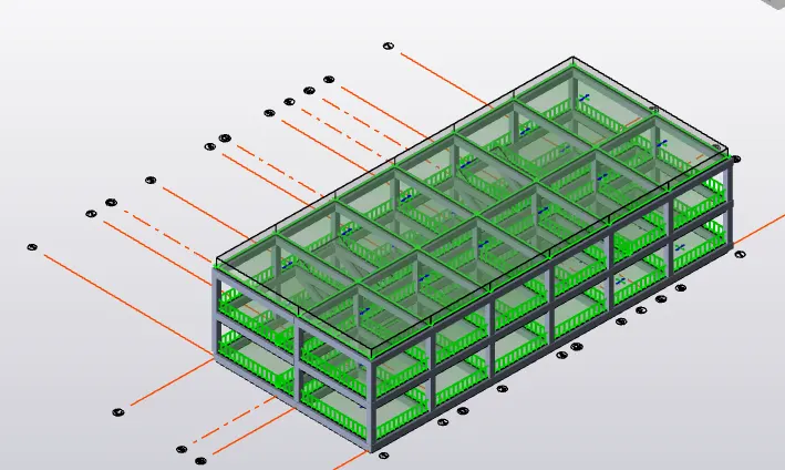
- Service Load And Live Load :
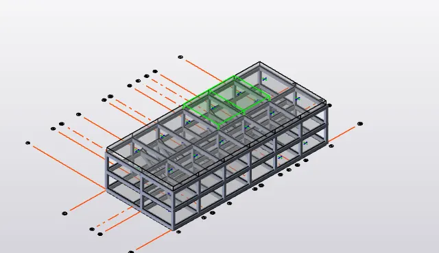
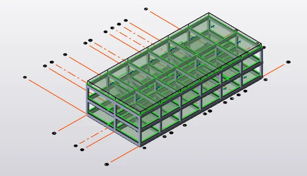
Sesmic Load Is Addded :
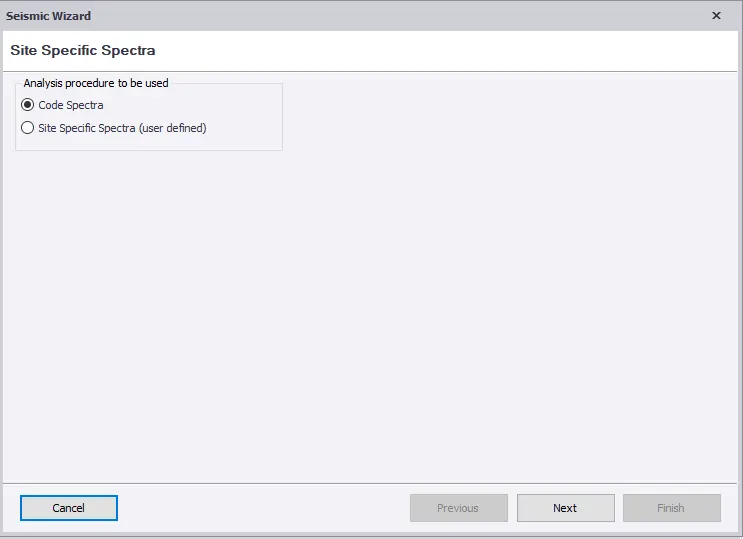
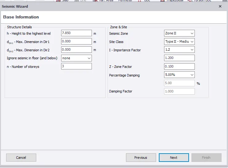
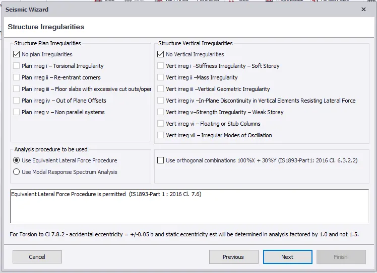
- Load > Sesmic Load > Sesmic Wizard > Code Spectra > Next
- Zone II
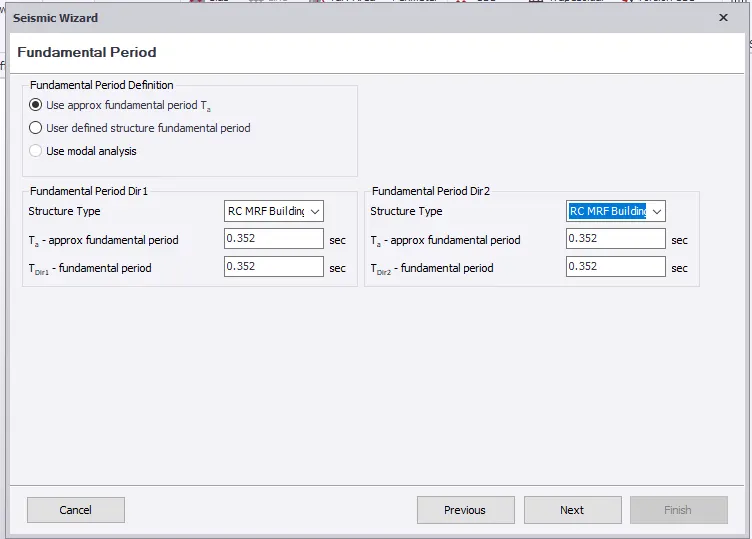
- RC MRF Building
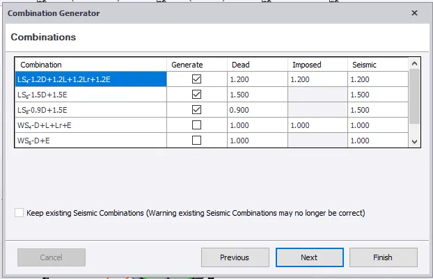
- Load Combination Are Generated
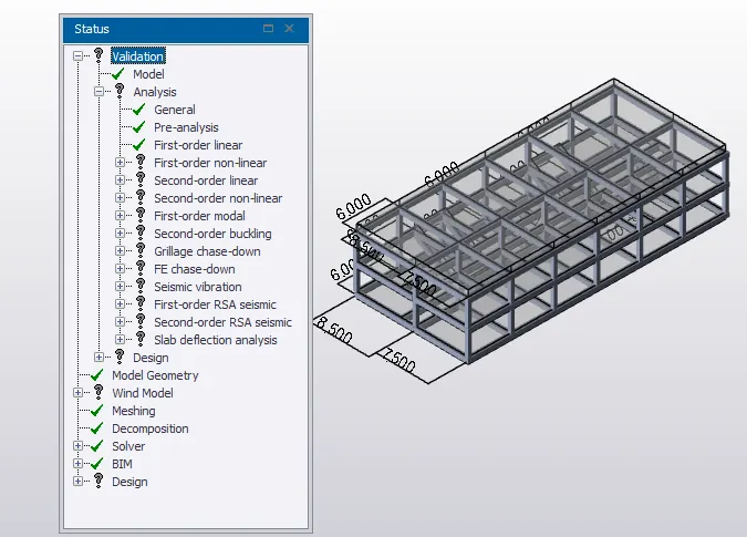
- Normal Validation Is Done
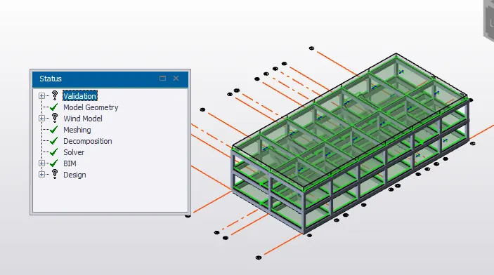
- After This Analze Is Done
- Analyze > Tab > 1st Order Analysis
- Analyze For Wind Load Is Not Done As My Building Does Not Exceed 10m Height
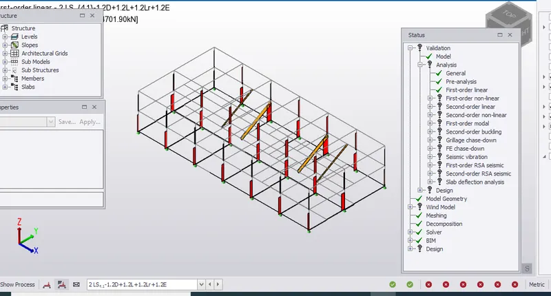
- Result View > Axial force
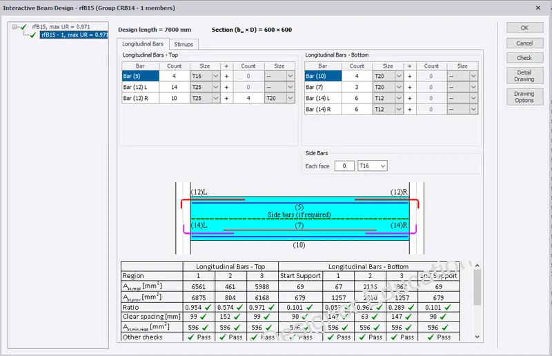
- After This Is Done The Interactive Design For Beams , Columns And Slab Are Done Beams
- Right Click On The Beams
- Interactive Design
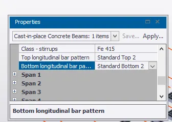
- Properties
- Top Longitudinal Bar Pattern > Standard Top 2
- Bottom Longitudinal Bar Pattern > Standard Bottom 2
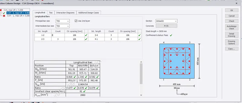
- The Same Process Is Followed For Column As Well
- Column > Right Click > Interactive Design
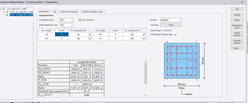
- Design Is Check Is An Errors Is Found
- Ast Is Changed Accordingly And Also The Section Size Ot The Column Is Increasedd
- Now We Go To Result View And Check This Slab Design
- Slab > Check Panel
- This Is Failed As The Ast Provided Does Not Satisfied The Ast Required
- In The Properties Sets , Have Changed The Reinforcement Details from T6 To T16 with 200mm Spacing
- Foundation
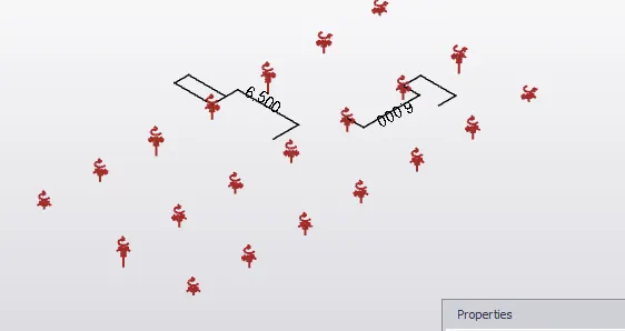
- Go To Ground Floor > Supports
- Go To Result View And Click On Reaction
- F2'' > Vertical Shear force
- Now We Go To Settings
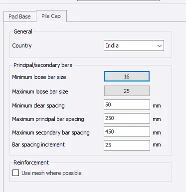
- From setting > Foundation Setting > Reinforcement Layout > Isolated Footing > Pile cap
- Pile Cap > Minimum Vbar size 16
- Minimum Clear Spacing = 50mm
- Maximum Clear spacing = 250mm
- Foundation size
- Minimum Size > 300mm
- Maximum Size > 1500mm
- General Parameters
- Maximum Nominal Aggregate = 20mm
- Tolerance For Pile Position Variation = 75mm
- Piles
- Minimum = 3
- Maximum = 5
- Home > Foundation > Cataloge
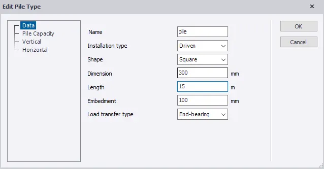
- None : Pile
- Installation Type : Driven
- Shape : Square
- Dimension = 300mm
- Length = 15m
- End = Bearing
- Bar Size = 20mm
- Spacing = 200mm
- Overall depth = 1000mm
- Pile Cap spacing = 1000mm
- Fy = 450
- Grade : M55
- Pile Cape : 3
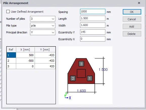
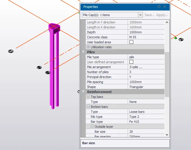
- Once This Is Done The Foundation Is Checked For Design
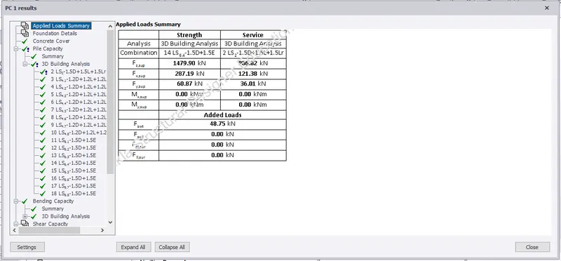
- The same Procedure Is Followed For All The Other columns
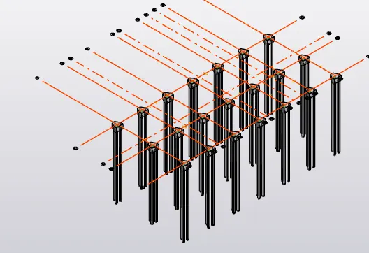
Report :
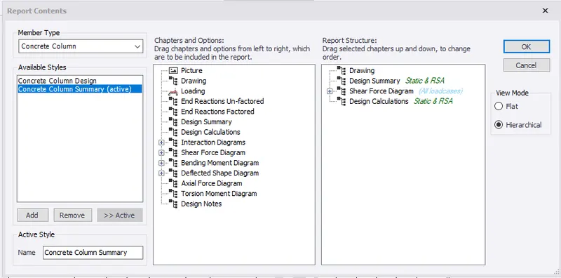
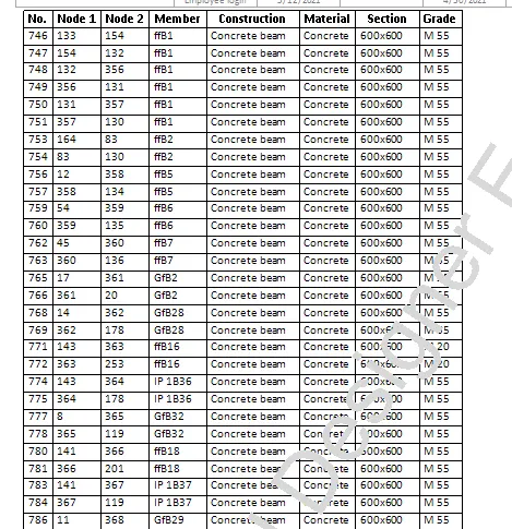
- Report > Member Report > Show Report
- Select > drawing Summary , Shear Force Diagram , Design calculation Etc
Result :-
The analyses And Design Of The Given Building Is Done