Project 2 Adaptive Cruise Control
Main Project:
AIM:
- To Develop the Adapitve Cruise Control using MATLAB Simulink.
- Model Base Development (MBD) Requierment as SLLD, Configaration parameter, Model adivser Check & Code Generation Flowing in this Project
Project Decription:
- In this Project three Diffrenyt Statdes a) Lead Vechical ,b) Drive Vechical c) Adaaptive Curues Contoral algorithm.
Lead Vechicle:
As per the Requirement document, implemented the Adaptive Cruise Control feature.
- Lead Vechical Moniter around vechical movemnt
- The Two input Signal a)Camara b) Rader Signal
- Comparing Both input speed shout be contorol speed of vechical
- Speed vechical monitering Adaptive Cruise control Algorithm
Drive Vechicle:
To regulate the "Drive Vehicle speed, as per the Requirement Document added Cameralnput. Radarinput & Acceleration Mode feedback from ACC Algorithm.
- Drive Vechical speed as per the requirment document added camara input and radwe input and Acclaration Feedback from Asaptive Curise Control(ACC)
- To detect the Lead vechicle. raderinput is converting using signal conversion block
- To avoid the algerbraic error unit delay block is used for the accleration mode feedback.
Adaptive Cruise Contorol(ACC)
Adaptive Cruise Control feature has 3 major modes of operation: OFF Mode. STANDBY Mode & ON Mode. This particular requirement has to be implemented as state machine logic in Simulink
• The input signals to the state machine system are (Signal Name Time Gap. Set Speed Set Gap, CruiseSwitch SetSwitch) Also, the output signals (Signal Name DriveVehicle Speed & LeadVehicle Detected) from requirement-2 is fed back as an input signal into this state machine block
• Additionally, the output signal (Signal Name LeadVehicle Speed) from requirement-1 is given as an input signal to this state machine
• Output from this subsystem a signal (Signal Name Acceleration Model which governs the vehicular speed of the drive vehicle which automatically adjust to speed & velocity to match the lead vehicle.
• The rest of the signal developed as per the Requirement
Simulink Model Devalopment:
1.Lead vehicle Simulink Model:
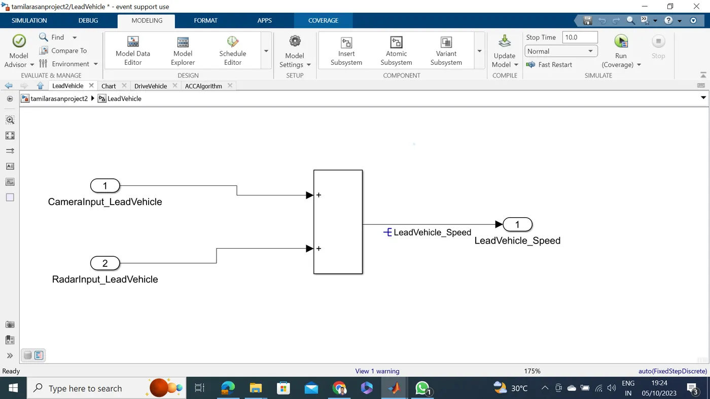
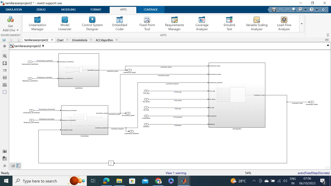
Lead Vehicle is a vehicle which is driving in the road ahead of our drive vehicle. Two input signals (Signal Name: CameraInput_LeadVehicle & RadarInput_LeadVehicle).
-
Ideally sensor fusion techniques will be deployed to process & analyze data from camera & radar. For complexity reasons, let’s not adapt to any such algorithms.
-
We can simply add both the radar & camera inputs & the corresponding output is read as Speed profile output (Signal Name: LeadVehicle_Speed).
-
Speed data of the lead vehicle is critical in implementing the Adaptive Cruise Control algorithm.
Requirement 2 – Drive Vehicle:
Drive Vehicle is the vehicle driven by the user & this is the vehicle which has ACC algorithm in it.
-
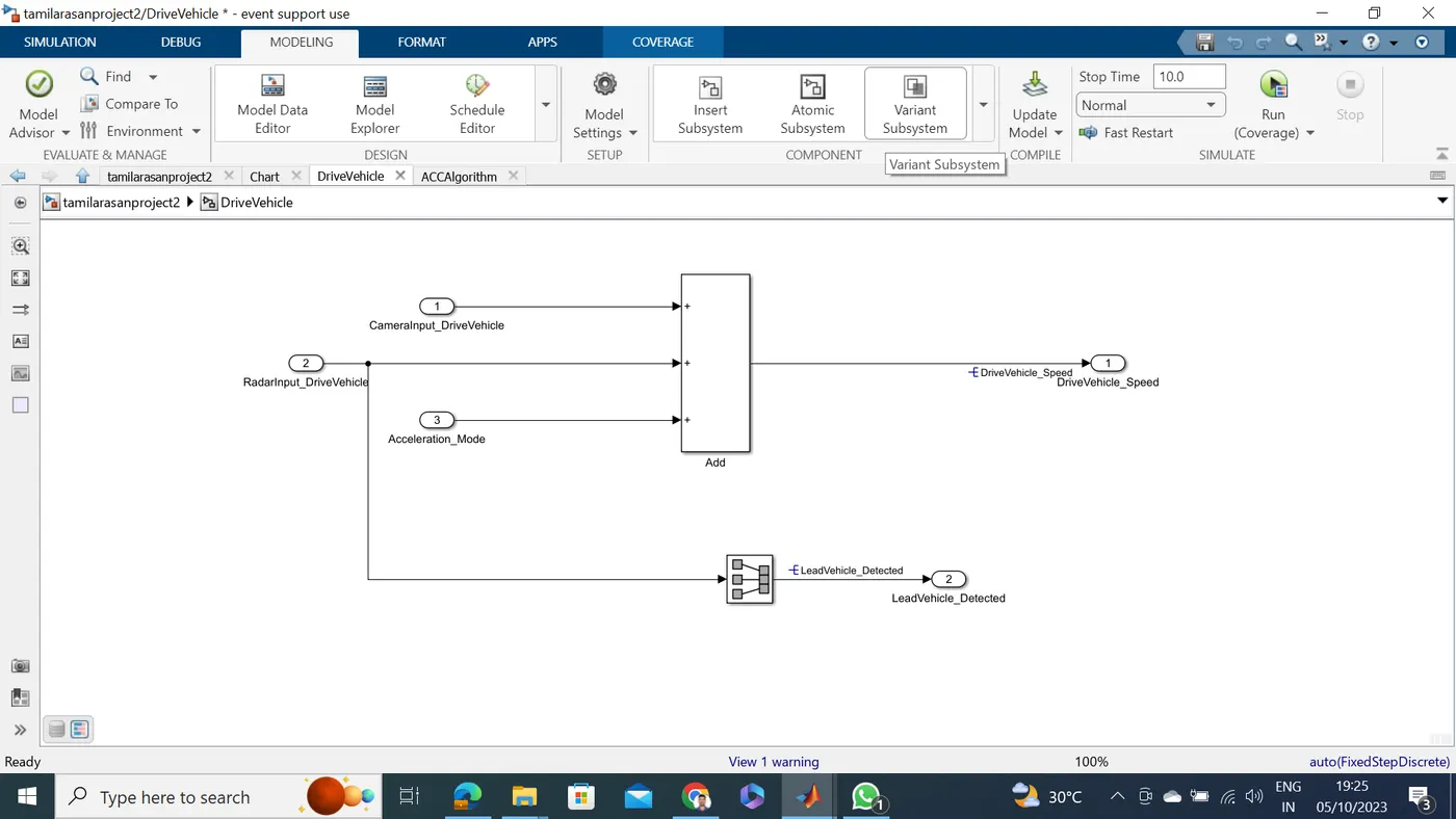
Like the Lead Vehicle, Drive Vehicle algorithm also has 2 input signals (Signal Name: CameraInput_DriveVehicle, RadarInput_DriveVehicle) & one signal coming as an Input to this subsystem (Signal Name: Acceleration_Mode) – three inputs into this requirement in total.
-
Like the above requirement, sensor fusion techniques will also be deployed here, for complexity reasons we are ignoring them.
-
Two output signals come from this subsystem (Signal Name: DriveVehicle_Speed & LeadVehicle_Detected).
-
Signal DriveVehicle_Speed is summation of three input signals mentioned above & LeadVehicle_Detected is renamed from Input Signal RadarInput_DriveVehicle by mere use of Signal Conversion block.
Requirement 3 – Adaptive Cruise Control Algorithm:
-
Adaptive Cruise Control feature has 3 major modes of operation: OFF Mode, STANDBY Mode & ON Mode. This particular requirement has to be implemented as state machine logic in Simulink.
-
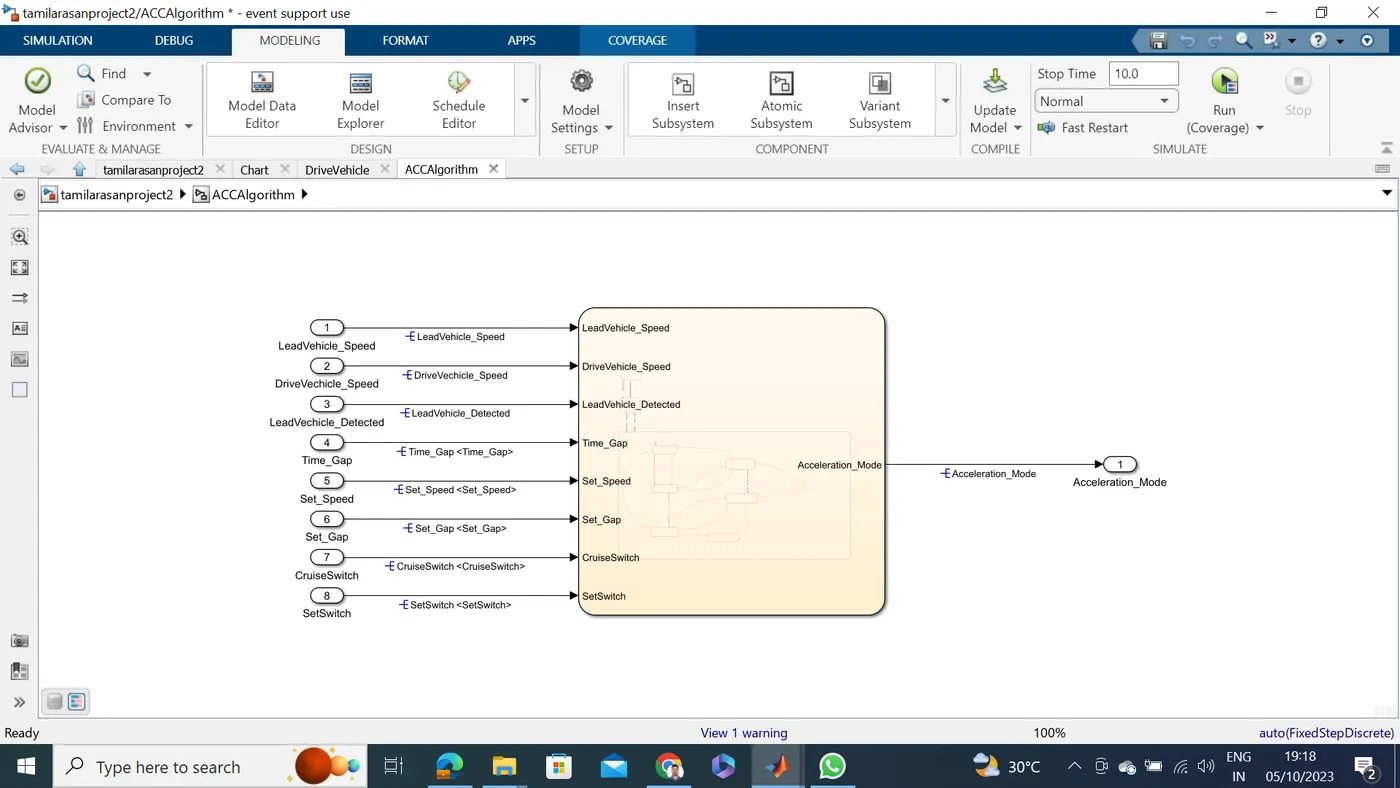
The input signals to this state machine system are (Signal Name: Time_Gap, Set_Speed, Set_Gap, CruiseSwitch, SetSwitch).
-
Also, the output signals (Signal Name: DriveVehicle_Speed & LeadVehicle_Detected) from requirement-2 is fed back as an input signal into this state machine block.
-
Additionally, output signal (Signal Name: LeadVehicle_Speed) from requirement-1 is given as an input signal to this state machine block as well.
-
Output from this subsystem is a signal (Signal Name: Acceleration_Mode) which governs the vehicular speed of the drive vehicle which automatically adjusts its speed & velocity to match the lead vehicle.
Requirement 3a – ACC OFF MODE state logic:
-
This is the default state inside state machine logic. Output signal Acceleration_Mode is at value 0 in this state.
-
This state is governed by input signal CruiseSwitch.
-
If CruiseSwitch is equal to 1, state ACC STANDBY mode will get activated. If CruiseSwitch is equal to 0, state ACC OFF mode will get activated, from either ACC ON mode or ACC STANDBY mode
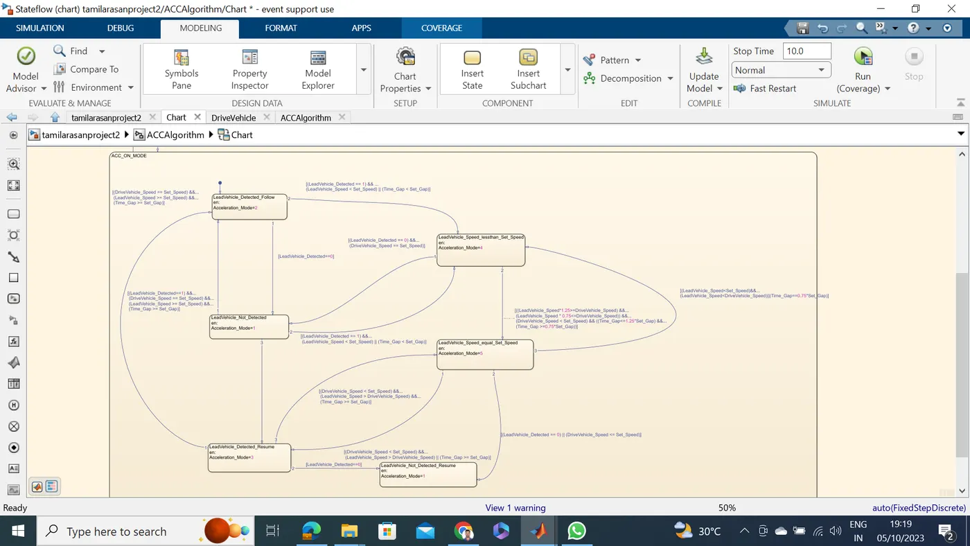
Chart:
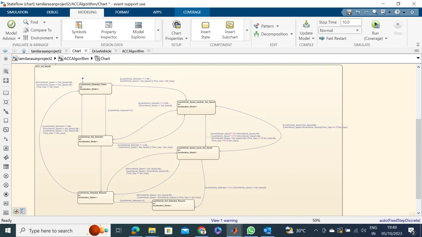
All Requierment Data Completerd Link the SLLD File.
Check Covrange and Generate Report:
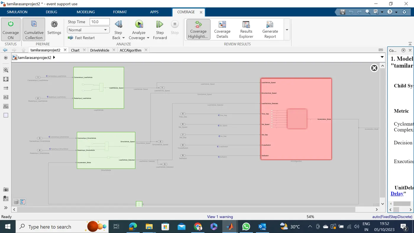
Coverage Repoart enclosed Attachment:
Developing SLDD :
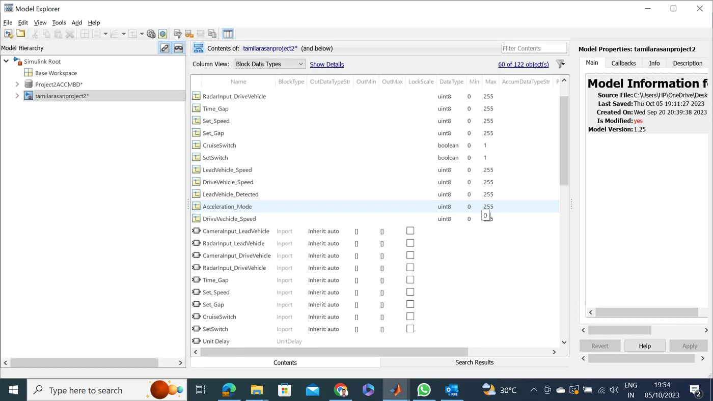
all the inputs, outputs, calibration parameters are saved in SLDD so while simulation the model takes all the values and its parameters from the Simulink Data Dictionary
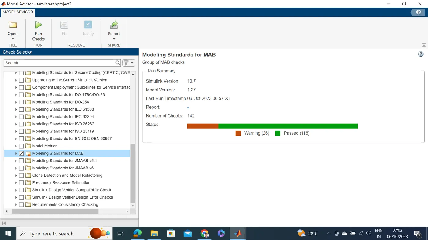
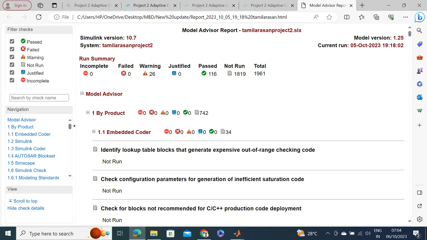
Model Advisory Report:
By running the model advisor tool, we can see commonly made modelling errors.
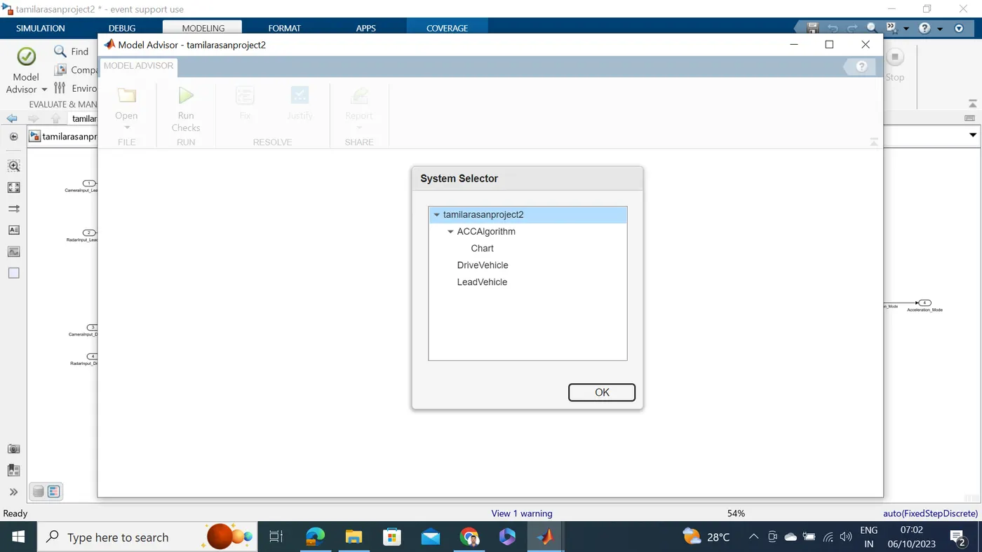
After Run Model Advisor and Select Modeling Standards for MAB
Code Genearation:
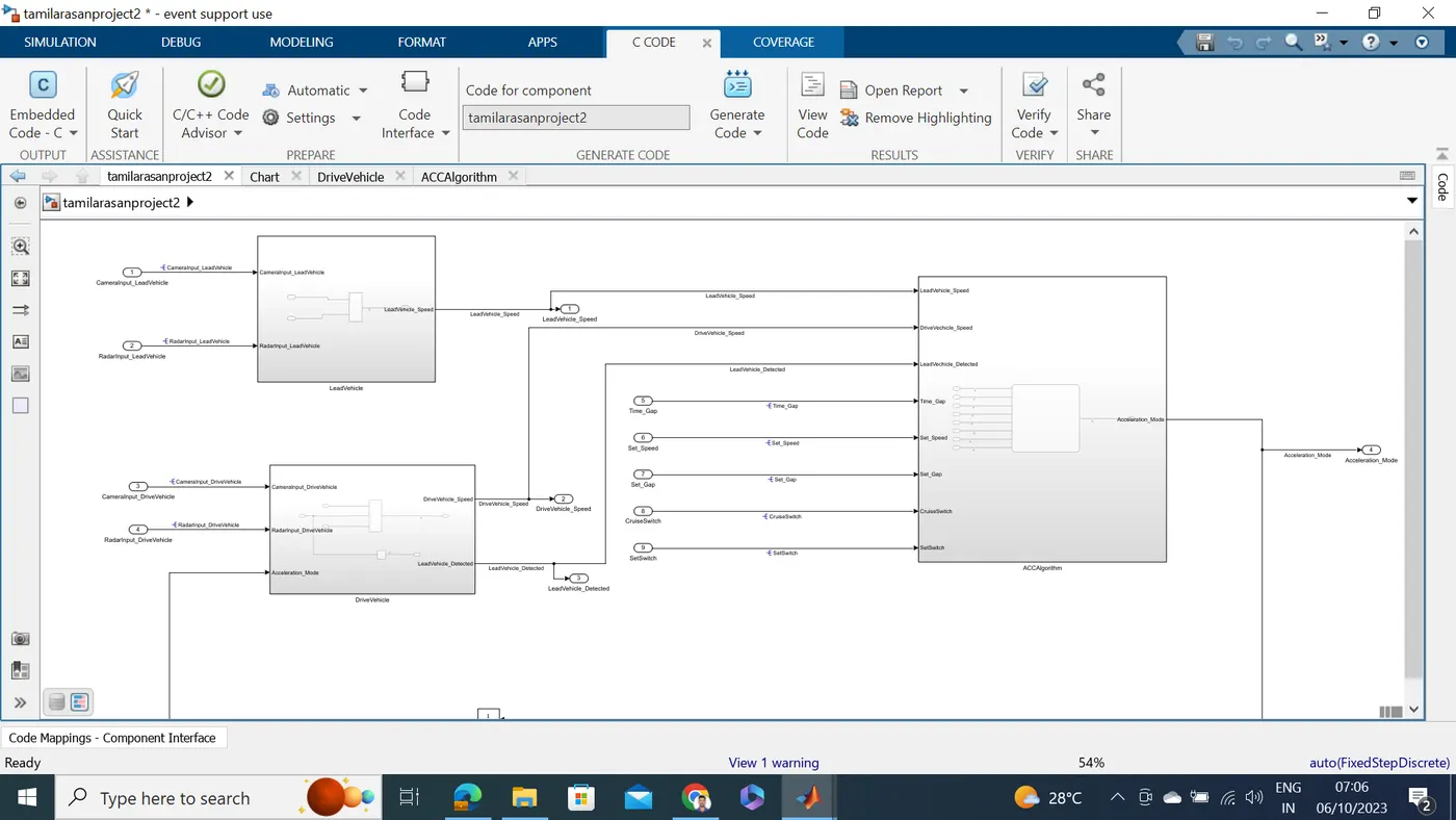
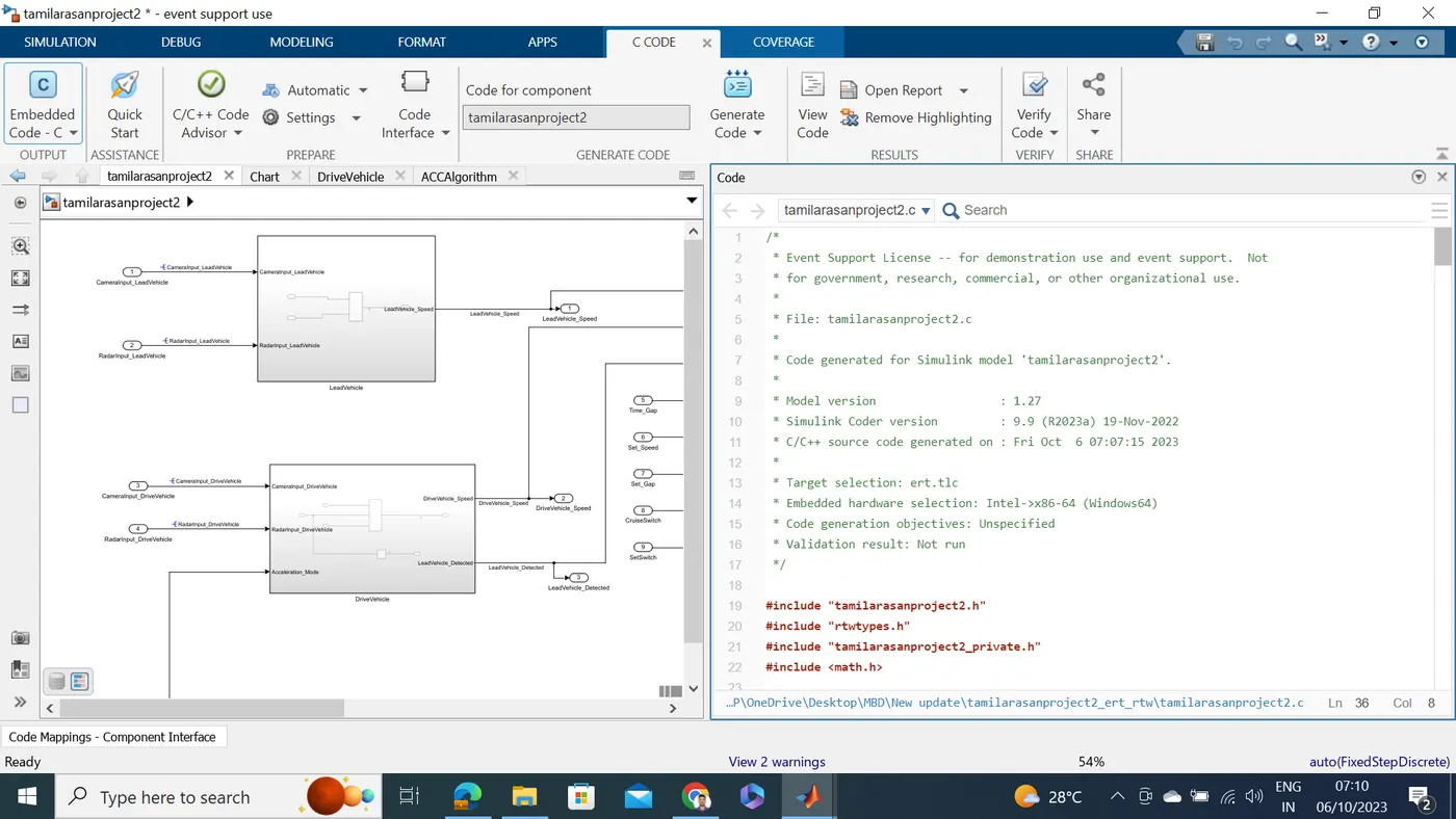
C Code
Results:
• After implementing the ACC model run the simulation. So the model is running successfully without any errors then the Adaptive Cruise Control works as per the requirement
• The model is running successfully without any error.
Conculation:
Hence. The Adaptive Cruise Control feature is developed as per the Requirement Document using MATLAB Simulink