Project 2 Adaptive Cruise Control
Pratik Mankar
MBD Live Batch 2
PROJECT NAME
ADAPTIVE CRUISE CONTROL
Requirement Project
Requirement 1– Lead Vehicle
- Lead Vehicle is a vehicle which is driving in the road ahead of our drive vehicle. Two input signals (Signal Name: CameraInput_LeadVehicle & RadarInput_LeadVehicle).
- Ideally sensor fusion techniques will be deployed to process & analyze data from camera & radar. For complexity reasons, let’s not adapt to any such algorithms.
- We can simply add both the radar & camera inputs & the corresponding output is read as Speed profile output (Signal Name: LeadVehicle_Speed).
- Speed data of the lead vehicle is critical in implementing the Adaptive Cruise Control algorithm.
Requirement 2 – Drive Vehicle
- Drive Vehicle is the vehicle driven by the user & this is the vehicle which has ACC algorithm in it.
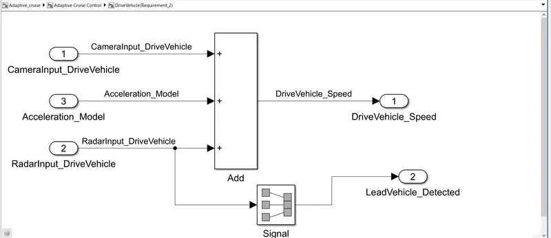
- Like the Lead Vehicle, Drive Vehicle algorithm also has 2 input signals (Signal Name: CameraInput_DriveVehicle, RadarInput_DriveVehicle) & one signal coming as an Input to this subsystem (Signal Name: Acceleration_Mode) – three inputs into this requirement in total.
- Like the above requirement, sensor fusion techniques will also be deployed here, for complexity reasons we are ignoring them.
- Two output signals come from this subsystem (Signal Name: DriveVehicle_Speed & LeadVehicle_Detected).
- Signal DriveVehicle_Speed is summation of three input signals mentioned above & LeadVehicle_Detected is renamed from Input Signal RadarInput_DriveVehicle by mere use of Signal Conversion block.
Requirement 3 – Adaptive Cruise Control Algorithm
- Adaptive Cruise Control feature has 3 major modes of operation: OFF Mode, STANDBY Mode & ON Mode. This particular requirement has to be implemented as state machine logic in Simulink.
- The input signals to this state machine system are (Signal Name: Time_Gap, Set_Speed, Set_Gap, CruiseSwitch, SetSwitch).
- Also, the output signals (Signal Name: DriveVehicle_Speed & LeadVehicle_Detected) from requirement-2 is fed back as an input signal into this state machine block.
- Additionally, output signal (Signal Name: LeadVehicle_Speed) from requirement-1 is given as an input signal to this state machine block as well.
- Output from this subsystem is a signal (Signal Name: Acceleration_Mode) which governs the vehicular speed of the drive vehicle which automatically adjusts its speed & velocity to match the lead vehicle.
Requirement 3a – ACC OFF MODE state logic
- This is the default state inside state machine logic. Output signal Acceleration_Mode is at value 0 in this state.
- This state is governed by input signal CruiseSwitch.
- If CruiseSwitch is equal to 1, state ACC STANDBY mode will get activated. If CruiseSwitch is equal to 0, state ACC OFF mode will get activated, from either ACC ON mode or ACC STANDBY mode
Requirement 3b – ACC STANDBY MODE state logic
- This is the second activated state inside state machine logic. Output signal Acceleration_Mode is at value 1 in this state.
- This state is governed by both input signals CruiseSwitch & SetSwitch.
- If CruiseSwitch is equal to 1, state ACC STANDBY mode will get activated. If CruiseSwitch is equal to 0, state ACC OFF mode will get activated, from either ACC ON mode or ACC STANDBY mode
- If SetSwitch is equal to 1, state ACC ON mode will get activated. If SetSwitch is equal to 0, state ACC STANDBY mode will get activated.
Requirement 3c – ACC ON MODE state logic
This state will be activated when input signal SetSwitch is equal to 1. There are 6 sub states to this state logic: They are:
- LeadVehicle_Detected_Follow (Default)
- LeadVehicle_Not_Detected
- LeadVehicle_Detected_Resume
- LeadVehicle_Not_Detected_Resume
- LeadVehicle_Speed_lessthan_Set_Speed
- LeadVehicle_Speed_equal_Set_Speed
Requirement 3c (i) – LeadVehicle_Detected_Follow (ACC ON MODE)
- This is the default sub state inside ACC ON MODE state. Output signal Acceleration_Mode is equal to 2.
- Condition to transit from LeadVehicle_Detected_Follow to LeadVehicle_Not_Detected; Input signal condition LeadVehicle_Detected == 0.
- Condition to transit from LeadVehicle_Detected_Follow to LeadVehicle_Speed_lessthan_Set_Speed; Input Signals condition (LeadVehicle_Detected == 1) && (LeadVehicle_Speed < Set_Speed) || (Time_Gap < Set_Gap).
Requirement 3c (ii) – LeadVehicle_Not_Detected (ACC ON MODE)
- Output signal Acceleration_Mode is equal to 1.
- Condition to transit from LeadVehicle_Not_Detected to LeadVehicle_Detected_Follow; Input signals condition [(LeadVehicle_Detected==1) && (DriveVehicle_Speed == Set_Speed) && (LeadVehicle_Speed >= Set_Speed) && (Time_Gap >= Set_Gap)]
- Condition to transit from LeadVehicle_Not_Detected to LeadVehicle_Speed_lessthan_Set_Speed; Input signals condition [(LeadVehicle_Detected == 1) && (LeadVehicle_Speed < Set_Speed) || (Time_Gap < Set_Gap)]
Requirement 3c (iii) – LeadVehicle_Detected_Resume (ACC ON MODE)
- Output signal Acceleration_Mode is equal to 3.
- Condition to transit from LeadVehicle_Detected_Resume to LeadVehicle_Detected_Follow; Input signals condition [(DriveVehicle_Speed == Set_Speed) && (LeadVehicle_Speed >= Set_Speed) && (Time_Gap >= Set_Gap)]
- Condition to transit from LeadVehicle_Detected_Resume to LeadVehicle_Not_Detected_Resume; Input signal condition LeadVehicle_Detected==0.
- Condition to transit from LeadVehicle_Detected_Resume to LeadVehicle_Speed_equal_Set_Speed; Input Signal condition [(DriveVehicle_Speed < Set_Speed) && (LeadVehicle_Speed > DriveVehicle_Speed) && (Time_Gap >= Set_Gap)]
Requirement 3c (iv) - LeadVehicle_Not_Detected_Resume (ACC ON MODE)
- Output signal Acceleration_Mode is equal to 1.
Requirement 3c (v) - LeadVehicle_Speed_lessthan_Set_Speed (ACC ON MODE)
- Output signal Acceleration_Mode is equal to 4.
- Condition to transit from LeadVehicle_Speed_lessthan_Set_Speed to LeadVehicle_Not_Detected; Input signal condition [(LeadVehicle_Detected == 0) && (DriveVehicle_Speed == Set_Speed)]
- Condition to transit from LeadVehicle_Speed_lessthan_Set_Speed to LeadVehicle_Speed_equal_Set_Speed; Input signals condition [((LeadVehicle_Speed*1.25>=DriveVehicle_Speed) && (LeadVehicle_Speed * 0.75<=DriveVehicle_Speed)) && (DriveVehicle_Speed < Set_Speed) && ((Time_Gap<=1.25*Set_Gap) && (Time_Gap >=0.75*Set_Gap))]
Requirement 3c (vi) - LeadVehicle_Speed_equal_Set_Speed (ACC ON MODE)
- Output signal Acceleration_Mode is equal to 5.
- Condition to transit from LeadVehicle_Speed_equal_Set_Speed to LeadVehicle_Not_Detected_Resume; Input signal conditions is [(LeadVehicle_Detected == 0) || (DriveVehicle_Speed <= Set_Speed)]
- Condition to transit from LeadVehicle_Speed_equal_Set_Speed to LeadVehicle_Detected_Resume; Input signal conditions [(DriveVehicle_Speed < Set_Speed) && (LeadVehicle_Speed > DriveVehicle_Speed) || (Time_Gap >= Set_Gap)]
- Condition to transit from LeadVehicle_Speed_equal_Set_Speed to LeadVehicle_Speed_lessthan_Set_Speed; Input signals conditions [(LeadVehicle_Speed<Set_Speed) && (LeadVehicle_Speed<DriveVehicle_Speed) || (Time_Gap == 0.75*Set_Gap)]
AIM
To develop an MBD-compliant Adaptive Cruise Control feature as per the provided requirement document using MATLAB Simulink.
OBJECTIVE
- Developing Adaptive Cruise Control feature as per the Requirement Document using MATLAB Simulink.
- Follow all the MBD related processes: Requirement Tagging & Traceability, SLDD creation, Configuration Parameter changes, Model Advisor check & Code Generation.
- In Configuration Parameters: enable “Support Floating Numbers” under Code Generation settings.
- Use Embedded Coder to generate the code.
- If choosing code generation, Storage class for Input signals: ImportedExtern; Storage class for Output signal: Export to File; Storage class for local signals: localizable; Storage class for calibration signals: Const.
- Choose sample time for all signals as 0.01s
THEROY
The main reason behind cruise control technology is to make driver relax behind the wheel. Because of this, their driving experience becomes safer, thrilling and also saves the fuel consumption. By monitoring other vehicles and objects on the road, adaptive cruise control enables a safe and comfortable driving experience. It helps the driver keep a steady vehicle speed at a given moment. The driver can set their preference regarding certain factors, such as the distance to the car in front, driving mode. Together with information about speed limits, road curvature, accidents data and more, these choices influence the automatically selected speed. As less expensive sensors reached the market, adaptive cruise control is steadily becoming a standard feature in new vehicles today.
In slow-moving traffic, it automatically stops or starts vehicle movement under driver supervision. The car will brake and accelerate on its own, while maintaining a safe distance from the vehicle in front. Intelligent cruise control can automatically adjust the set speed to the newly detected speed limit when the driver is passing a speed limit sign. This is done by fusing camera observation and map data to provide reliable speed restriction information.
Radar-based systems work by placing radar-based sensors on or around plastic fascia’s to detect your vehicle's surroundings. Each radar sensor works together to create a comprehensive picture of the vehicle's proximity to other cars or potentially hazardous objects. This type of sensor can look different depending on the design and model of the car.
ACC that uses sensory data to predict the actions of neighbouring vehicles. This means that your car might slow down to brake for another vehicle suddenly switching lanes and, in doing so, promotes passenger safety.
STEP 1
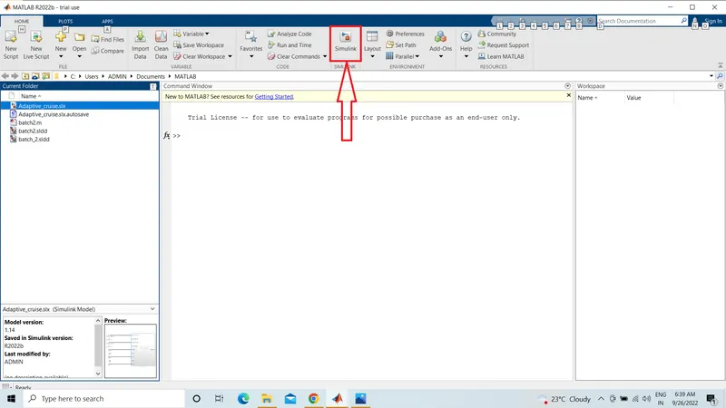
First open the matlab and after that open simulink shown in below
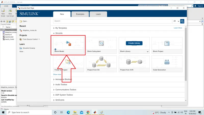
Here click the Blank Model to Create a New File
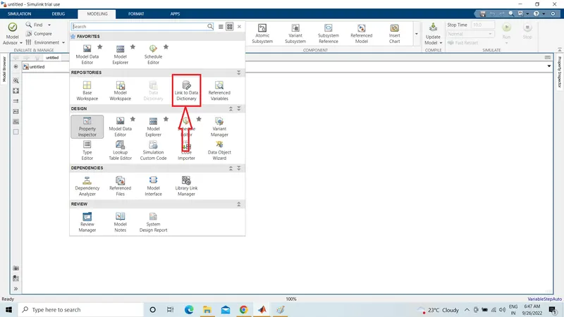
First given Input and Output signals should be creating in a SLDD file
- we go to click and select Modelling Tab there is a open a New Window and Click on Link to Data Dictionary.
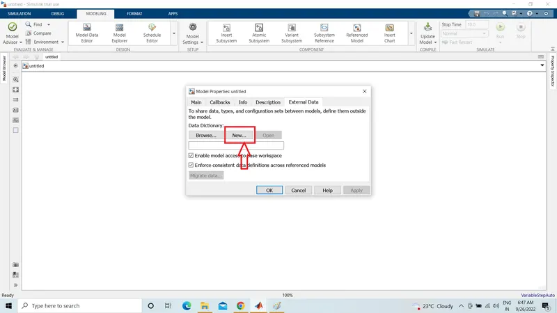
Creating model properties select new and create a SLDD File
Name of File Batch_2SLDD
STEP 2
- Create a sldd file according to the data given in question.
- modeling > link to data dictionary > new( create new sldd file)
- Then access the sldd file from modeling> model explorer>Adaptive_cruise_control> expand external data> design data( input signal and parameters there)
After Creating SLDD File See in Below Figure.
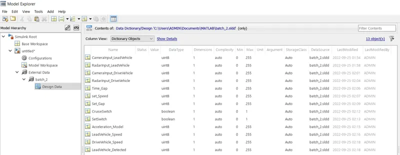
Signals & Calibration Data List
|
Signal / Calibration Name |
Signal Type |
Data Type |
Dimension |
Min |
Max |
Initial Value |
Units |
|
CameraInput_LeadVehicle |
Input |
Uint8 |
1 |
0 |
255 |
- |
- |
|
RadarInput_LeadVehicle |
Input |
Uint8 |
1 |
0 |
255 |
- |
- |
|
CameraInput_DriveVehicle |
Input |
Uint8 |
1 |
0 |
255 |
- |
- |
|
RadarInput_DriveVehicle |
Input |
Uint8 |
1 |
0 |
255 |
- |
- |
|
Time_Gap |
Input |
Uint8 |
1 |
0 |
255 |
- |
- |
|
Set_Speed |
Input |
Uint8 |
1 |
0 |
255 |
- |
- |
|
Set_Gap |
Input |
Uint8 |
1 |
0 |
255 |
- |
- |
|
CruiseSwitch |
Input |
Boolean |
1 |
0 |
1 |
- |
- |
|
SetSwitch |
Input |
Boolean |
1 |
0 |
1 |
- |
- |
|
Acceleration_Mode |
Output |
Uint8 |
1 |
0 |
255 |
- |
- |
|
LeadVehicle_Speed |
Output |
Uint8 |
1 |
0 |
255 |
- |
- |
|
DriveVehicle_Speed |
Output |
Uint8 |
1 |
0 |
255 |
- |
- |
|
LeadVehicle_Detected |
Output |
Uint8 |
1 |
0 |
255 |
- |
- |
STEP 3
DEVELOPMENT OF ADAPTIVE CRUISE CONTROL SIMULINK MODEL
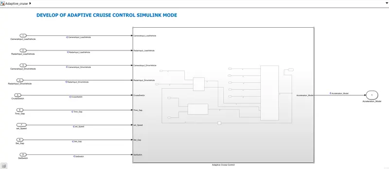
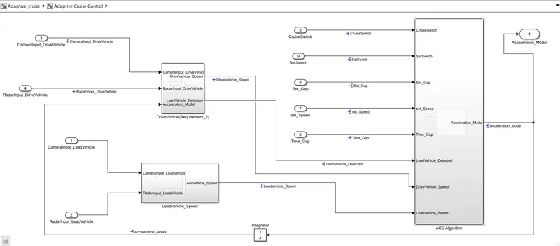
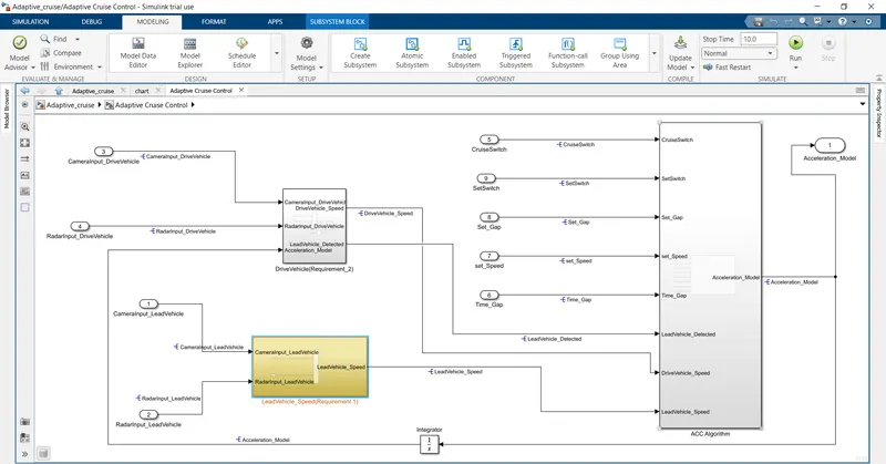
Adaptive_Cruise_Control_Mode subsystem consist of Three Requirement Subsystems, Lead Vehicle Subsystem(Requirement_1), Drive Vehicle subsystem(Requirement_2) & Adaptive Cruise Control Subsystem(Requirement_3).
SIMULATION
There are some steps to be followed to develop the model of Adaptive cruise control. First of all changed the model settings to MBD compliance changes. MBD settings includes solver type to be changed to Fixed-step discrete(no continuous states) and fixed step size to 0.01s. Under the code generation the target file is changed to Embedded Codder.
STEP 4
Requirement 1– Lead Vehicle
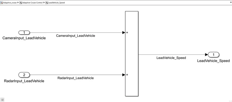
- Lead Vehicle is a vehicle which is driving in the road ahead of our drive vehicle. Two input signals (Signal Name: CameraInput_LeadVehicle & RadarInput_LeadVehicle).
- Ideally sensor fusion techniques will be deployed to process & analyze data from camera & radar. For complexity reasons, let’s not adapt to any such algorithms.
- We can simply add both the radar & camera inputs & the corresponding output is read as Speed profile output (Signal Name: LeadVehicle_Speed).
- Speed data of the lead vehicle is critical in implementing the Adaptive Cruise Control algorithm.
STEP 5
Requirement 2 – Drive Vehicle
- Drive Vehicle is the vehicle driven by the user & this is the vehicle which has ACC algorithm in it.
- Like the Lead Vehicle, Drive Vehicle algorithm also has 2 input signals (Signal Name: CameraInput_DriveVehicle, RadarInput_DriveVehicle) & one signal coming as an Input to this subsystem (Signal Name: Acceleration_Mode) – three inputs into this requirement in total.
- Like the above requirement, sensor fusion techniques will also be deployed here, for complexity reasons we are ignoring them.
- Two output signals come from this subsystem (Signal Name: DriveVehicle_Speed & LeadVehicle_Detected).
- Signal DriveVehicle_Speed is summation of three input signals mentioned above & LeadVehicle_Detected is renamed from Input Signal RadarInput_DriveVehicle by mere use of Signal Conversion block.
 b
b
STEP 6
Requirement 3 – Adaptive Cruise Control Algorithm
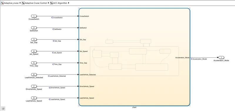
- Adaptive Cruise Control feature has 3 major modes of operation: OFF Mode, STANDBY Mode & ON Mode. This particular requirement has to be implemented as state machine logic in Simulink.
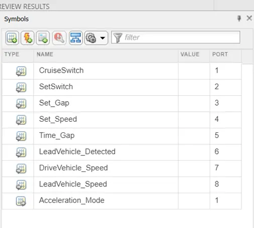
- The input signals to this state machine system are (Signal Name: Time_Gap, Set_Speed, Set_Gap, CruiseSwitch, SetSwitch).
- Also, the output signals (Signal Name: DriveVehicle_Speed & LeadVehicle_Detected) from requirement-2 is fed back as an input signal into this state machine block.
- Additionally, output signal (Signal Name: LeadVehicle_Speed) from requirement-1 is given as an input signal to this state machine block as well.
- Output from this subsystem is a signal (Signal Name: Acceleration Mode) which governs the vehicular speed of the drive vehicle which automatically adjusts its speed & velocity to match the lead vehicle.
Requirement 3a – ACC OFF MODE State Logic
- This is the default state inside state machine logic. Output signal Acceleration_Mode is at value 0 in this state.
- This state is governed by input signal CruiseSwitch.
- If CruiseSwitch is equal to 1, state ACC STANDBY mode will get activated. If CruiseSwitch is equal to 0, state ACC OFF mode will get activated, from either ACC ON mode or ACC STANDBY mode.
Requirement 3b – ACC STANDBY MODE State Logic.
- This is the second activated state inside state machine logic. Output signal Acceleration_Mode is at value 1 in this state.
- This state is governed by both input signals CruiseSwitch & SetSwitch.
- If CruiseSwitch is equal to 1, state ACC STANDBY mode will get activated. If CruiseSwitch is equal to 0, state ACC OFF mode will get activated, from either ACC ON mode or ACC STANDBY mode.
- If SetSwitch is equal to 1, state ACC ON mode will get activated. If SetSwitch is equal to 0, state ACC STANDBY mode will get activated.
Requirement 3c – ACC ON MODE State Logic.
This state will be activated when input signal SetSwitch is equal to 1. There are 6 sub states to this state logic: They are.
- LeadVehicle_Detected_Follow (Default)
- LeadVehicle_Not_Detected
- LeadVehicle_Detected_Resume
- LeadVehicle_Not_Detected_Resume
- LeadVehicle_Speed_lessthan_Set_Speed
- LeadVehicle_Speed_equal_Set_Speed
Requirement 3c (i) – LeadVehicle_Detected_Follow (ACC ON MODE).
- This is the default sub state inside ACC ON MODE state. Output signal Acceleration_Mode is equal to 2.
- Condition to transit from LeadVehicle_Detected_Follow to LeadVehicle_Not_Detected; Input signal condition LeadVehicle_Detected == 0.
- Condition to transit from LeadVehicle_Detected_Follow to LeadVehicle_Speed_lessthan_Set_Speed; Input Signals condition (LeadVehicle_Detected == 1) && (LeadVehicle_Speed < Set_Speed) || (Time_Gap < Set_Gap).
Requirement 3c (ii) – LeadVehicle_Not_Detected (ACC ON MODE).
- Output signal Acceleration_Mode is equal to 1.
- Condition to transit from LeadVehicle_Not_Detected to LeadVehicle_Detected_Follow; Input signals condition [(LeadVehicle_Detected==1) && (DriveVehicle_Speed == Set_Speed) && (LeadVehicle_Speed >= Set_Speed) && (Time_Gap >= Set_Gap)]
- Condition to transit from LeadVehicle_Not_Detected to LeadVehicle_Speed_lessthan_Set_Speed; Input signals condition [(LeadVehicle_Detected == 1) && (LeadVehicle_Speed < Set_Speed) || (Time_Gap < Set_Gap)]
Requirement 3c (iii) – LeadVehicle_Detected_Resume (ACC ON MODE).
- Output signal Acceleration_Mode is equal to 3.
- Condition to transit from LeadVehicle_Detected_Resume to LeadVehicle_Detected_Follow; Input signals condition [(DriveVehicle_Speed == Set_Speed) && (LeadVehicle_Speed >= Set_Speed) && (Time_Gap >= Set_Gap)]
- Condition to transit from LeadVehicle_Detected_Resume to LeadVehicle_Not_Detected_Resume; Input signal condition LeadVehicle_Detected==0.
- Condition to transit from LeadVehicle_Detected_Resume to LeadVehicle_Speed_equal_Set_Speed; Input Signal condition [(DriveVehicle_Speed < Set_Speed) && (LeadVehicle_Speed > DriveVehicle_Speed) && (Time_Gap >= Set_Gap)]
Requirement 3c (iv) - LeadVehicle_Not_Detected_Resume (ACC ON MODE).
- Output signal Acceleration_Mode is equal to 1.
Requirement 3c (v) - LeadVehicle_Speed_lessthan_Set_Speed (ACC ON MODE).
- Output signal Acceleration_Mode is equal to 4.
- Condition to transit from LeadVehicle_Speed_lessthan_Set_Speed to LeadVehicle_Not_Detected; Input signal condition [(LeadVehicle_Detected == 0) && (DriveVehicle_Speed == Set_Speed)]
- Condition to transit from LeadVehicle_Speed_lessthan_Set_Speed to LeadVehicle_Speed_equal_Set_Speed; Input signals condition [((LeadVehicle_Speed*1.25>=DriveVehicle_Speed) && (LeadVehicle_Speed * 0.75<=DriveVehicle_Speed)) && (DriveVehicle_Speed < Set_Speed) && ((Time_Gap<=1.25*Set_Gap) && (Time_Gap >=0.75*Set_Gap))]
Requirement 3c (vi) - LeadVehicle_Speed_equal_Set_Speed (ACC ON MODE).
- Output signal Acceleration_Mode is equal to 5.
- Condition to transit from LeadVehicle_Speed_equal_Set_Speed to LeadVehicle_Not_Detected_Resume; Input signal conditions is [(LeadVehicle_Detected == 0) || (DriveVehicle_Speed <= Set_Speed)]
- Condition to transit from LeadVehicle_Speed_equal_Set_Speed to LeadVehicle_Detected_Resume; Input signal conditions [(DriveVehicle_Speed < Set_Speed) && (LeadVehicle_Speed > DriveVehicle_Speed) || (Time_Gap >= Set_Gap)]
- Condition to transit from LeadVehicle_Speed_equal_Set_Speed to LeadVehicle_Speed_lessthan_Set_Speed; Input signals conditions [(LeadVehicle_Speed<Set_Speed) && (LeadVehicle_Speed<DriveVehicle_Speed) || (Time_Gap == 0.75*Set_Gap)]
Symbol Pane
STEP 7
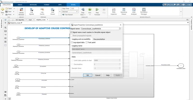
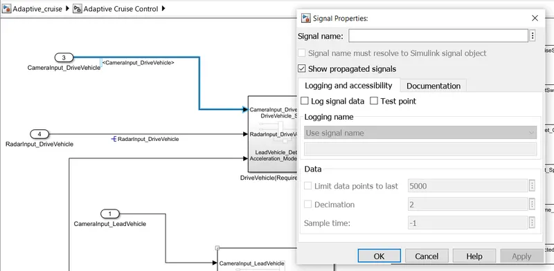
The next step is solve signals and propagate them.
- For signal resolve : select signal>right click signal > properties >signal name >check signal name
must resolve to simulink object>ok
SETP 8
propogation of signal
select signal>right click signal > properties > check show propogated signals >ok
SETP 9
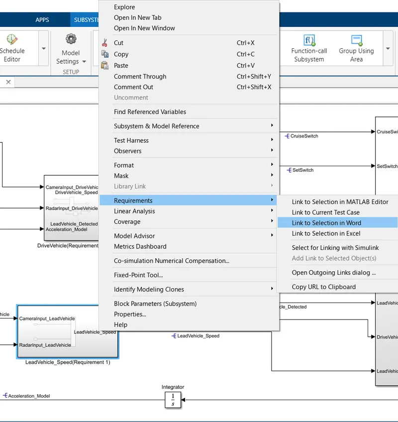
Tagging of the system
select Lead_Vehicle(Requirement_1) subsystem right-clicks> requirements > link to selection in word
then
word file and information will be open of that subsystem. if we click on it
TAGGING IS DONE
Lead_Vehicle(Requirement_1) subsystem Tagging
same do for remaining Drive vehicle subsystem(Requirement_2) & Adaptive Cruise Control subsystem(Requirement_3).
Drive vehicle subsystem(Requirement_2) Tagging
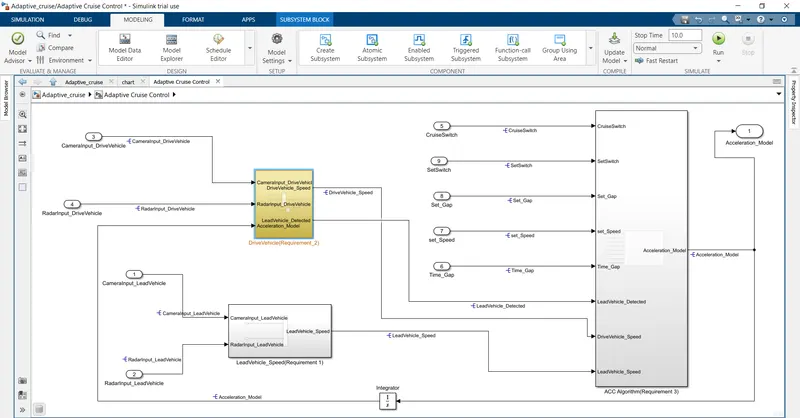
Adaptive Cruise Control subsystem(Requirement_3) Tagging
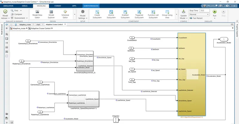
STEP 10
Now from model setting> solver configuration> type-fixed-step >solver- discrete solver>stepsize= 0.01seconds.
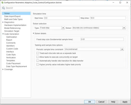
Code Generatin
code generation>system target file >ert.tlc embedded codder.
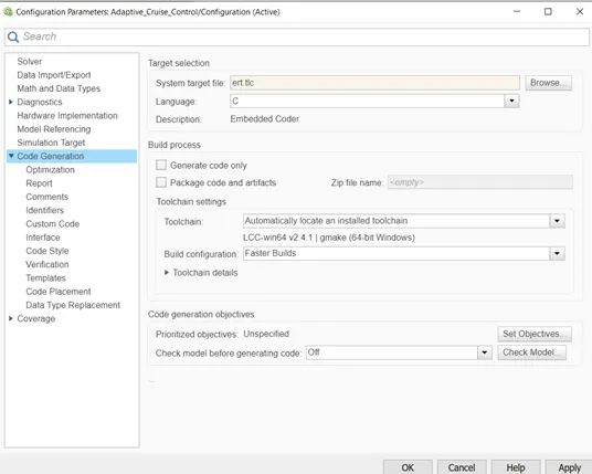
STEP 11
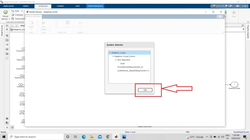
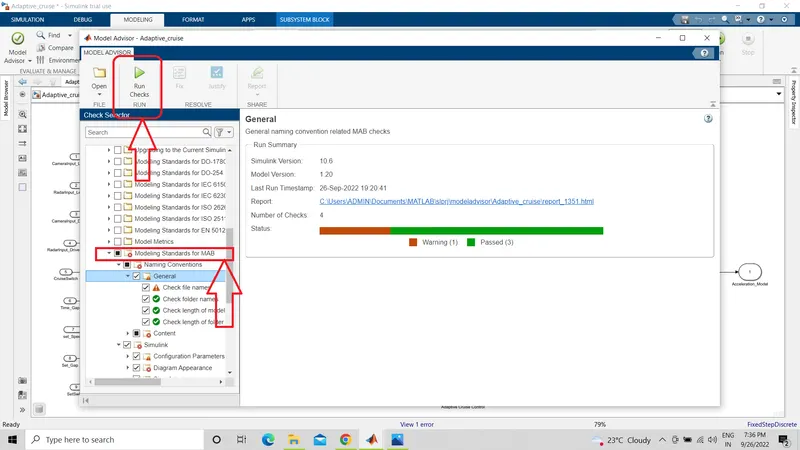
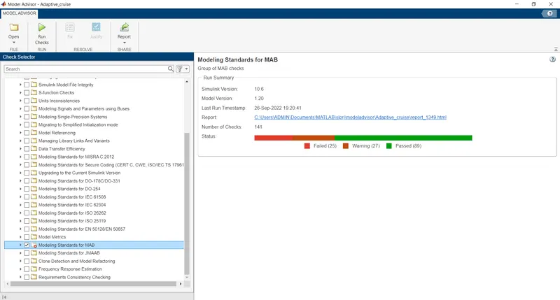
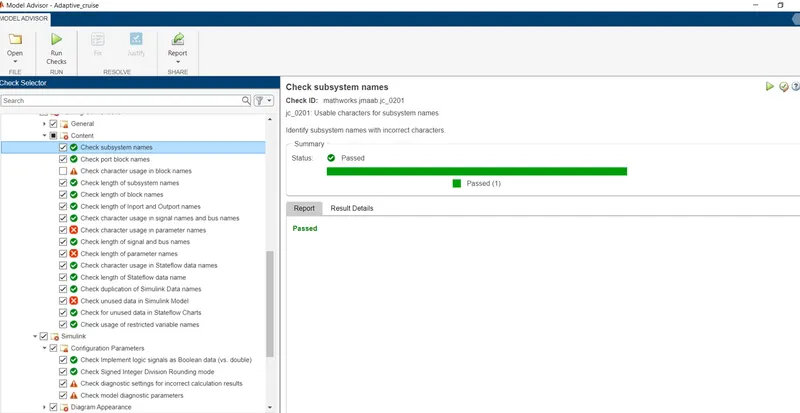
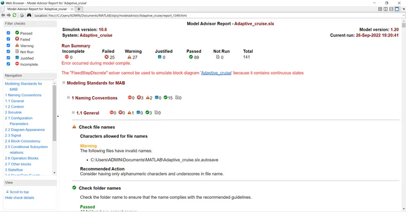
Get a Model Advisor Check>by task>ony check modelling standards with MAB>Run selected checks
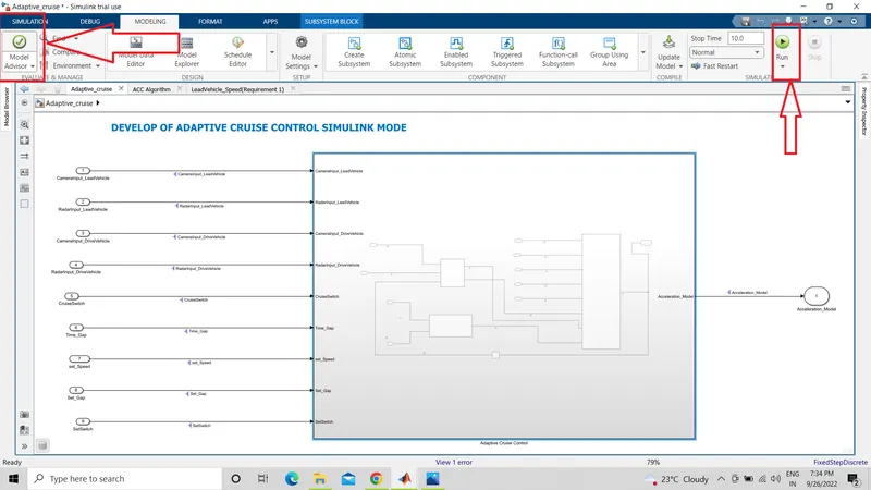
STEP 12
Model advisor Report
STEP 13
Generate Code for Model:
apps> embedded coder>generate code
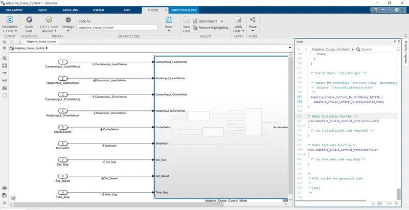
Generated code
/* Model step function */
void Adaptive_Cruise_Control_step(void)
{
  uint8_T DriveVehicle_Speed;
  uint8_T LeadVehicle_Speed;

  /* Sum: '/Add' incorporates:
   *  Inport: '/CameraInput_DriveVehicle'
   *  Inport: '/RadarInput_DriveVehicle'
   *  UnitDelay: '/Unit Delay'
   */
  DriveVehicle_Speed = (uint8_T)((uint32_T)(uint8_T)((uint32_T)
    Adaptive_Cruise_Control_U.CameraInput_DriveVehicle +
    Adaptive_Cruise_Control_DW.UnitDelay_DSTATE) +
    Adaptive_Cruise_Control_U.RadarInput_DriveVehicle);

  /* Sum: '/Add' incorporates:
   *  Inport: '/CameraInput_LeadVehicle'
   *  Inport: '/RadarInput_LeadVehicle'
   */
  LeadVehicle_Speed = (uint8_T)((uint32_T)
    Adaptive_Cruise_Control_U.CameraInput_LeadVehicle +
    Adaptive_Cruise_Control_U.RadarInput_LeadVehicle);

  /* Chart: '/ACCLogic' incorporates:
   *  Inport: '/CruiseSwitch'
   *  Inport: '/SetSwitch'
   */
  if (Adaptive_Cruise_Control_DW.is_active_c3_Adaptive_Cruise_Co == 0U) {
    Adaptive_Cruise_Control_DW.is_active_c3_Adaptive_Cruise_Co = 1U;
    Adaptive_Cruise_Control_DW.is_c3_Adaptive_Cruise_Control =
      Adaptive_Cruise_IN_Acc_Off_Mode;

    /* Outport: '/Acceleration_Mode' */
    Adaptive_Cruise_Control_Y.Acceleration_Mode = 0U;
  } else {
    switch (Adaptive_Cruise_Control_DW.is_c3_Adaptive_Cruise_Control) {
     case Adaptive_Cruise_IN_Acc_Off_Mode:
      /* Outport: '/Acceleration_Mode' */
      Adaptive_Cruise_Control_Y.Acceleration_Mode = 0U;
      if (Adaptive_Cruise_Control_U.CruiseSwitch) {
        Adaptive_Cruise_Control_DW.is_c3_Adaptive_Cruise_Control =
          Adaptive_Cr_IN_Acc_Standby_mode;

        /* Outport: '/Acceleration_Mode' */
        Adaptive_Cruise_Control_Y.Acceleration_Mode = 1U;
      }
      break;

     case Adaptive_Cruise__IN_Acc_On_mode:
      Adaptive_Cruise_Con_Acc_On_mode(&DriveVehicle_Speed, &LeadVehicle_Speed);
      break;

     default:
      /* Outport: '/Acceleration_Mode' */
      /* case IN_Acc_Standby_mode: */
      Adaptive_Cruise_Control_Y.Acceleration_Mode = 1U;
      if (!Adaptive_Cruise_Control_U.CruiseSwitch) {
        Adaptive_Cruise_Control_DW.is_c3_Adaptive_Cruise_Control =
          Adaptive_Cruise_IN_Acc_Off_Mode;

        /* Outport: '/Acceleration_Mode' */
        Adaptive_Cruise_Control_Y.Acceleration_Mode = 0U;
      } else {
        if (Adaptive_Cruise_Control_U.SetSwitch) {
          Adaptive_Cruise_Control_DW.is_c3_Adaptive_Cruise_Control =
            Adaptive_Cruise__IN_Acc_On_mode;
          Adaptive_Cruise_Control_DW.is_Acc_On_mode =
            IN_LeadVehicle_Detected_Follow;

          /* Outport: '/Acceleration_Mode' */
          Adaptive_Cruise_Control_Y.Acceleration_Mode = 2U;
        }
      }
      break;
    }
  }

  /* End of Chart: '/ACCLogic' */

  /* Update for UnitDelay: '/Unit Delay' incorporates:
   *  Outport: '/Acceleration_Mode'
   */
  Adaptive_Cruise_Control_DW.UnitDelay_DSTATE =
    Adaptive_Cruise_Control_Y.Acceleration_Mode;
}

/* Model initialize function */
void Adaptive_Cruise_Control_initialize(void)
{
  /* (no initialization code required) */
}

/* Model terminate function */
void Adaptive_Cruise_Control_terminate(void)
{
  /* (no terminate code required) */
}

/*
 * File trailer for generated code.
 *
 * [EOF]
 */
Procedure
As per the Requirement document, implemented the Adaptive Cruise Control feature.
Lead vehicle
- To detect the lead vehicle speed, simply added both the radar & camera inputs & the corresponding output is read as Speed profile output.
Drive Vehicle
- To regulate the "Drive Vehicle speed", as per the Requirement Dicument added CameraInput, RadarInput & Acceleration_Mode feedback from ACC Algorithm.
- To detect the Lead vehicle, RadarInput is converted using "Signal Conversion Block".
- To avoid the algebraic error "Unit delay" block is used for the Acceleration_Mode feedback.
ACC Algorithm
- Adaptive Cruise Control feature has 3 major modes of operation: OFF Mode, STANDBY Mode & ON Mode. This particular requirement has to be implemented as state machine logic in Simulink.
- The input signals to this state machine system are (Signal Name: Time_Gap, Set_Speed, Set_Gap, CruiseSwitch, SetSwitch).
- Also, the output signals (Signal Name: DriveVehicle_Speed & LeadVehicle_Detected) from requirement-2 is fed back as an input signal into this state machine block.
- Additionally, output signal (Signal Name: LeadVehicle_Speed) from requirement-1 is given as an input signal to this state machine block as well.
- Output from this subsystem is a signal (Signal Name: Acceleration_Mode) which governs the vehicular speed of the drive vehicle which automatically adjusts its speed & velocity to match the lead vehicle.
CONCLUSION
The simulink model for adative cruise control was developed under following the requirements given. we have Developed Adaptive Cruise Control feature as per the Requirement Document using MATLAB Simulink.
Link
https://drive.google.com/drive/folders/1rlZYk8sF67gEZyy-PO9WzNizSyYkyUgY?usp=sharing