Project 2
SOURCE CURRENT THD-
To make the power factor at input side of AC-DC rectifier the input current should have to posses two condition-
1) Input current should be sinusoidal.
2) Input current should be in phase with supply voltage.
So, to make these two conditions should follow i have made the simulation of single phase full bridge rectifier with output voltage as voltage control and input current as current control.So, with change in load voltage how the input currrent will behave we will see with simulation diagram.
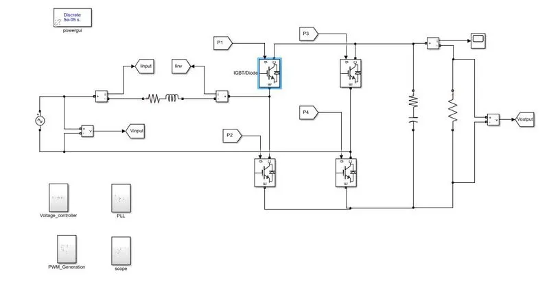
Taken parameters
(V_input=230V rms.
f=50Hz.
Output voltage reference is takeen as 400 Volt)
According to IEEE standards the grid voltage and current THD should be less than or equal to 5%.
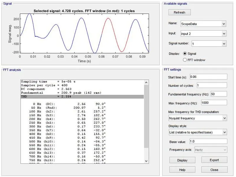
As we can see from the above from FFT analysis the THD in input current is 2.35%.
INPUT POWER FACTOR CALCULATION-
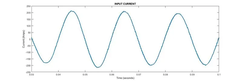
As the input current waveform is exactly sinusoidal in steady state so the distortion factor(g) is equal to 1.
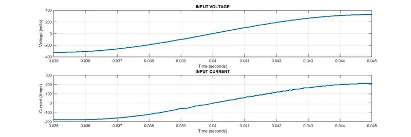
Input power factor= Distortion factor × Displacement power factor.
From the above figure if we compare the zero crossing of the supply voltage and supply current we can see approximatelly both the waveform crossing zero at same instant so the displacement power factor is 1.
so, the INPUT POWER FACTOR BECOMES UNITY.
REGULATION OF LOAD VOLTAGE WITH CHANGE IN REFERENCE VOLTAGE AND EFFECT ON INPUT/GRID SIDE OF CONVERTER-
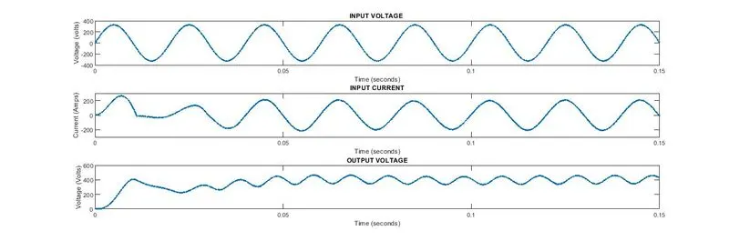
So here with change in the load voltage the effect on input side current will we seen as, i have taken the reference voltage is 400 volt the actual value is tracking 400 volt in steady state with some ripple.also the input/grid side current is nearlly sinusoidal which makes the input power factor is nearlly unity.
CASCADED CONTROL STRUCTURE
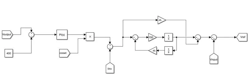
In this circuit cascaded control structure has been shown with outer is voltage control and inner is current control, the change in output voltage is compared with the actual value of voltage we want which is refence value of input side current of rectifier.Since the input side current has to be sinusidal for unity power factor so a proportional resonant controller is used to track the sinusoidal quantities the output of inner control used to provide reference for switching of unipolar PWM.
SIMULINK FILE IS ATTACHED IN BROWSE SECTION.