Answer:-

1) Driver Block:-
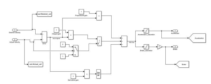
>Input to this system is desired velocity and actual velocity.

>Driver subsystem is actually a PID controller.

>Error signal is calculated by comparing the desired and actual velocity.

>This error signal is then is then fed to proportional, integral and derivative controller.

>To avoid the unwanted error due to integrator, the external reset is done whenever the actual velocity is zero.

>Proportional gain is given as 0.75, Integral gain as 0.03 and Differential gain as 0.

>The PID output is from -1 to 1. If the output is between 0 to 1 it is given as accelerator command and if the output is between -1 to 0 it is multiplied with -1 and is given as brake command.

>The output of this subsystem is accelerator and brake command.
2) Powertrain:-
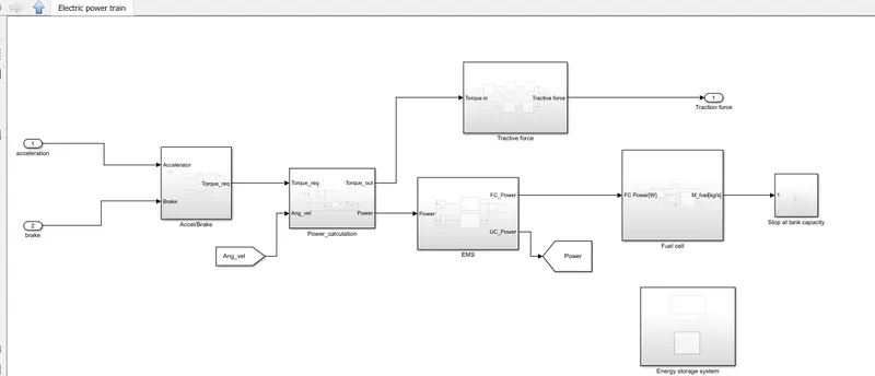
>Input to the subsystem is accelerator and brake commands.

>This consists of controller, torque/power, tractive force, Energy management system, fuel cell system, H2 consumption and energy storage system.

>The output of the subsystem is tractive force, hydrogen consumption, SOC of battery and ultracapacitor.
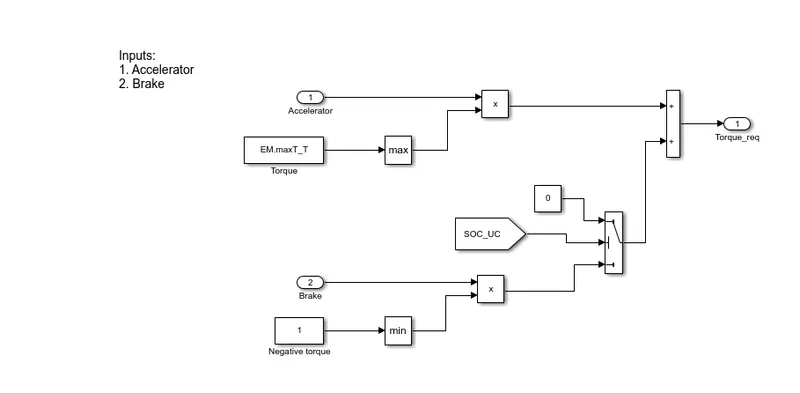
Power Calculation:-
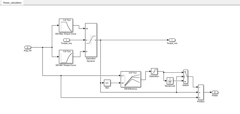
>The input of this subsystem is torque request and output is Torque out and power demand.

>According to the Electrical machine angular velocity, the maximum and minimum torque is set by using lookup table (Max torque curve and Min torque curve) and if the torque request is within this limit, then the torque is given as output.

>The power is calculated from the Torque and angular velocity.

P = T*w
3)Energy Management System(EMS):-
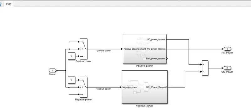
>Energy management system is used for load sharing among the energy devices to efficiently operate the vehicle by operating in the optimum region of Battery, ultracapacitor and fuel cell.

>The input to the subsystem is Power demand.

>The output is Fuel cell power, ultracapacitor power and Battery power.

>If the power demand is positive, that is used for propulsion.

>If the power demand is negative, that is used for regeneration.

>The load demand sharing algorithm has to be used to deliver the load.
4)Tractive Force:-
Fuel Cell:-
Ultracapacitor:-
Results:-
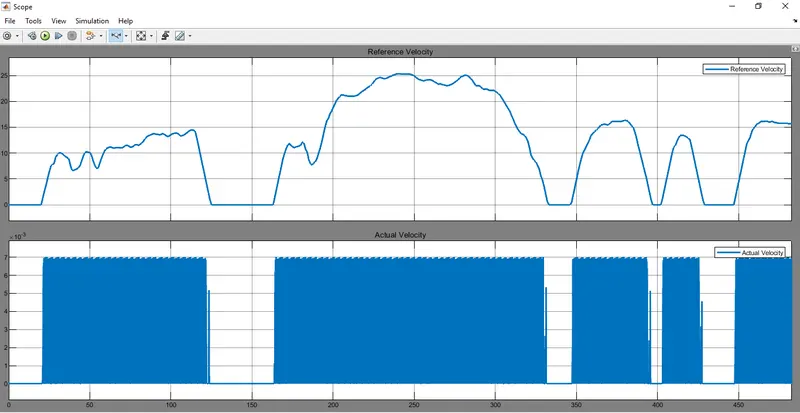
Conclusion:-


 The Fuel cell electric vehicle has designed and modelled in simulink environment. The model has worked as per desired with same actual and desired velocity. The EMS working has analysed and was able to support all type of power demands and regenrtive braking by keeping all ESSs in its rated operating range. The fuel cell along with battery and UC have a great performance comparing to individula performance as each of them have its own properties. The fuel and air consumption of the Fuel cell has anlaysed and is minimum compared to fuel cell alone vehicle and also having higher dynamic performance.