Project 2
Project 2
Model & Design a Proposed PEB Warehouse using STAAD. Pro with following Technical specification.
Aim: Designing and modeling a suggested PEB warehouse utilizing STAAD Pro.
Introduction: we create the design for the PEB warehouse based on provided descriptions, material data, and specifications.
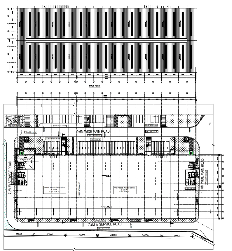
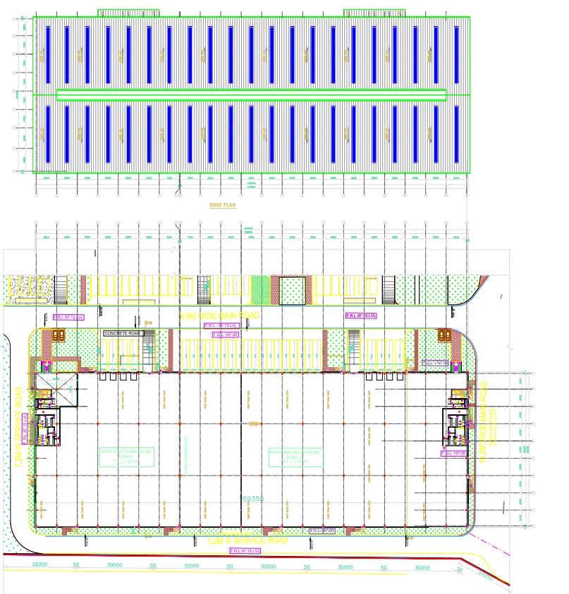
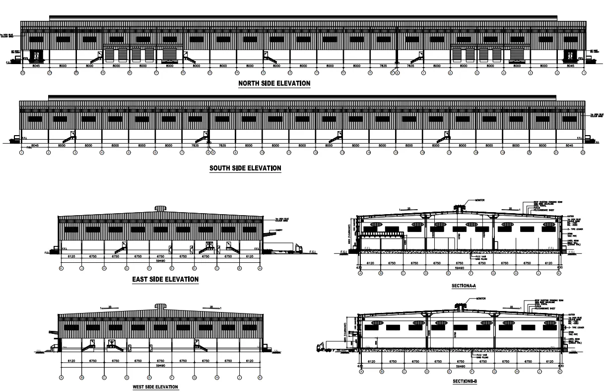
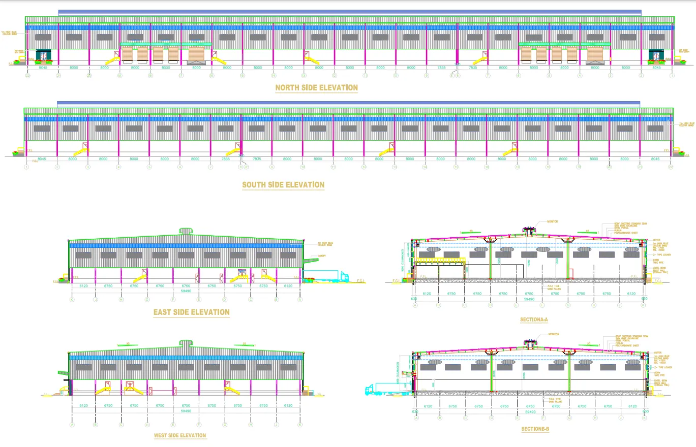
Plan view given: The plan view and elevation views of the PEB are displayed below.
 *
* 
 *
*
Procedure:
Step 1:
> Open STAAD Pro software and start a new file. In the Geometry Tab, build the model using Nodes and Beam commands.
Step 2:
> Navigate to the Specification Tab and generate sections for the model, assigning them accordingly.
Step 3:
> In the Specification Tab, establish a Moment Release and assign it to the Gable End Columns.
Step 4:
> Within the Support Tab, generate a Fixed Support and assign it to all columns.
Step 5 - Load Calculation:
> Seismic Load:
- Zone Factor: 0.16 (Zone III)
- Response Reduction: 4 (Ordinary Moment Resisting Frames)
- Importance Factor: 1.0 (Category 4)
- Soil Type: 1.0 (Hard Soil – As per Staad)
- Type of Structure: 3.0 (Steel Moment Resisting Frames - As per Staad)
- Consider 25% of Live Load on the roof for seismic forces.
- Consider 100% of collateral load on the roof for seismic forces.
- Consider 50% of (Live load + Collateral load) on the mezzanine floor for seismic forces.
- Consider 100% of Dead load for seismic forces.
> Dead Load:
1. Self-weight assigned to the entire structure.
2. Purlin - 10 Kg/m2 and 10 kg/m2 for roof sheeting.
- Total: 120 Kg/m2 on the main rafter (1.2 kN/m2) and 0.6 kN/m2 on the Gable frame.
3. Mezzanine Floor – Load due to 230 mm thick and 4 m height wall around the periphery.
- Total: 18.4 kN/m on both mezzanine floors.
> Collateral Load:
- On Gable frame: 2.12 kN/m
- On Main frame: 4.24 kN/m
> Live Load:
- On Gable frame: 2.28 kN/m
- On Main frame: 4.56 kN/m
- On Mezzanine Floor: 4 kN/m2 or Member Load = 6.8 kN/m on all secondary beams except end beams.
> Wind Load:
- Basic wind speed: 39 m/s
- K1 = 1, K2 = 1.05 (Terrain category), K3 = 1, K4 = 1 (Cyclonic zone)
- Design wind speed (Vz): 40.95 m/s
- Wind Pressure (Pz): 1006.142 N/m2
- Ka = 0.8245 (for column), Ka = 0.8 (for rafter), Kd = 0.9, Kc = 0.9
- Ka x Kd x Kc = 0.68 (considering least value as 0.72)
- Design Pressure (Pd): 0.704 kN/m2
> External pressure coefficient for walls (h/w < 1/2, 3/2 < l/w < 4):
- Wind Angle 0°: +0.7, -0.25, -0.6, -0.6
- Wind Angle 90°: -0.5, -0.5, +0.7, -0.1
> External pressure coefficient for PITCHED ROOF (h/w < 1/2):
- Roof Angle: -0.86, -0.4, -0.8, -0.4
> On the Canopy:
- Roof angle: 2.86 degrees
- Cp(-ve): -1.08 (Uplift)
- Cp(+ve): +0.35
- Force on Canopy (upward): 6.08 kN/m
- Force on Canopy (downward): 1.97 kN/m
For θ = 0° and Cpi = +0.2, Pd = 0.704 kN/m2, MF Spacing = 8m, EF Spacing = 6.75m
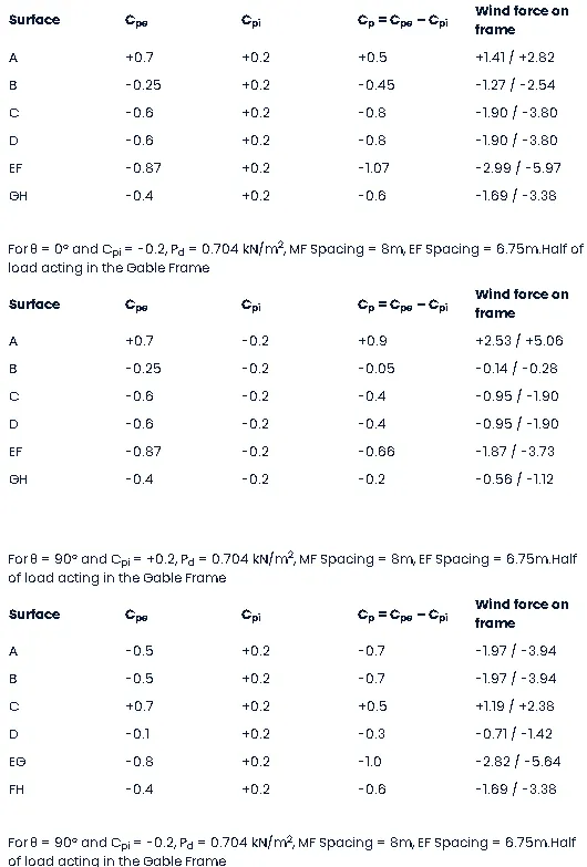
Step 6:
> Assign loads and create load combinations in STAAD Pro.
Step 7:
> Within the Analysis Tab, establish and assign parameters to the model.
Step 8:
> In the Design Tab, set up and assign design parameters to the model.
Step 9:
> Return to the Analysis Tab, click on "Run Analysis."
Output displays 0 errors.
Result:
* The proposed PEB building has been modeled and designed successfully using STAAD Pro.