Project 2
Aim : Using MATLAB or simulink and the drive cycle from the attached excel sheet we need to find the following
- The max heat generation of the battery
- The SOC of the battery at 2 *104second of the battery operation
1.The max heat generation of the battery
given data,
resistance = 0.5 ohms
entropic factor = 2
here we need to calculate the heat generation of the battery
formuela for
heat generation = joule heat + entropy heat
now we need to find joule heat for that purpose we use formuela
joule heat = I2R*T
Here we consider maximum current from the given excel sheet
P = (-1.008)2*0.5*0.8
=0.46
Now we use the above formuela
Joule heat + entropy heat
0.406 + 2 (Here we are taking entropy factor as 2)
=2.406
QUESTION 2:
2.The SOC of the battery at 2 *104second of the battery operation
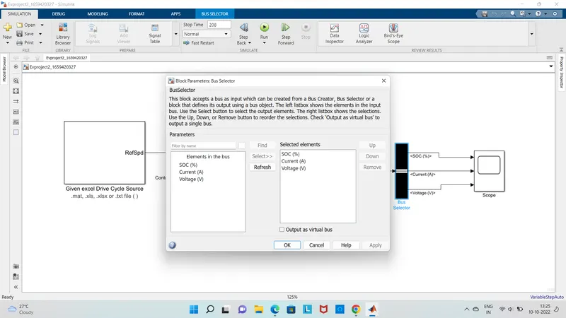
Simulink model:
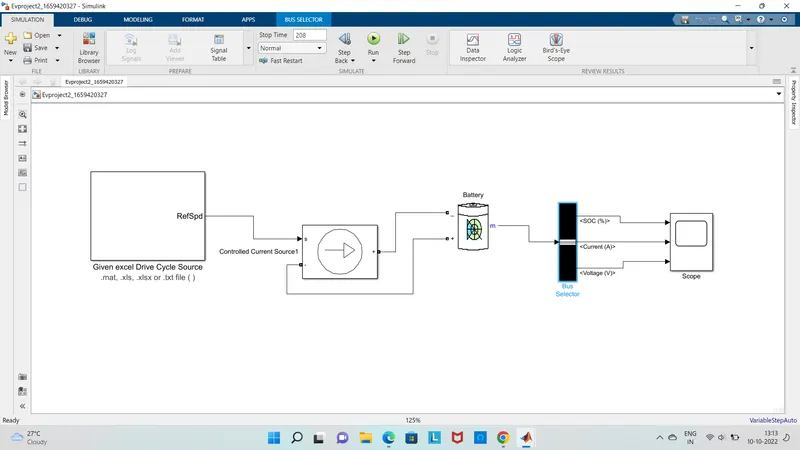
Blocks used:
1)Drive cycle
2)controlled current source
3)Battery
4)Bus selector
5)scope
DRIVE CYCLE:
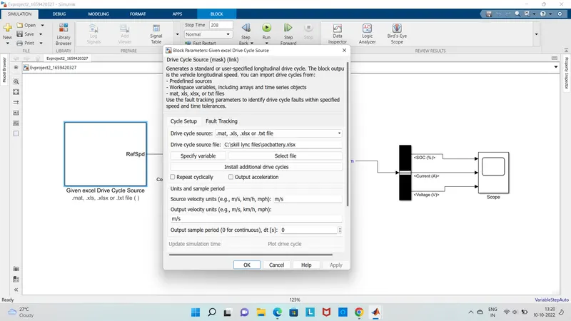
Generates a standard or user-specified longitudinal drive cycle. The block output is the vehicle longitudinal speed. You can import drive cycles from:
- Predefined sources
- Workspace variables, including arrays and time series objects
- mat, xls, xlsx, or txt files
Use the fault tracking parameters to identify drive cycle faults within specified speed and time tolerances.
CONTROLLED CURRENT SOURCE:
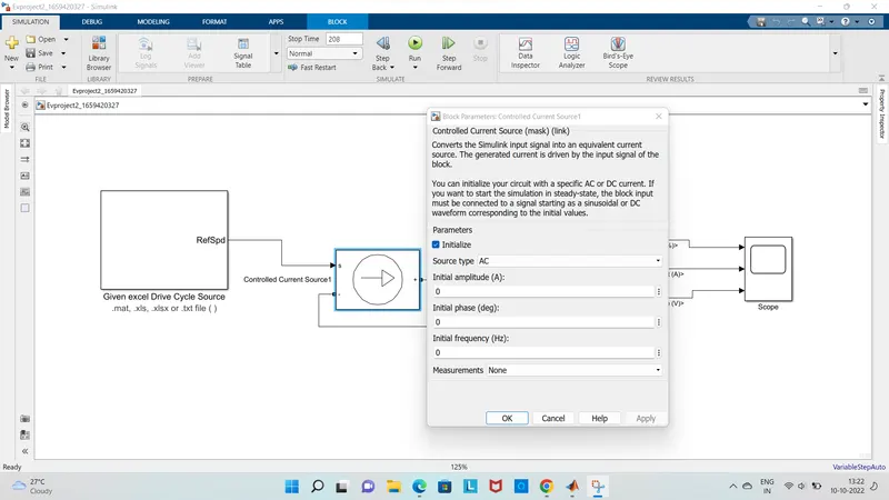
Converts the Simulink input signal into an equivalent current source. The generated current is driven by the input signal of the block.
You can initialize your circuit with a specific AC or DC current. If you want to start the simulation in steady-state, the block input must be connected to a signal starting as a sinusoidal or DC waveform corresponding to the initial values.
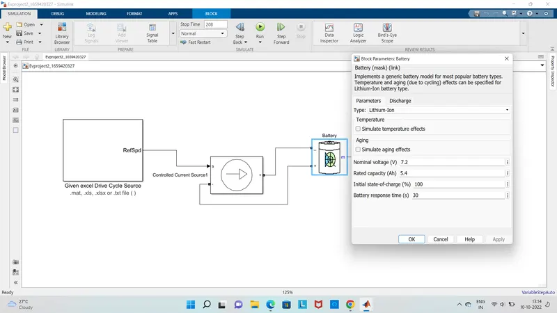
BATTERY:
Implements a generic battery model for most popular battery types. Temperature and aging (due to cycling) effects can be specified for Lithium-Ion battery type.
BUS SELECTOR:
This block accepts a bus as input which can be created from a Bus Creator, Bus Selector or a block that defines its output using a bus object. The left listbox shows the elements in the input bus. Use the Select button to select the output elements. The right listbox shows the selections. Use the Up, Down, or Remove button to reorder the selections. Check 'Output as virtual bus' to output a single bus.
Drive cycle input plot:
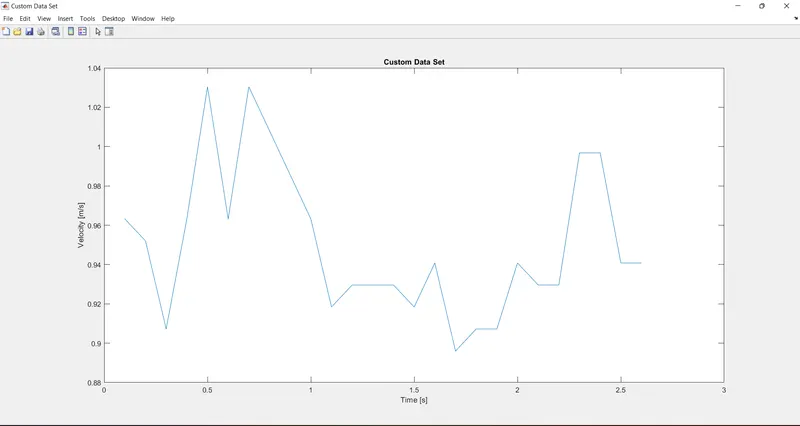
- This current cycle is given as the input to the model through the drive cycle input block i.e excel file wich is given in the question
- Here the drive cycle stop time is 2*104 i.e 208sec
- so the simulation run time is 208sec
- Here the output of the drive cycle is given to the current controlled source which is connected to the battery as a load
- so here the battery is dicharged accroding to this siginal given by the data which is excel data input drive cycle data
- Here the power gui block is rquired for any simulation of the simulink model
- It mainly used to store the equivalent simulink circuit which represents the state space model
- The ouput of a battery is given to the scope through the bus selector the bus selector outputs the battery siginals to the scope
Output results:
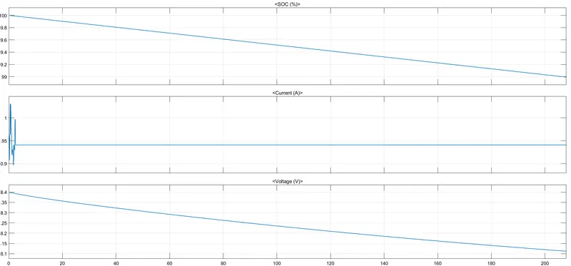
The above graph gives the results of SOC voltage and current
Here we operated the soc of battery at 2*104
And we can also see that how the soc of the battery changes it mainly decreases from the 100 to 99 and voltage aslo decreases