Mesh the Floor Panel Component with quality criteria using Hypermesh
AIM: To Create the mesh for the Floor Panel component with given quality criteria.
KEYWORDS: Aspect ratio, Skewness, Warping, Taper, Geometry cleanup, Midsurface, etc.,
SOFTWARE: Hyperworks
OBJECTIVE:
( i ). For the given component check for Geometry clean up & Topo the model.
( ii ). After the cleanup, perform the midsurface and again check for geometry clean up.
( iii ). After the midsurface, set the given quality criteria and perform the mesh operation by assigning the thickness.
INTRODUCTION:
HyperMesh is the market-leading, multi-disciplinary finite element pre-processor which manages the generation of the largest, most complex models, starting with the import of CAD geometry to exporting a ready-to-run solver file. HyperMesh supports a wide variety of CAD and solver interfaces, making it a perfect solution for most industry verticals and domains. With its advanced geometry and meshing capabilities, HyperMesh provides an environment for rapid model generation. Generating high-quality mesh quickly is just one of HyperMesh’s core competencies. For complex sub-system generation and assembly, HyperMesh has advanced model assembly tools. Modeling of laminate composites is supported by advanced creation, editing, and visualization tools. Design changes can be made easily via mesh morphing and geometry dimensioning.
( i ) GEOMETRY CLEAN-UP:
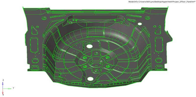
Direct readers to popular native CAD file formats. Robust tools to clean-up of complex CAD geometry. Automated thickness extraction and property assignment. Initially, the CAD model should import into the software and check for any geometry error found in the model. Here, in this model, there are a lot of missed surfaces that are cleared by creating the new surfaces by using a surface tool from geometry, and the toggle tool is used to remove the triple cons.
Before reading any CAD data into Hypermesh you can specify some settings concerning the application of Topology / Toggle (the connectivity of neighboring Faces), and the Resolution (the appearance of geometrical entities on the screen). These settings should correspond to the dimensions, level of detail, and tolerances of the CAD. Here, the CAD model as Side Door of a Car and the below figure shows that cleaned geometry by using geometry tool which is ready to proceed with Mid_surface.
( ii ) MID_SURFACE:
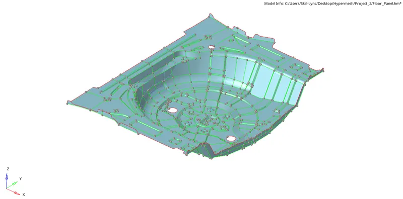
After completed the Geometry clean-up, the Model should proceed with Mid_Surface. In Mid-Surface, it can be done with Auto or Manual. In this casting model, the auto mid-surface is not working due to some complex features and irregular thickness present in the model so Midsurface obtained manually selecting the outer surface of the component and did offset or by creating the partition in the model and create midsurface part by part. Some features and ribs are taken by using the surface pair option. The Mid-Surface of this model is shown below,
( iii ) MESHING:
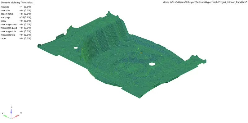
After completed the Mid-surface with zero geometry error, the model is ready to mesh as per the quality criteria. Manual, semi-, and fully-automated mesh generation tools, including batch meshing to ensure the highest quality model discretization. Manual type meshes as selected with mixed element i.e., both trias and quads. Before begin with meshing, we need to assign Quality criteria & mesh parameters.
RESULTS:
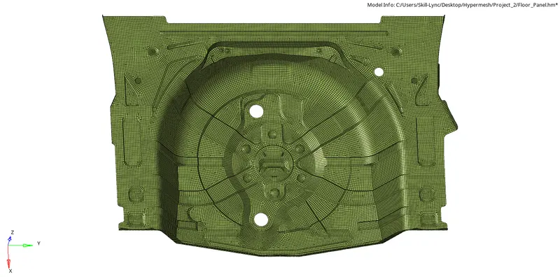
Mesh with Assigned Thickness:
CONCLUSION:
- In this model, completed the geometry clean up, topo and midsurface. After all the processes started applying the mesh as per the quality criteria.
- The midsurface can be created manually, the auto midsurface was not working for this model.
- After all the midsurface created, started doing mesh for all parts. The mesh used is a mixed type.
- After completed all the mesh assigns thickness as per the original geometry.