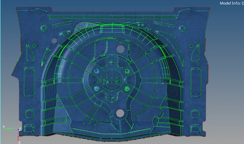
PREPROCRESSING ON A FLOOR PANEL COMPONENT BY USING HYPERMESH
AIM :
To Performing a preprocessing operation on a given floor panel component by using Hypermesh software.
OBJECTIVES :
1) Geometry Cleanuping on a given parent component.
2) Generating the manual middle surface from the parent component.
3) Geometry Cleanuping on a extracted middle surface.
4) Meshing on a extracted middle surface as per given element quality Criteria.
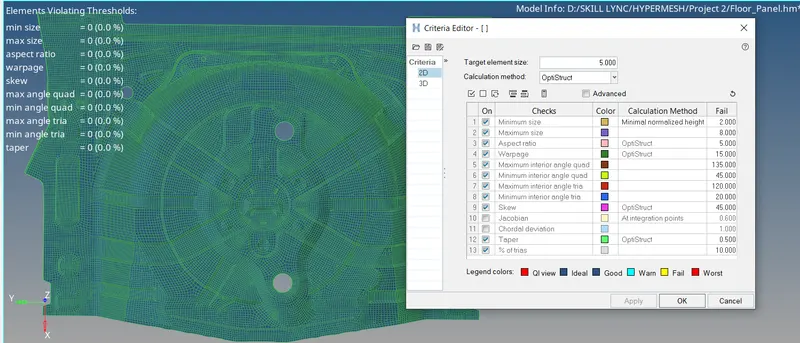
5) Checking the element qualities with compared into given quality parameters.
6) Assigning a property and material card to the model.
CAD MODEL :
Open a Hyperworks Software, set the User Profile which is "Optistruct" it means Optimization enabled structural Analysis. Click the "Import Solver Deck" Option for which importing the approriate file, followingly choose the "Import Model" option because given model has (hm) file and then followingly choose the appropriate file which we gonna perform preprocessing operation.
After importing the model, by default hypermesh set into "Auto" mode from where "Geometry Color mode" GUI option with default white color. It will looks like as shown in the below image.
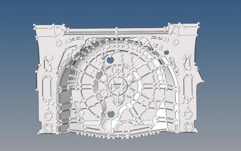
Inorder to view the topology edges, we have to manually change into "By Topo" mode instead of "Auto" mode.
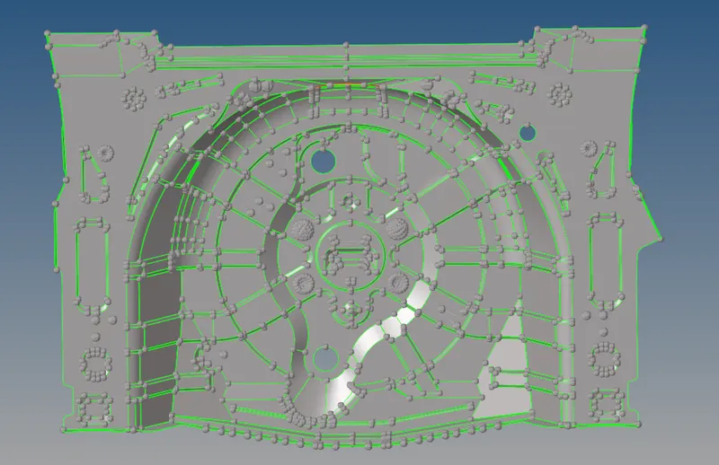
After changed into "By Topo" we are able to see the topological edges such as Free, Sharped, Supressed and then Non Manifold.
We have to carefully notice, some parts are extractly symmetrically about X axis.
i) Organizing into single component :
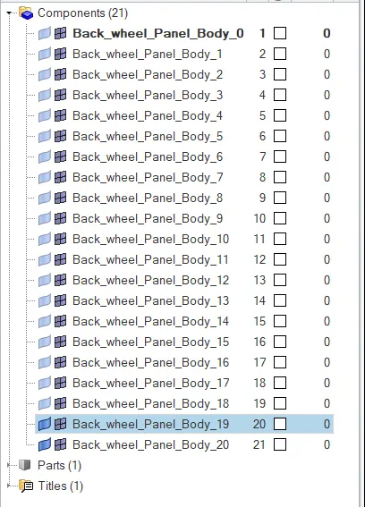
We have 21 components are available, some necessary surfaces are saved in different components. We have manually organized those surfaces into single component.
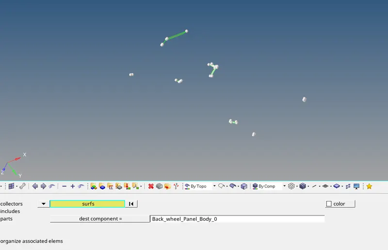
Inorder to organize it, we gonna "Organize" panel under the "Tools" main menu option. Set the current component by using "Destination Component" option or else "Right Click on the mouse button and click the Make Current" option. In this case, current component which is shown as above image.
Select the chunk of important surfaces & point which are showing in the below image and then click to organize the surface & points into the current component.
After organizing, delete the unwanted component except current component.
PROCEDURE FOR ACQUIRING THE OBJECTIVES :
i) Geometry Cleanup On a Parent component :
In the given component, there's some surface are overlapped eachother like as shown in the below first image. We have manually recorrect it by using option which are Filler, Ruler, Toggle, Delete and then Split Surf line & Node as well.
After Recorrect the errors, by result gets properly surface on that particular area. It will looks like as shown in the below second image.
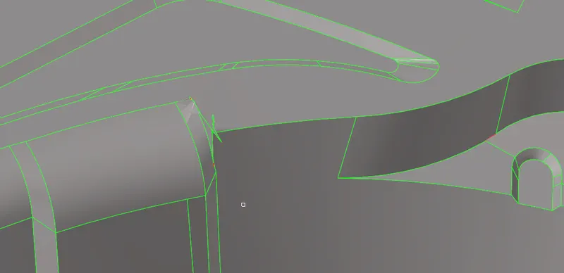
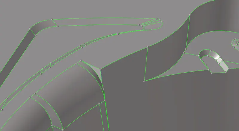
This is a error, it showing combination of free edge & Non manifold edge. But, we have only sharped edge on that particular area as shown in the below first image. Because, feature edge is not connected more than two surfaces.
So, we have use some tools for which rectifying those error like toggle option with appropriate tolerance and then Replace point tool as well.
Make sure, we have change to "Wireframe" mode instead of "Shaded Geometry and Surface Edge" mode for better visulaization topological edges in both front and back.
Make sure checking by using wireframe mode, If the top surface is not attaching to bottom surfaces. If it happens, some peculiar issues are created on a middle surface.
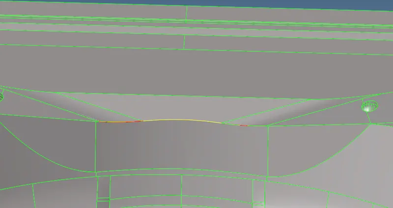
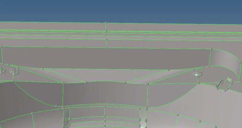
In this given model, some more few feature edges are not proper apart from which is shown in previous. Inorder to rectifying that issue, similarly we have manually performing on it.
ii) Generating the middle surface :
First of all, We have to measure the cross section thickness by using "Two Points" option under which "Distance" panel. Inorder to measure the distance, we gonna select "Distance" panel under which "Geometry" main menu panel Or else directly press the "F4" button from the keyboard. Select the "Two points" option and select the appropriate points, hypermesh will showing the results automatically. A component thickness is 0.75 mm throughout the entire component.
As we know, a middle surface is generating between the two surface at exactly center. Inorder to create the mid surface, we gonna select the "Surface Edit" panel under the "Geometry" main menu option. Followingly select the offset option, keep the offset distance which is half a parent thickness distance.
Select the top surface like as shown in the below image, followingly duplicate the selected surface to the current component.
Make sure check the vector direction before gonna extract the mid surface. Finally, click the offset option to which create a middle surface in properly.
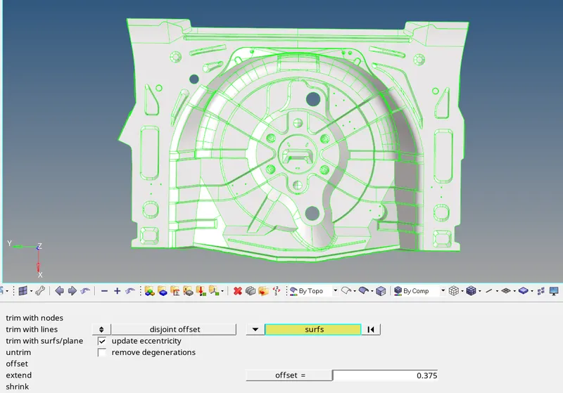
After creating the middle surface, it will looks like as shown in the below image.
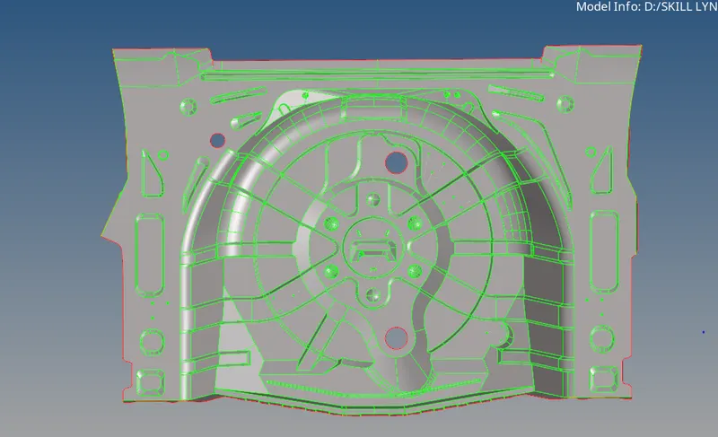
iii) Geometry Cleanuping on a middle Surface :
We have to supress those excess lines due to affect the mesh element flow & element quality as well which are presented as shown in the below first image. By using "Toggle" option under the "Quick Edit" panel to supress the excess line. After supressing some lines, it will looks like as shown in the below second image.
Similarly, we have to do same procedure on those areas are presented like as shown in the below image
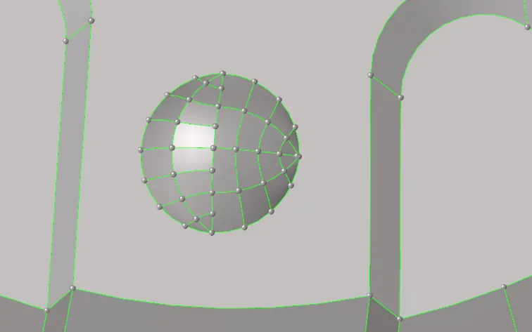
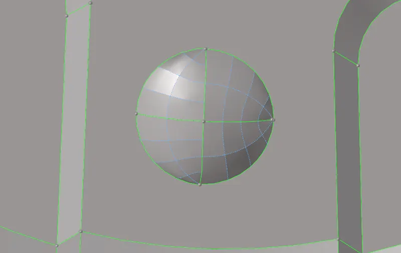
We have remove those pin holes due to affect the element quality and mesh flow. First of all, delete the pin hole surface by using "Delete" Option, followingly fill the hole by using "Filler" Option and then supressing those lines by using "Toggle" option. After done this, it will looks like as shown in the below second image.
Similarly, we have to do same procedure for removing the pin holes which are presented in the entire component.
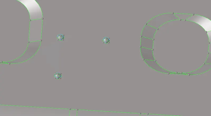
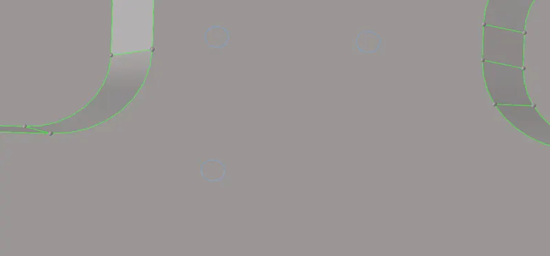
iv) Meshing on a middle surface :
Generally, To discritization of a entire component into infintesimal control volume, that frame work is called meshing. This process is called discritization.
As we notice, some surfaces are exactly symmetrical in shape about an X axis. So, we perform meshing operation on one side and then easily reflecting the elements on another side by using "Reflect" Option.
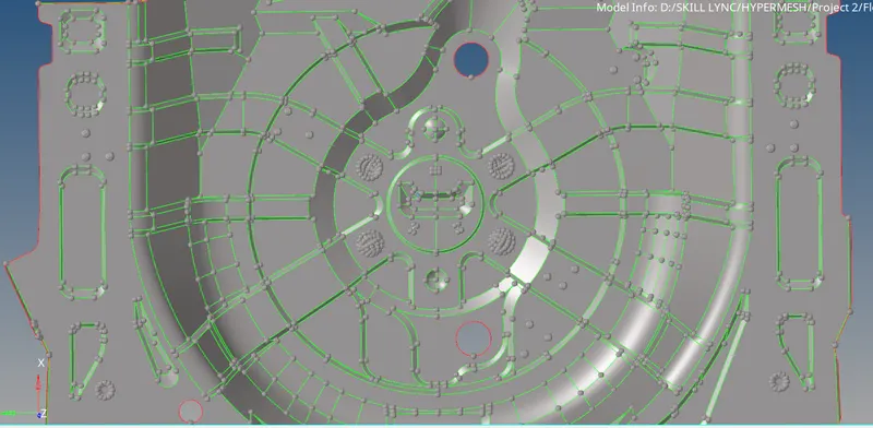
Select the "Auto Mesh" option and set the selection type which is "Surface". Select the any one of the surface and click to mesh.
A Given target element length is 5mm and element type which is "Mixed". If we use "Quad" element type, it will made with some few rotational quad elements are involved . So, we mostly "Mixed" element type is perferred.
Inorder to capturing the proper mesh flow, we have to starts the meshing operation on where center of the component. If generated mesh elements should not be proper flow, we have to remeshing again and again untill we get capture proper mesh flow on it.
Some Surfaces are symmetrically in shape about an X axis. First of all, meshing the half a portion which comes under the symmetrical in shape and then reflecting the meshed elements on a another portion.
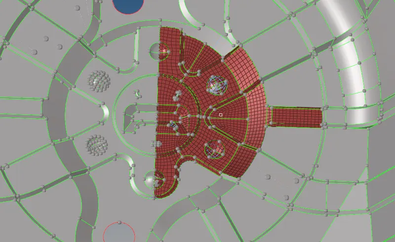
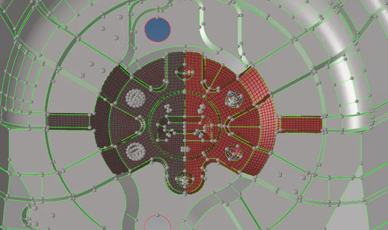
Go to "Tools" option, followingly select the "Reflect" option. Select the elements for which reflecting on another side and then creating the duplicate elements.
Make sure set the appropriate current component before creating the duplication of elements. After click the reflect option, it will looks like as shown in the below image.
Make equivalence with nodes between the two elements by using "Equivalence" option under which "Edges" panel. If elements are missed the connectivity.
Remaining parts are not exactly symmetrically in shape. So,we manually generate the elements on a each and every surface as per given element criterias.
Inorder to perform meshing operation, we should concerned about meshing conditions which are "Low trias concentration", "Proper mesh flow with same element type", "Remove Opposite trias", " Avoid trias are failing along the feature line", "Proper feature capture" and then "connectivity between the elements".
After completion of meshing operation, a model will looks like as shown in the below image.
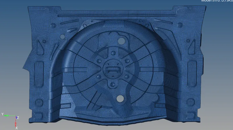
v) Checking the element Qualities :
A Generated mesh elements are satisfied in all given element parameters.
vi) Assigning a Thickness :
First of all, we have to create a new property card and material card as well. As we know, parent component cross section thickness is 0.75 mm.
Assume material card name is steel, provide the thickness value into the property card.
Select the appropriate component and right click on it, followingly choose the assign option to which assigning the appropriate material and property card.
Inorder to view the assigned thickness from the elements, we have to change into "2D Detailed element representation" instead of "2D Traditional element representation".
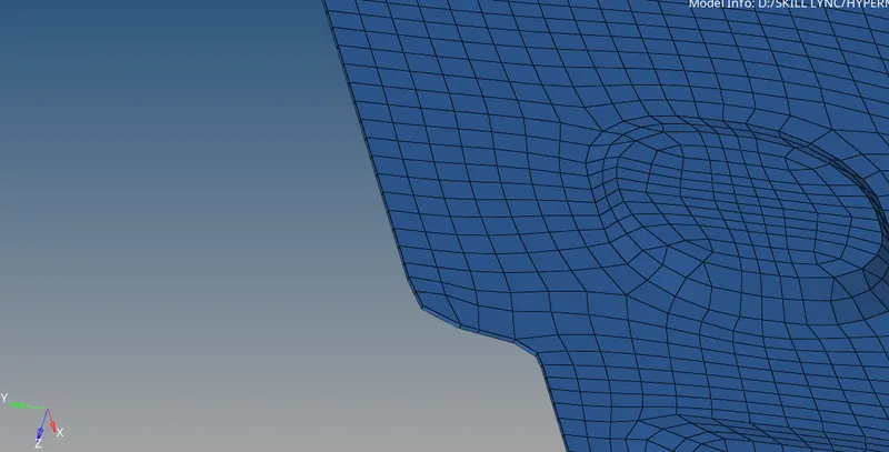
After assigning the thickness, it will looks like as shown in the below image.
CONCLUSION :
Successfully completion of preprocessing operation on a given Floor panel component like geometry cleanup on a parent component, Extracting the middle surface from parent component, Meshing on a middle surface as per given element criteria, Quality checking and then assigning the thickness as per given parent component thickness.