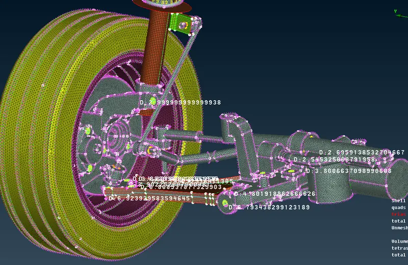
Project - FE representation of the Front suspension Sub Assembly of the Car Using ANSA
Project 2 - FE representation of the front suspension of the Car.
Aim - Perform Tetra Mesh and Shell mesh to various parts of the suspension according to the given quality criteria.
Briefing
The job of a car suspension is to maximize the friction between the tires and the road surface, to provide steering stability with good handling, and to ensure the comfort of the passengers.
The suspension of a car is actually part of the chassis, which comprises all of the important systems located beneath the car's body. These systems include:
- The frame - structural, load-carrying component that supports the car's engine and body, which are in turn supported by the suspension
- The suspension system - a setup that supports weight, absorbs and dampens shock, and helps maintain tire contact
- The steering system - a mechanism that enables the driver to guide and direct the vehicle
- The tires and wheels - components that make vehicle motion possible by way of grip and/or friction with the road.
The mid surfacing is generated for surfaces with less than 5mm and Volume Tetra mesh is performed for the other parts.
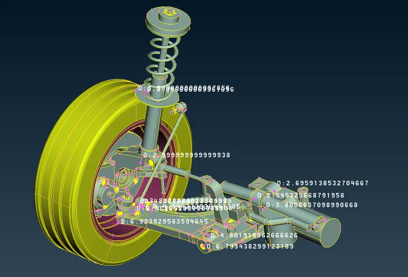
Procedure
- Perform Topo clean up of the geometry and make sure that parts have closed volumes for tetra mesh
Tyre and Rim - Tetra meshing is to be performed on these parts
Quality Criteria for Tria Elements (Tyre and Rim):
|
S.No |
Quality Criteria |
Value |
|
1 |
Target/Average length |
6.5 |
|
2 |
Minimum Length |
5 |
|
3 |
Maximum Length |
10 |
|
4 |
Skewness |
45 |
- Initially, the tria shell mesh is performed before the volume meshing.
- Batch meshing - scenario is created for these two parts and mesh parameters are inputted into the scenario.
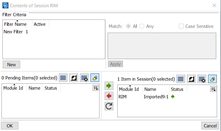
- Quality of the trias are fixed before volume meshing using split and move tools.
- Next, the volume is created and then tetra meshing performed.
- Once the volume meshed, Tet-collapse 0.2 is satisfied, kinks and dinks are fixed.
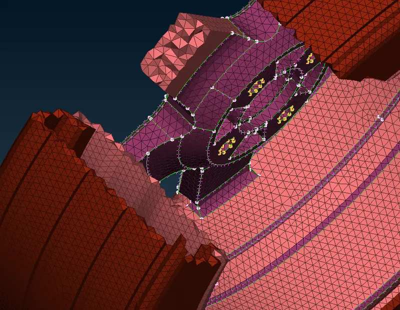
Mid surfacing of parts that have less than 5mm thickness
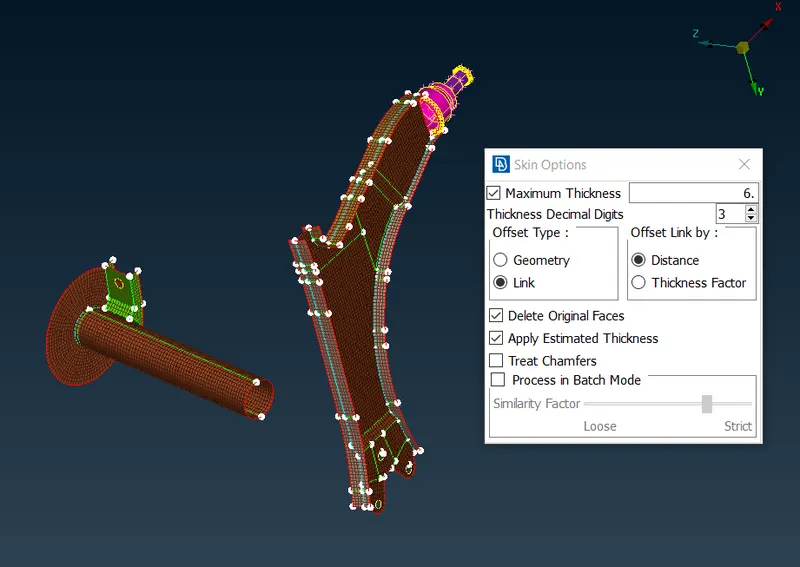
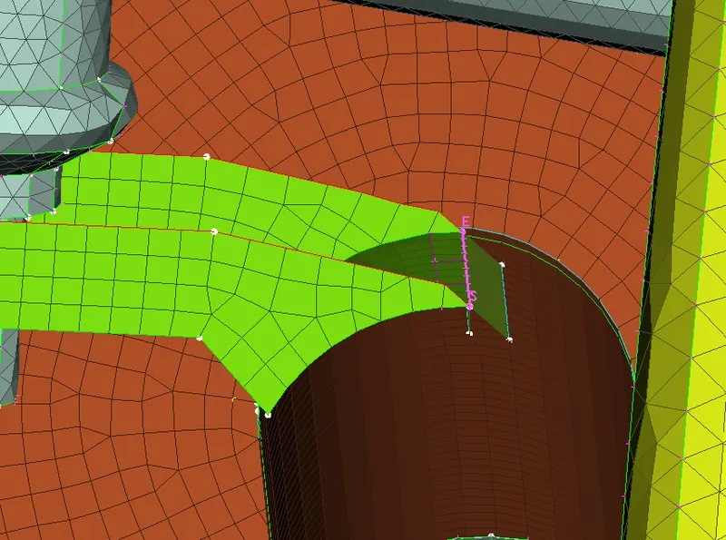
- Skinning is used to generate the mid surfaces and set PID is used to organize the macros according to their respective thickness.
- Best and spot mesh is used to perform the shell meshing of these components.
|
S.No |
Quality Criteria |
Value |
|
1 |
Target/Average length |
4 |
|
2 |
Minimum Length |
2 |
|
3 |
Maximum Length |
6 |
|
4 |
Aspect |
3 |
|
5 |
Warpage |
15 |
|
6 |
Skewness |
45 |
|
7 |
Jacobian |
0.7 |
|
8 |
Minimum Quad Angle |
45 |
|
9 |
Maximum Quad Angle |
135 |
|
10 |
Minimum Tria Angle |
30 |
|
11 |
Maximum Tria Angle |
120 |
- Again the quality of the shell is fixed and unwanted trias removed.
For other components tetra meshing
|
S.No |
Quality Criteria |
Value |
|
1 |
Target/Average length |
4 |
|
2 |
Minimum Length |
2 |
|
3 |
Maximum Length |
6 |
|
4 |
Skewness |
45 |
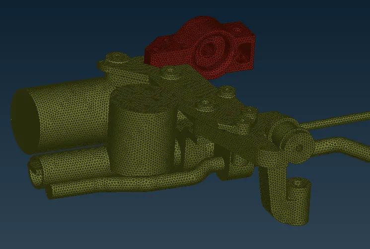
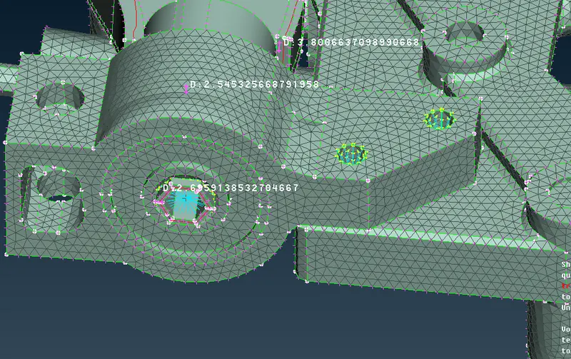
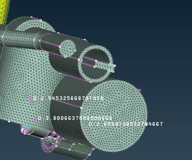
- Each part is batch meshed with trias, the volumes are created for individual parts before tetra meshing.
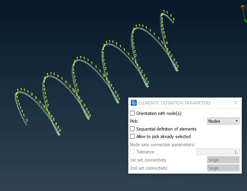
- Spring is represented using 1D bar elements with element length 3.
Connections
- Spot weld, bolt connections are used to connect the various parts of the subsystem.
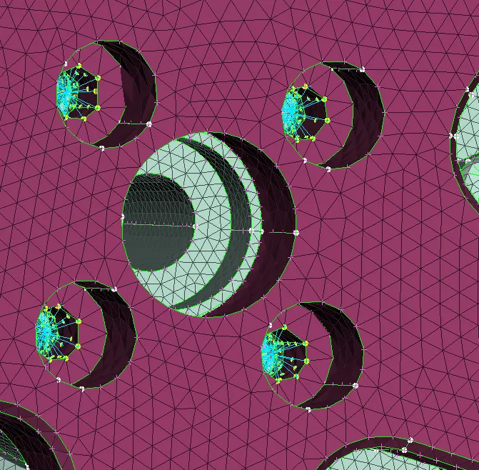
- The Rim, hub, disc, and knuckle are connected to each other using bolt FE representation using RBE2 elements
- The brackets are seam welded to the strut using overlap shell weld.
- Other Volume Tetra meshed components are again joined together using cluster RBE2 and then joined together using a two-node RBE2.
Learning Outcomes :
- Solid Tetra meshing and Preparation for volume meshing using trias.
- Understanding of connections between the various parts of the Suspension subsystem.
Conclusion :
- The subsystem is represented as the FE model by making sure the input mesh parameters and quality are met.
- Drive Link : https://drive.google.com/file/d/1d9XctaFBeDtBhaYajqDq6tk3tlPkpa7A/view?usp=sharing