OBJECTIVE:
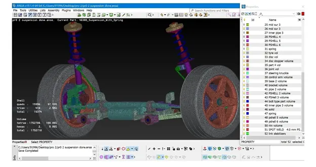
Importing rear car suspension geometry into ANSA.
Clean up the geometry until no topological error is found.
Generate mid surface for required parts.
Generate volume mesh for hollow parts.
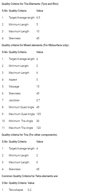
Improve the mesh flow and solve off elements according to given quality criteria.
Give connections for rear suspension for NVH analysis.
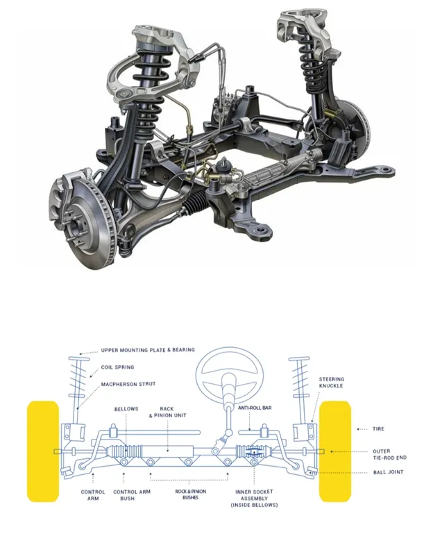
Suspension has been an essential component of automobiles. The rear suspension of a vehicle performs the same general function as front suspension, but the specific construction is typically quite different.
The ideal suspension for a vehicle depends a lot on the vehicle's body style and performance requirements.
The most basic purposes of a suspension system are to prevent the body of a vehicle from hitting the ground and to keep the tires in contact with the road.
Qualtiy Criteria:
PROCEDURE:
Import the geometry into ANSA and do topo to stitch the surfaces. Isolate each part and set PID’s for the rear suspension geometry.
Clean the geometry using checks manager. Enable unchecked faces, collapsed cons, triple cons, needle faces, overlapped faces, cracks, single cons. Clear all these issues until no error is found. One can use fix option in ANSA to clear all the errors automatically. However, sometimes manual intervention is required for fixing some errors. Manually we can use options like cut, release and delete for topo clean up.
Surface Mesh Generation for Tyre and Rim
One can do mesh generation for tyre and rim either by meshing them manually using spot mesh or by batch mesh.
The advantage of batch mesh is that ANSA will do topological clean up automatically which is a time saving process. Even though sometimes we must clear some errors manually after batch meshing also.
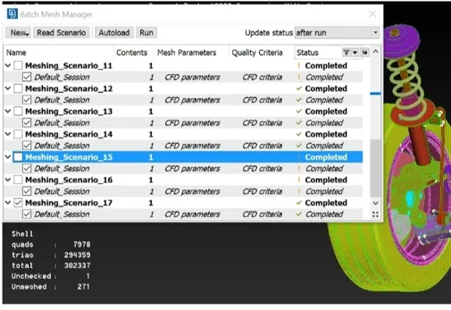
Mesh generation using Batch mesh option. The 1st step is to create a new part in the model browser and assign the mid surface to that new part. Then open the batch mesh and create a new meshing scenario.
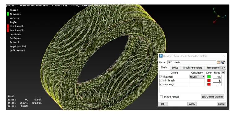
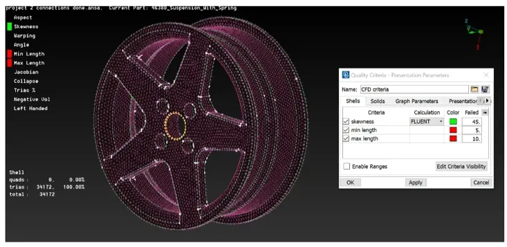
Volume Mesh Generation for Tyre and Rim
After clearing all the off elements on the surface mesh one can proceed further to volume mesh generation.
Volume mesh can be created in ANSA only if it recognizes the geometry as a closed volume. Therefore, we must manually update our model to closed volume.
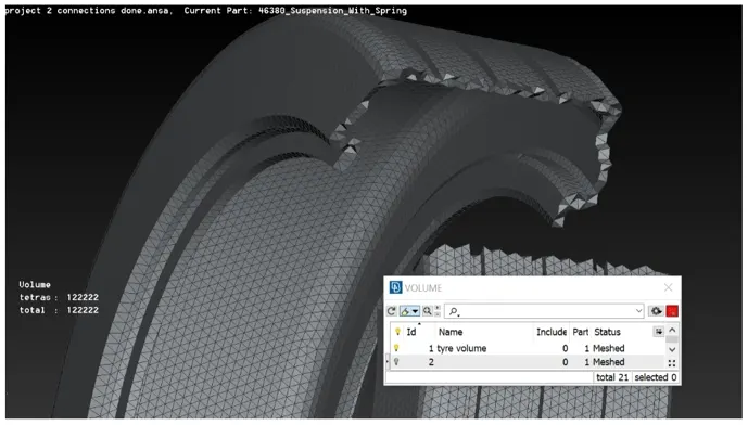
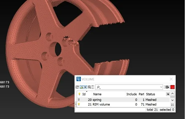
To convert our model to closed volume one must define volume.
ANSA might crash if you generate volume mesh for the whole geometry. So, define individual closed volumes for different PID’s.
Defined volumes can be checked under list option under volume dialog box.
One can give either Tetra Rapid or Tetra FEM under unstructured mesh dialog box for closed volume.
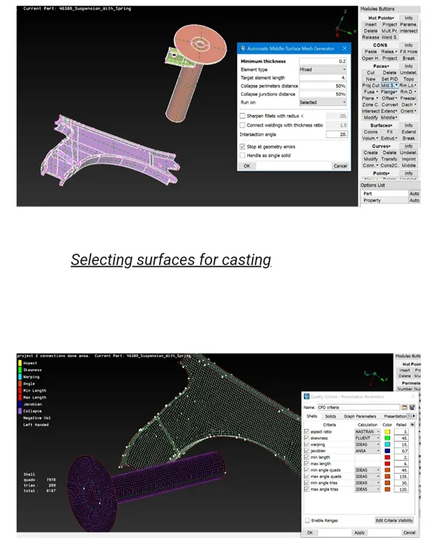
Mid Surface Generation for sub frame and macpherson strut outer surface
Using Casting option:
Surface mesh generation and volume mesh generation for remaining parts
For Remaining all parts, I have generated batch mesh by isolating each part individually.
After generating batch mesh clear off elements manually.
Trias or ortho-trias are used as surface mesh for volume generated parts.
After surface meshing, define closed volume individually for each part in Nastran deck. After thAT a list of volumes comes and Tetra rapid is used.
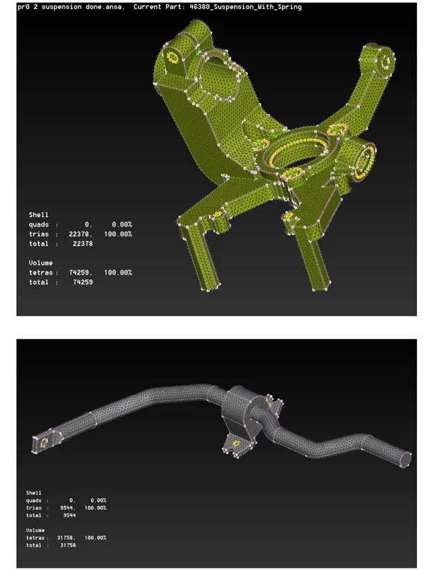
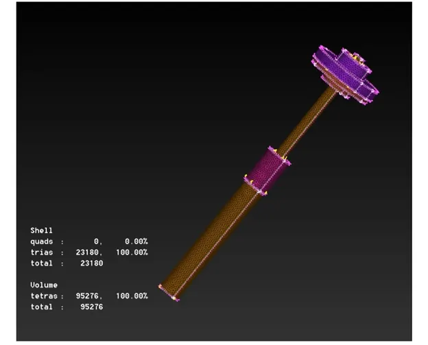
Connections for rear suspension
After completion of mid surface and volume mesh we must connect them by using connections like bolt connection, spot weld connection, seam weld connection etc.
Bolt connection can be generated using RB2 option in the Nastran deck.
Cluster or Spider RB2: This connection is used when a manual bolt connection must be deployed between two or more surfaces.
For automatic bolt connection one must follow these steps, Create COG for the hole à COG is basically a 3D point, convert this 3D point to bolt à Now open connections manager and select the bolt symbol which has created in earlier step à Then assign P1,P2,P3 à Select FE type as Bolt and give the required values and constraints à apply and then realize the connection.
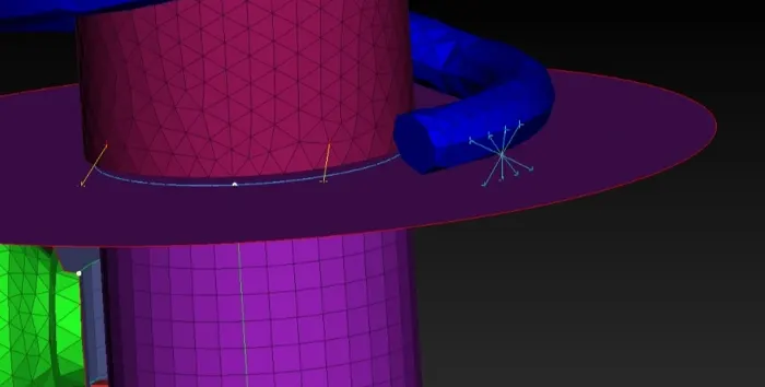
Spot weld is generally a solid connection deployed between 2 surfaces.
For generating spot weld connection first create a COG point on the FE.
Now, convert this 3D COG point into spot weld using convert option.
Then select the generated spot weld point using connections manager. In the connection’s manager assign P1 and P2 for 2 mid surfaces which are to be connected using spot weld.
Create COG à Convert COG to spot welding point à Use connections manager to generate RBE3-HEXA-RBE3.
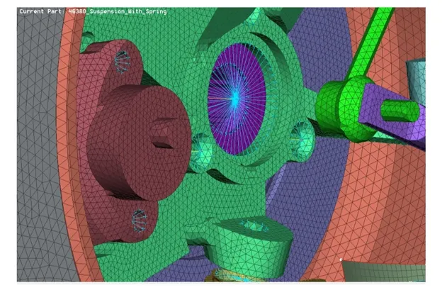
Connections for whole assembly of rear susp
Transform
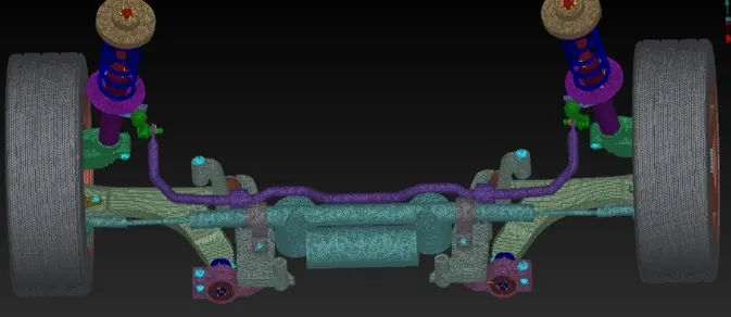
After completing surface mesh, volume mesh, mid surfacing and connections we have to use transform option in order to create exact mirror of the model on the other side.
Use transform and select all the entities including connections to generate exact replica of the model on the other side.using symmetry à mirror 3 points plane option and select 3 points on the edge. These 3 points represent all the 3 coordinates (x, y, z). This helps all the entities to transform on the other side.
Link: https://drive.google.com/file/d/1lpikeSZ1pYxqaZkEBoaBYzdkDC2lOEl1/view?usp=sharing