Project 2 - 2D meshing on the instrumental Panel
AIM :
The FE-model has to be generated from the given Automotive Instrumental panel semi-trimmed component within the given element's Quality criteria and assign thickness by using the ANSA preprocessor tool.
OBJECTIVE :
- Import and clean up geometry on the given Instrumental panel semi-trimmed component using ANSA GUI.
- Extract the mid-surface with suitable mid-surfacing techniques.
- Mesh the generated mid-surface and reconstruct the mesh to satisfy the following quality criteria.
- Complete the PID and thickness assignment of the model.
SOFTWARE TOOL USED :
ANSA Version 22.1.0
( NOTE : In this Project, there will be some off elements found in the chamfer region which cant be removed. It is acceptable as it is been found due to the presence of triple cons on the chamfered surface. Due to those triple cons, there will be some quality criteria failures that can be acceptable and those quality fails can be neglected. )
GIVEN DATA :
- CAD model.
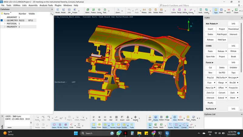
2. Quality criteria.
|
S.No |
Quality Criteria |
Value |
|
1 |
Target/Average length |
4 |
|
2 |
Minimum Length |
2 |
|
3 |
Maximum Length |
6 |
|
4 |
Aspect |
3 |
|
5 |
Warpage |
15 |
|
6 |
Skewness |
45 |
|
7 |
Jacobian |
0.7 |
|
8 |
Minimum Quad Angle |
45 |
|
9 |
Maximum Quad Angle |
135 |
|
10 |
Minimum Tria Angle |
30 |
|
11 |
Maximum Tria Angle |
120 |
|
10 |
Tria Percentage |
15 |
THEORY :
1. Instrumental Panel :
The Instrument Panel (IP, dashboard, or fascia) is the portion of the dashboard that sits behind the steering wheel. It houses various gauges and lights which update the driver on the vehicle's status. As a driver, one should always pay attention to it to avoid dangerous situations. It provides drivers with a centralized and easy-to-view display with all key driving information of the vehicle. It is the driver’s workplace; an ideal cluster dashboard that can be securely updated and offers flexible customization if required.
The instrument panel warns you about traction control issues, low or high engine temperature, fuel reserves, and much more. It helps to react appropriately to any issues that arise, giving drivers ample time to address them.
The following are the most common elements that are on the Instrumental panel;
- Speedometer
- Tachometer
- Odometer
- Fuel gauge
- Temperature gauge
- Turn signal indicators
- Gear display
- Warning lights
- Coolant level
- Battery status
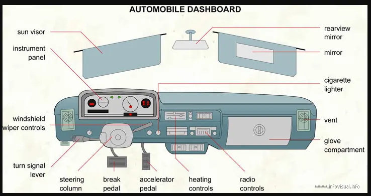
2. Quality Criteria :
Every product which is been produced will go through a set of quality checks. If the quality check fails other steps like boundary condition & applying loads will not be feasible, So for this reason the element quality check is performed. To identify the quality failure the quality criteria will be entered as input data. The elements should be maintained within the given quality criteria values. If the given quality value is not maintained there will be a failure in quality.
3. Geometry Clean-up :
Importing the model from other software to ANSA results in some geometrical deviations which need to be cleared before proceeding to other steps. In General chamfer/fillet faces, Unchecked faces, and average length errors occurred which is common while importing the model to ANSA from Modelling software. These errors must be cleared before any further operations. This clean-up will give the proper finish to the component and allow the engineer to work further with ease and accuracy.
4. Topological Activity :
Topology describes how the different faces and features of the geometry get connected with each other by forming CONS. There are 3 types of CONS which are SINGLE CON (Red), DOUBLE CON (yellow), and TRIPLE CON (Cyan Blue). Before mid-surfacing the entire model must be of double cons, the rest all the single and triple cons must be removed for getting better results while doing analysis.
Boundary Cons of the faces and Features were called feature lines other Cons in the Model were called Construction Lines which were generated during the modeling of the component. Construction lines can be altered if one wants to get a better mesh flow. Feature lines should not be disturbed as it will result in a change in geometry however if the cons Length is less than the minimum element size it will result in element failure under such circumstances the feature line can be altered up to some extent without giving up the design feature of the part.
5. Orientation :
Orientation in ANSA is indicated by Grey or Yellow surfaces Grey surface usually acts as a positive direction and Yellow acts as a negative direction. The face is said to be inconsistent if one face has both Grey and Yellow Colours. The faces Orient option will fix this issue by changing one side of the face to be yellow in color and the other side to be Grey in color this will make the model consistent.
6. Mid-surface creation :
Mid-surface is the exact middle layer or surface of the component having uniform thickness over the part. Midsurface is used to do the meshing which will make the operation easy to inspect the errors and perform all the other operations.
Here the component is a Floor Panel (Sheet Metal) as the thickness of every face is the same (if the thickness of the component is different at multiple faces, the component is Plastic)
Mid-surface can be done with two approaches i.e. The Manual Approach and The Automatic Approach.
The manual approach includes the Faces offset method. In the Faces offset method, the engineer measures the thickness of the component at various faces and gives offset as thickness divided by 2, this will generate the exact mid-surface of the component. The offset method is carried out mostly on the sheet metal component as the thickness is the same on all the faces.
Faces Offset Approach :
Topo module -----> Faces -----> Offset -----> Selecting the faces and the offset value.
The Automatic approach includes the Faces mid-surface method. In the Faces mid-surface method, there are two methods i.e. skin method and the casting method. In the skin method, ANSA will automatically identify the upper surface, a lower surface, and thickness and show them in red, green, and blue colors, and in the casting method, a dialogue box appears. by inserting the basic values i.e. minimum thickness & target average length the mid surface and meshing both are done in one go.
Midsurface Skin Approach :
Topo module -----> Faces -----> Midsurface -----> Skin -----> Select the whole component -----> Dialogue box will appear (do correction if needed) ANSA will automatically identify the upper surface, lower surface & thickness and color them into green, red, and blue -----> middle mouse click.
Midsurface Casting Approach :
Topo module -----> Faces -----> Midsurface -----> Casting -----> Dialogue box will appear (Automatic Middle-Mesh Generator ) -----> Insert the Minimum thickness as 1 and target element length as 3 -----> Click Ok.
7. Meshing/Mesh generation :
Mesh generation is the process of discretizing the entire model into smaller elements.
2D mesh has three types of elements:
- Quadrilateral or Quad Elements
- Triangular or tria Elements
- Rotating Quadrilateral Elements
Quadrilateral Elements:
Quad elements were the elements having four nodes. The square is considered to be an ideal quad element and the deviations were calculated in comparison with the square element. Quad elements were structured elements. They have short processing time and also have higher accuracy. Therefore, Quad elements were preferred over the tria elements.
Triangular Elements:
Tria elements consist of three nodes. Equilateral Triangle is the Ideal tria element and deviations were compared with the Equilateral Tria Element. Tria element is said to be unstructured mesh. The stiffness of the Tria element is high which results in higher processing time and also has low accurate results. Therefore, every engineer should try to avoid the maximum possible number of triangular elements.
Rotating Quadrilateral Elements:
Rotating quad elements were formed when any one corner of the 5 quad elements meet at a point to form a Star like structure. Even though they were quad elements they should be avoided in the model as they act like the tria elements.
8. Meshing flow and quality improvement :
In ANSA mesh can be generated easily but the mesh will have a lot of elements generated such that they fail to fulfill the Mesh Quality criteria also the mesh will have Triangular elements which need to be eliminated. Mesh Flow and Mesh quality improvement are the most important steps in order to achieve good mesh quality and good Mesh Flow. To improve the mesh Quality there are many options available in ANSA, some of them are :
- Reconstruct
- Smooth
- Split, Swap
- Macro Join, Elements Join
- Hot points Delete, Faces Delete
- Changing Nodal numbers (Num+/-)
- Edge2Perimeter
Mesh is generated and the Mesh quality and the Mesh flow are improved using the above-said options for the entire model.
9. Why the Meshing must be carried on the Mid surface ?
Element thickness specified by the user is assigned half on the top and half on the bottom side. Hence in order to represent the geometry, it is necessary to extract the mid-surface and then mesh.
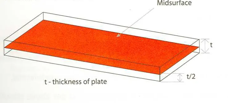
All sheet metal parts, plastic components like instruments panel, etc. In general 2-d mesh is used for a part having a width/thickness ratio>20.
PROCEDURE :
Step 01 : Importing CAD Model.
- The initial step is to import the geometry into ANSA Software.
File -----> Open -----> Select the file -----> Open (Or we can drag and drop the file into ANSA)
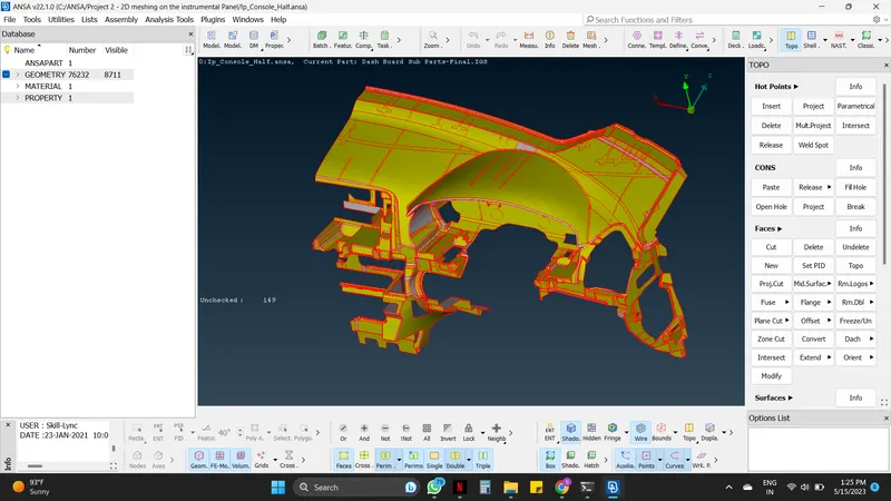
Step 02 : Geometry cleanup
- The resolution of the cons must be done to check the actual shape of the cones in the geometry. There are two tools for that. One is the 'Fine' option in the Topo module under Auxiliaries. The other one is the 'Length' tool from the Mesh module under Perimeters. The 'Length' tool will help to do this in a single step when compared with the fine tool.
Mesh module -----> Perimeters -----> Length -----> Perimeter/macros (do this for both) -----> Select the whole surface -----> Middle mouse click -----> Give the value as 1
-----> Apply.
- After the resolution of the con, the TOPO operation is carried out to convert all single cons into double cons.
Topo module -----> Faces -----> Topo -----> Select the whole surface -----> Middle mouse click.
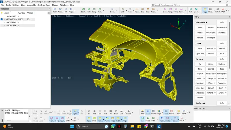
- It is observed that the given surface is with mixed yellow and grey color. This shows a mixed normal direction on the surface. So, to correct it as either yellow or grey on the outer surfaces to either gray(+ve) or yellow(-ve), preferably gray the tool, 'Orient' is used for this purpose.
Topo module -----> Faces -----> Orient -----> Choose select, Visible, and Auto appropriately.
If cons correction is done properly, choosing the visible option will change the color of entire surfaces in one go.
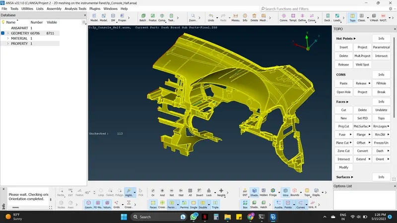
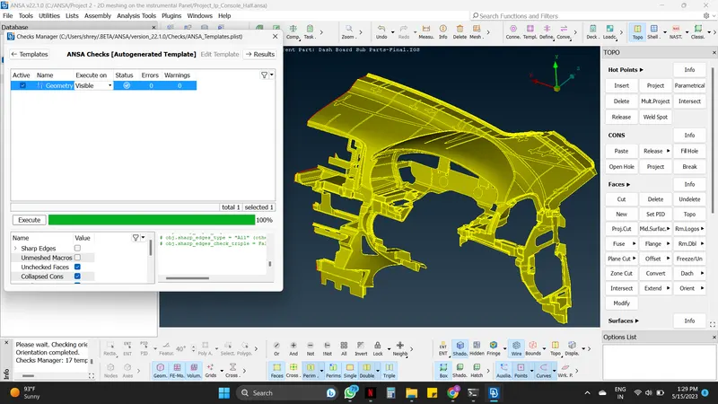
- After all the above operations the last step for the cleanup will be checking any geometrical errors and cleaning it.
Tool tab -----> Check -----> Geometry -----> Execute -----> If any errors pop up in red color select them at once -----> Right mouse click -----> Fix -----> If not fixed, try manually -----> Then execute the geometry check again, it will show No errors or warning exist.
- Here in this sheet metal component, there were some errors. Using the fix option some errors got fixed, But one error was fixed manually.
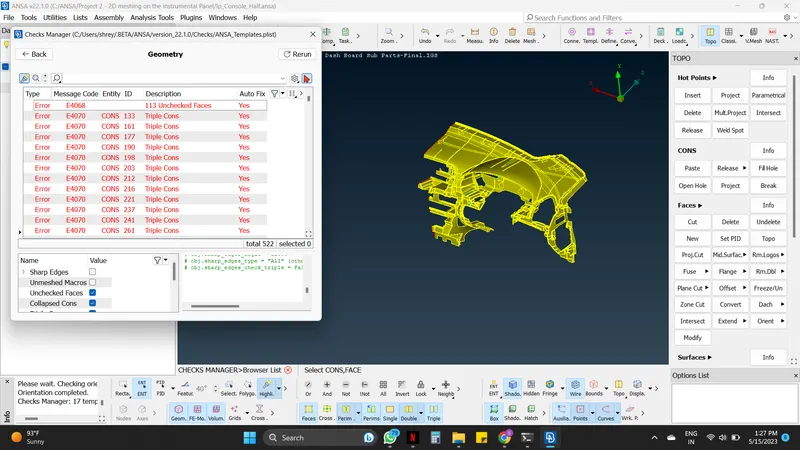
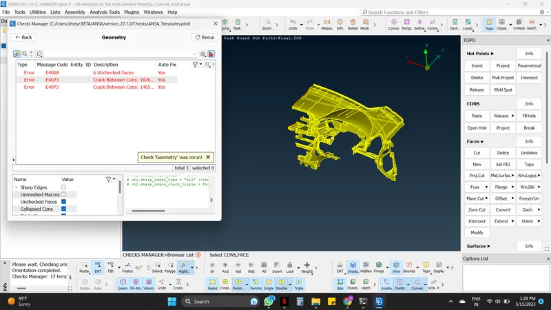
Step 03 : Setting up the Quality Criteria and Mesh parameter
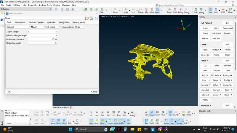
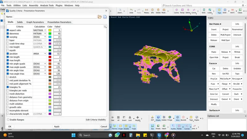
- Setting up the quality criteria as well as the mesh parameters is very important in every pre-processing process. This will make the mesh proper as per the requirements. Here the parameters are given, as per the given data fill the dialogue box, and apply to the component.
Utilities tab -----> Mesh Parameter -----> Set Element type: Mixed, target length, minimum target length -----> Ok
Utilities tab -----> Quality Criteria -----> From the Shell tab set 2D element qualities as per the given values -----> Ok
Step 04 : Mid-surface generation
- The mid surface is generated to reduce the complexity as by simplifying the cad model we get more accurate simulation results in a shorter time.
-
Taking measurements of thickness in random parts of the model gives the same value of thickness i.e. 1 mm, which concludes that it is a sheet metal component. So any mid-surface generation technique i.e. manual or automatic mid-surface approach for the model can be used.
-
For creating the mid-surface, the mid-surface Casting Approach must be used as the component is very complex.
-
The casting approach is the simplest and easiest of all. Takes very less time. In the Midsurface casting approach, the mid-surface and the meshing both are done at the same time.
Mid surface Casting Approach :
Topo module -----> Faces -----> Midsurface -----> Casting -----> Dialogue box will appear (Automatic Middle-Mesh Generator ) -----> Insert the Minimum thickness as 1 and target element length as 3 -----> Click Ok.
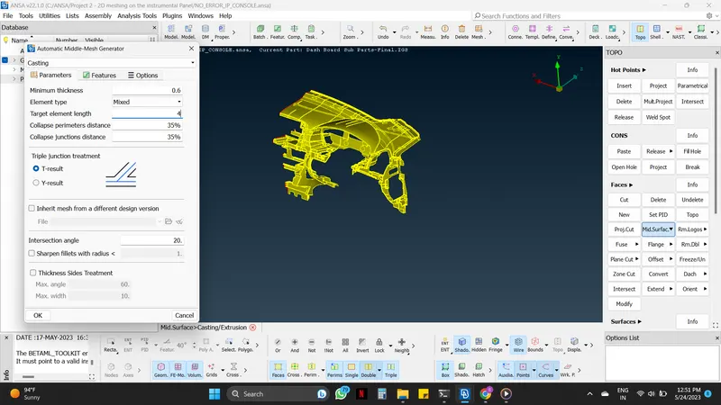
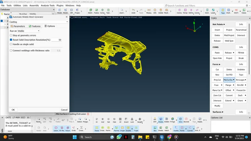
- After the Midsurface casting approach, the mid-surface extraction and the meshing is done.
- But as shown in the figures below there are many errors failing quality criteria, uneven surfaces, improper alignment, some surfaces are not extracted properly, Hollow sections are filled, and many more.
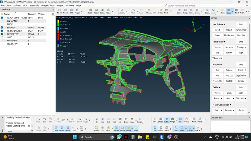
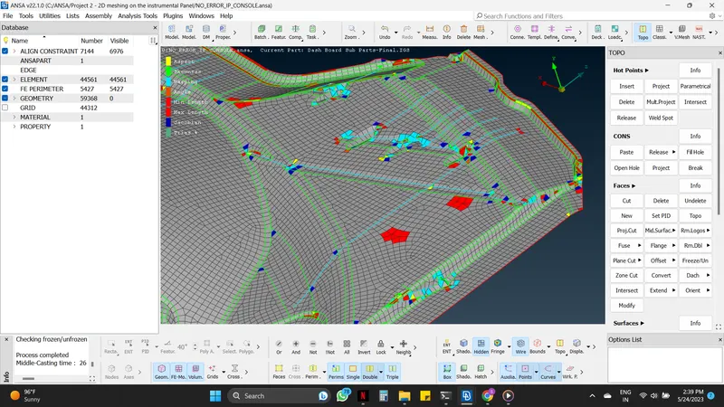
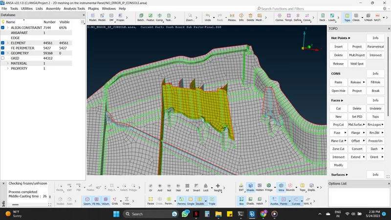
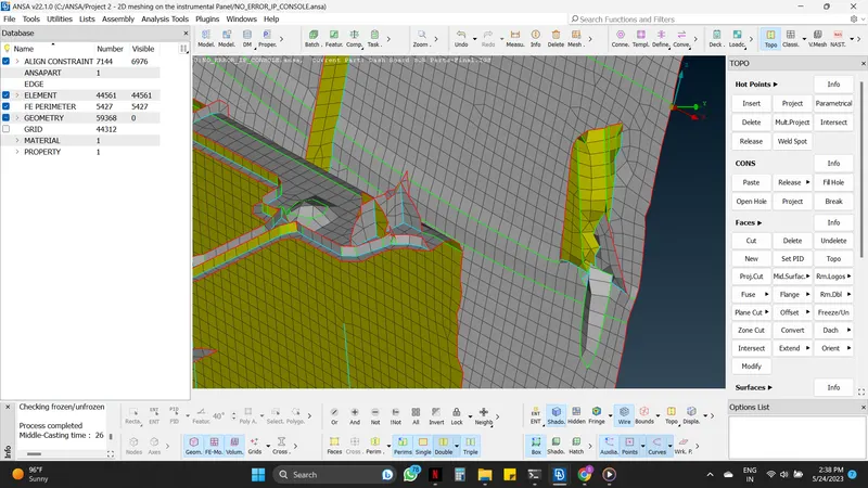
- These above errors must be cleared properly according to the parent geometry.
- For clearing these errors some basic and some technical commands must be used, they are as follows ;
BASIC COMMANDS :
| Sr. No. | Command | Steps |
| 1 | Smooth | Mesh module -----> Shell Mesh -----> Smooth. |
| 2 | Reconstruct | Mesh module -----> Shell Mesh -----> Reconstruct. |
| 3 | Split | Mesh module -----> Elements -----> Split -----> Mouse Left click splits quads into trias and Mouse Right click acts as Swap edge and combines trias. |
| 4 | Num+/- | Mesh module -----> Perimeters -----> Num+/-. |
| 5 | Swap | Mesh module -----> Elements -----> Swap. |
| 6 | Element Join | Mesh module -----> Elements -----> Join. |
| 7 | Macro Join | Mesh module -----> Macros -----> Join. |
| 8 | Delete | Mesh module -----> Hot Points -----> Delete. |
TECHNICAL COMMANDS :
- Below are some Technical commands which must be used while clearing the errors and obtaining the desired meshing and the mid surface.
- While performing these technical commands, the engineer must try different approaches according to get the proper and perfect result and for that, the steps may vary.
| Sr. No. | Command | Steps |
| 1 | Grid Paste | Mesh module -----> Grids -----> Paste -----> Select the nods which need to be pasted with each other -----> Mouse middle click. |
| 2 | Imprint | Topo module -----> Faces -----> Midsurface scroll down Align manager -----> Imprint ---> Select the lines which need to be on the mid surface -----> Mouse middle click. |
| 3 | Align | Topo module -----> Faces -----> Midsurface scroll down Align manager -----> Align ---> Select the elements which are uneven -----> Mouse middle click. |
| 4 | Curves Create | Topo module -----> Curves -----> Create -----> Draw the curve on the rib as required -------> Mouse middle click. |
| 5 | Fill | Mesh module -----> Shell Mesh -----> Fill -----> Select the nods -----> Mouse middle click. |
| 6 | Cons 2 Curves | Topo module -----> Curves -----> Cons 2 Curves -----> Select the lines -----> Mouse middle click. |
| 7 | Curves Middle | Topo module -----> Curves -----> Middle -----> Select the lines of one side -----> Mouse middle click -----> Select the lines of the other side -----> Mouse middle click. |
| 8 | Connect | Shell Mesh module -----> Modify -----> Connect -----> Select Target : Shells -----> Select the source which needs to be joined -----> Mouse middle click -----> Select the surface ---> Mouse middle click. |
| 9 | Perimeter Align | Topo module -----> Faces -----> Midsurface scroll down Align manager -----> Perimeters ---> Select the line which needs to be aligned -----> After selecting type will get highlighted -----> Right mouse click on it and select edit -----> Select the faces which must be aligned with the selected faces -----> Mouse middle click. |
| 10 | Surface Areas | Topo module -----> Faces -----> Midsurface scroll down Align manager -----> Areas ---> Select the surface which needs to be aligned -----> After selecting type will get highlighted -----> Right mouse click on it and select edit -----> Do the selection properly according to the color -----> Mouse middle click. |
- Using the above Basic and Technical commands the mid surface and messing is done according to the parent geometry.
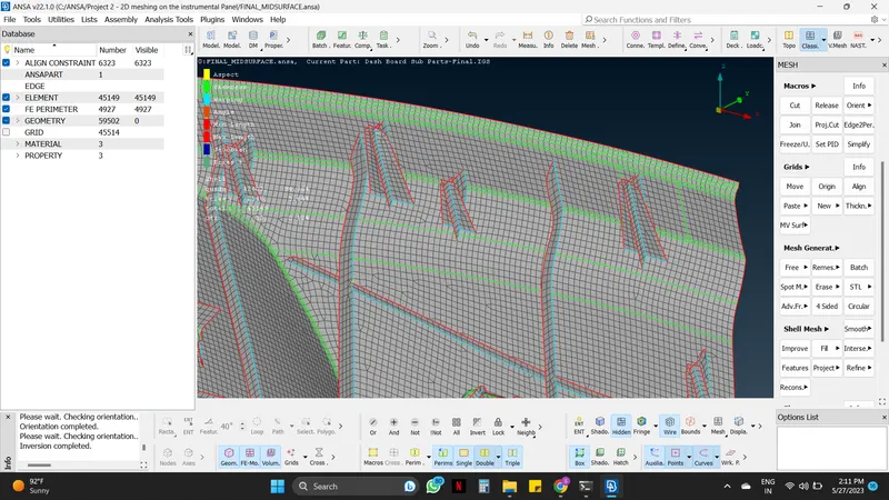
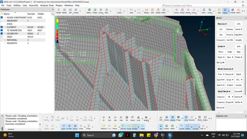
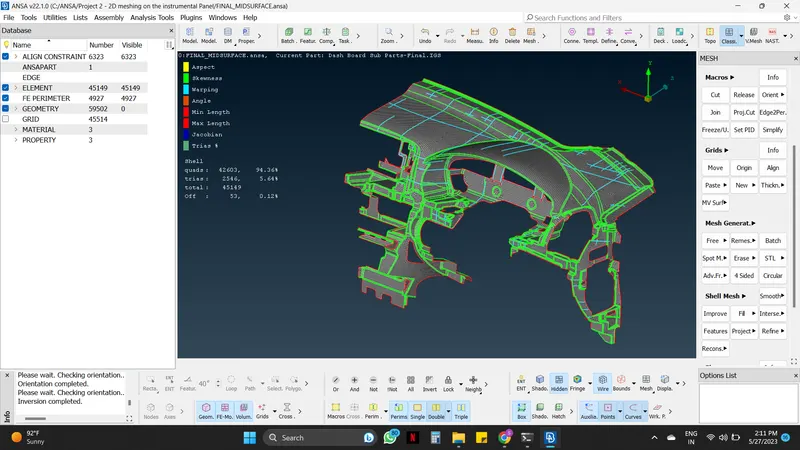
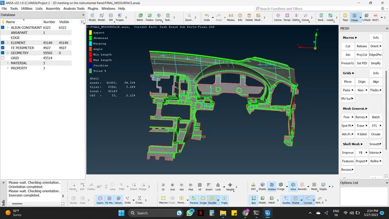
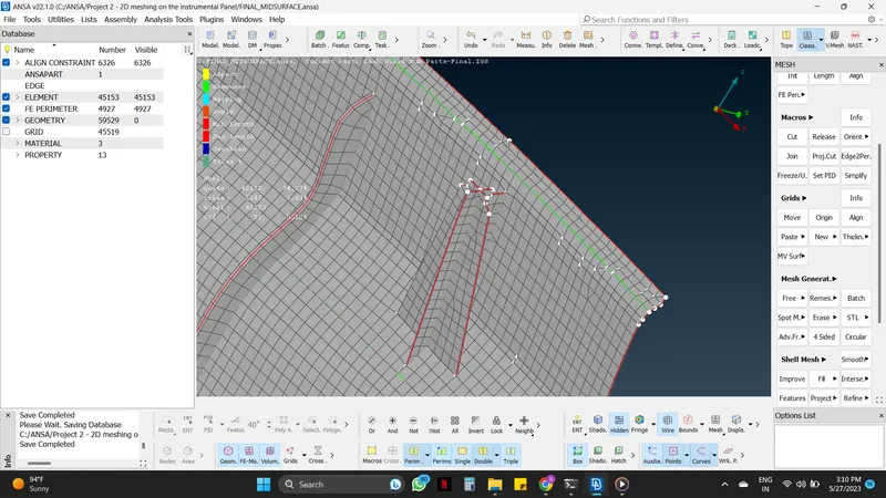
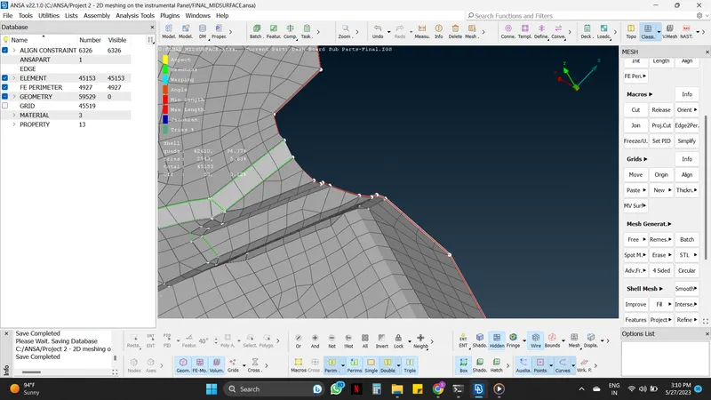
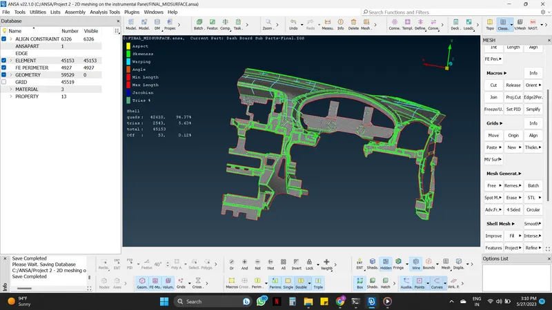
- Here there will be some off elements due to the triple cons, that off elements are acceptable.
- The final meshed Instrumental Panel component is obtained.
Step 05 : Assigning Thickness
- Thickness is given to the component for having a similar thickness at every element of the component.
Mesh module -----> Grids -----> Thickness scroll down Convert -----> Select the whole component -----> Mouse middle click -----> Finish.
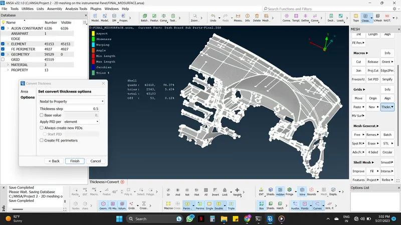
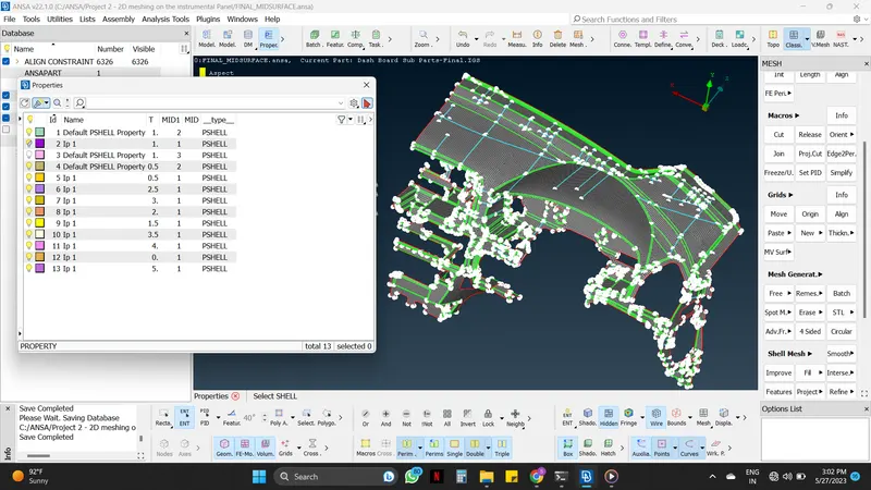
- While assigning the thickness all the different elements having different thicknesses will be assigned with different properties as per the assigned thickness.
Step 05 : Drawing shell as Solid
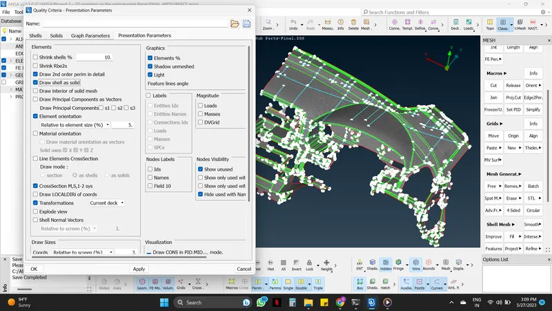
Utilities -----> Quality criteria -----> Presentation parameters -----> Draw shell as solid.
LEARNING OUTCOMES :
By doing this challenge, the following aspects can be learned:
- Perform geometry cleanup for any complex Sheet metal components (Instrumental panel).
- Generating a mid-surface and Mesh with different approaches.
- Identify the quality failure and resolve the failure & improve the mesh quality using align manager and basic as well as technical commands.
- Work on ANSA with a flow.
CONCLUSION :
- In this project, there were many non-uniform surfaces, ribs, and hollow surfaces which can be meshed properly with the align manager.
- With the align manager complex surfaces can be easily generated and meshed by using different approaches as per the engineer requirements.