Project 2 - 2D meshing on the instrumental Panel
Project-2-2D Meshing on Instrumental Panel
Aim :
To perform geometry editing, mid-surface extraction, and meshing on the given Instrumental Panel CAD model.
Procedure:
Step 1: download the geometry and check for possible errors: Downloaded the geometry and understood the design. Possible errors were checked, refer to Figure 1.
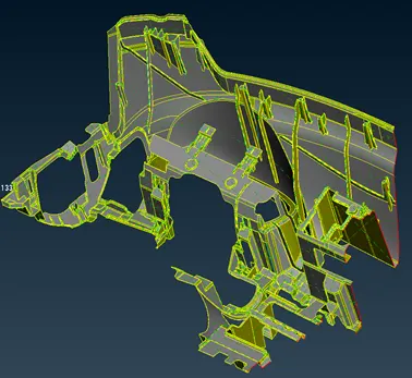
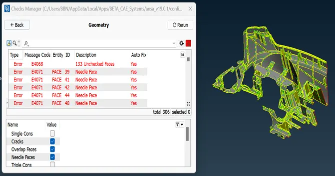
Figure 1: Represents the Instrumental Panel geometry and its geometry checks.
Step 2: Remove the geometry errors by topology clean up: The unwanted edges and points surfaces are removed and the triple cone is removed. Open regions were filled by creating new surfaces, refer to Figure 2.
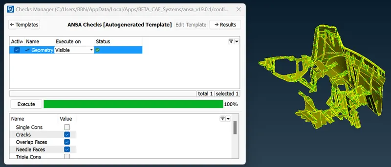
Figure 2: Represents the Instrumental Panel geometry cleaned.
Step 3. extract mid-surface: Mid-surfaces are extracted using auto mid-surface and offset surface operations. Created suitable partitions to make good mesh flow. Errors were fixed automatically and some of them were modified manually also.
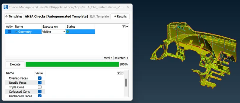
Figure 3: Represents the Instrumental Panel geometry with mid surfaces
Step 4. Assign mesh using best mesh option and check for quality: 2D meshing was performed using the best mesh operation and using reconstruct operation to rearrange the mesh. Some partitions were suppressed to get better mesh flow, refer to Figure 4. The quality of the mesh was regulated as per Figure 5.
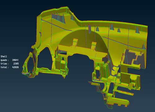
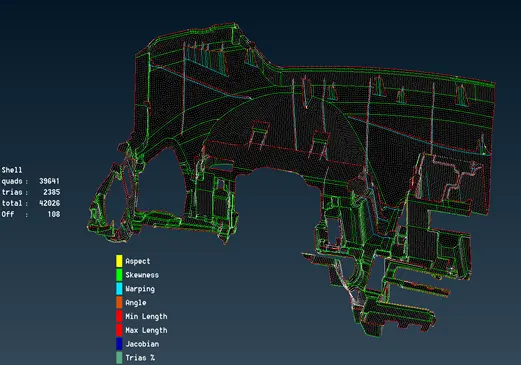
Figure 4: Represents the Instrumental Panel geometry meshed and its quality representations.
Figure 5: Represents the quality criteria.
Learning outcomes.
- With this task, I learned how to extract the mid-surface and meshing of the Instrumental Panel components.
- I used an additional set of operations like extend, create, extrude, and offset surfaces.
- I used the curves operation to make the surfaces.
- Using cut operation surfaces are partitioned to make good mesh flow.
- Performed auto mid-surfacing.
Conclusion.
Geometry editing, mid-surface extraction, and meshing were performed in the Instrumental Panel component.