Project 2 - 2D meshing on the instrumental Panel
2D MESHING OF INSTRUMENT PANNEL
1.
Aim: To mesh the entire part with 2D quads & tria elements maintaining the quality criteria
as per the requirement.
2. Procedure-
This project is tried using two procedures:
1. Using manual midsurfacing & meshing
2. Using the auto meshing by casting Process
PROCEEDURE-1 : USING MANUAL MIDSURFACING & MESHING
A. Geometry Clean up:
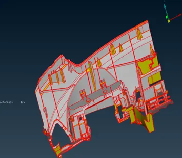
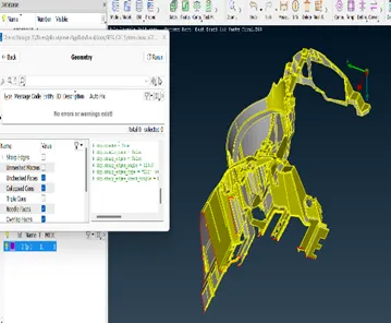
The entire geometry of the part is analysed for its thickness, cons etc. The initial model provided as red cons all over its edges as shown in the image. Hence, by using the TOPO technique we convert these red cons in to suitable one (yellow or blue).
 |
 |
|
Before clean up |
After Clean up |
In the process of geometric cleanup there are no of surfaces found to be unchecked. Those surfaces were deleted & created again.
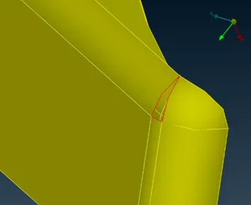
In the above image the region with the red con was an unchecked surface. However, that surface was deleted and substituted with a new one in order to obtain an error free geometry.
A. THICKNESS MEASUREMENT
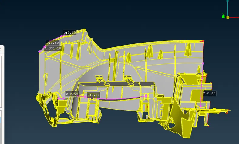
The outside body panel has an uniform thickness of 0.6mm everywhere. So the mid-surfacing could be achieved accordingly.
A. MID-SURFACING:
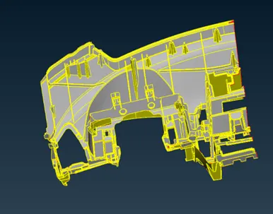
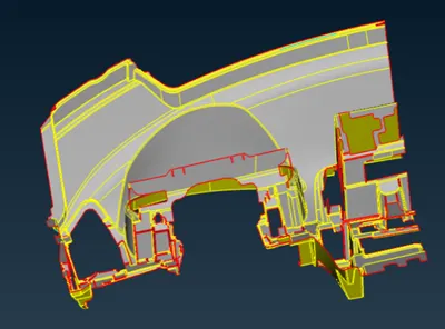
Once the thickness is measured, mid-surface is obtained for this uniform thickness part
 |
 |
|
ACTUAL MODEL |
MIDSURFACE OF OUTER REGION |
Here initially midsurfacing of the outer region having the uniform thickness is completed first using the offset method, where the offset is set to 0.3mm
However, the procedure one has to be stopped right there, due to following reasons:
|
Reason-1 |
Due to the complicated geometry of the instrument panel, the mid surfacing & meshing was very difficult |
|
Reason -2 |
Even after working for about 10 hours, only 50% of the model was mi surfaced & meshed |
|
Reason-3 |
Using Auto meshing by casting, we don’t need to worry about the varying thickness of the model. |
PROCEEDURE-2: USING AUTOMESHING
Using casting model, we obtained an accurate FE model capturing all the features.
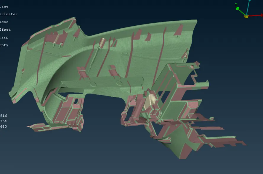
The above FE model was obtained using the Casting/Extrusion within a timespan of 20 min. Comparatively much lesser time than the manual meshing.
a. LIMITATION OF AUTOMESHING:
Auto meshed results are not 100% accurate. There will be some regions which has to be corrected manually
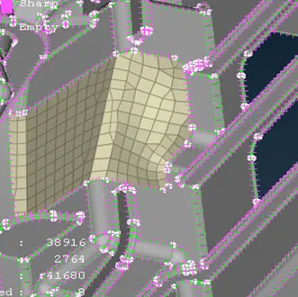
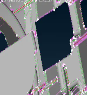
Below shown are some examples, which are major like Doghouse & the extra meshing of hollow region.
The corrections are made on many of the doghouses
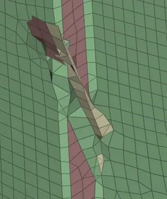 |
The Doghouse region mostly gets Distorted, which has to be corrected manually |
 |
Some regions were meshed, where there is no requirement of meshing. Which has to be deleted. |
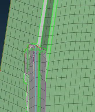
a. CORRECTIVE ACTIONS:
|
 |
|
Initially Distorted Doghouse |
Corrected Doghouse |
|
 |
|
Extra Meshing |
Elements Deleted |
a. TOOLS USED IN CORRECTIVE ACTIONS:
The following are the major tools, which will be required to correct the mesh flow & the feature capture
1. 1. Align manger
2. 2. Connect --à Middle mesh
3. 3. Delete elements
4. 4. Move elements
5. 5. Cons2curves
6. 6. Fill
7. 7. Smooth
8. 8. Reconstruct.
Please find the challenge in this drive link https://drive.google.com/drive/u/0/home
https://drive.google.com/file/d/10XTfh5Bl-PLZtvQQ2flsr2XU2WObhIfp/view?usp=sharing
https://drive.google.com/drive/u/0/home
.