Project 2
Rear supension system
AIM:To extract the mid-surface, 2D surface meshing, and volume meshing as per the Quality criteria in ANSA for rear suspension CAD model and also providing necessary connection using Nastran.
Introduction and sequence of operations performed.
- Geometrical clean-up
- Mid surface Extraction and 2D meshing
- Volume Meshing as per the Quality criteria
- Set PID’s for each part.
- Connections using Nastran
Before we perform any operation the model we need to perform the Topology on CAD model to entry mode. This operation gives us perfect model without any cracks and orientation of the each part in the model.
Here is the initial stage of the model when we imported or converted into ANSA file. We can observe the no connection between the faces.
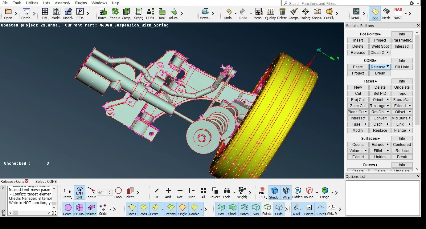
After Topology performed on the model.
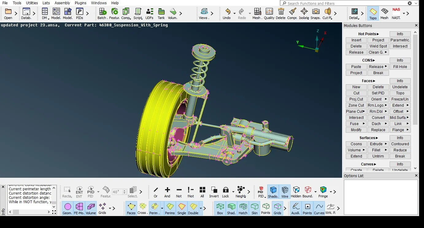
Geometrical clean up:
This is one of the important area we need to clean up the model where triple cones, concave, convex and cracked geometrical errors occurred in the CAD model.
- Cleaning-up the triple, concave , cracked surfaces and mixed etc.
- Triple cons: multiple edges joined at one place , more than two edges.
- Mixed cons:combined edges or faces.
- Cracked face: slight gap or slit on the surface or gap between the two edges.
- Concave or convex :overlapped boundaries of the faces.
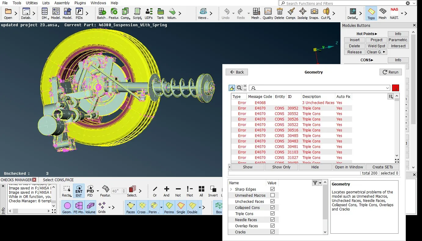
After geometry clean-up model is free from all geometrical errors.
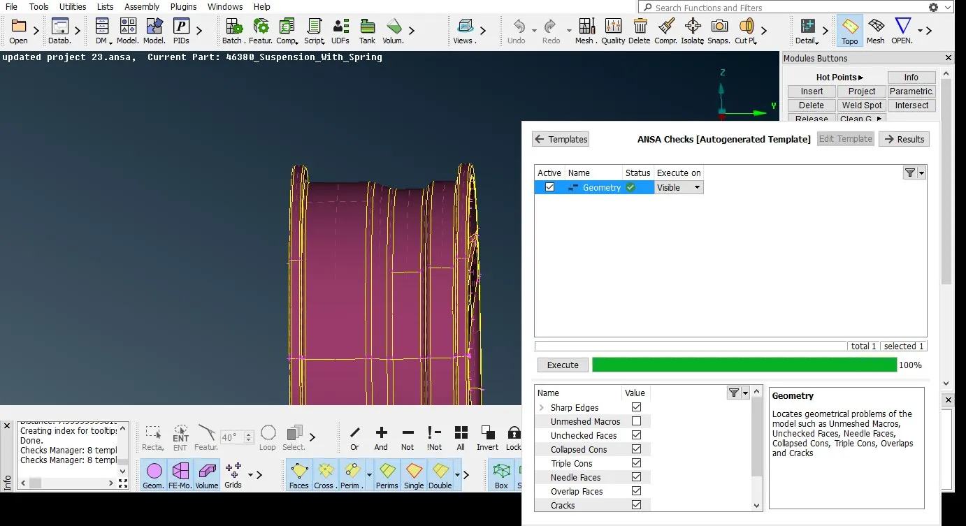
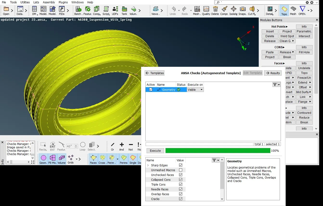
We have checked all the parts separately we can see here the green bar which means geometry free from all the errors 100%.
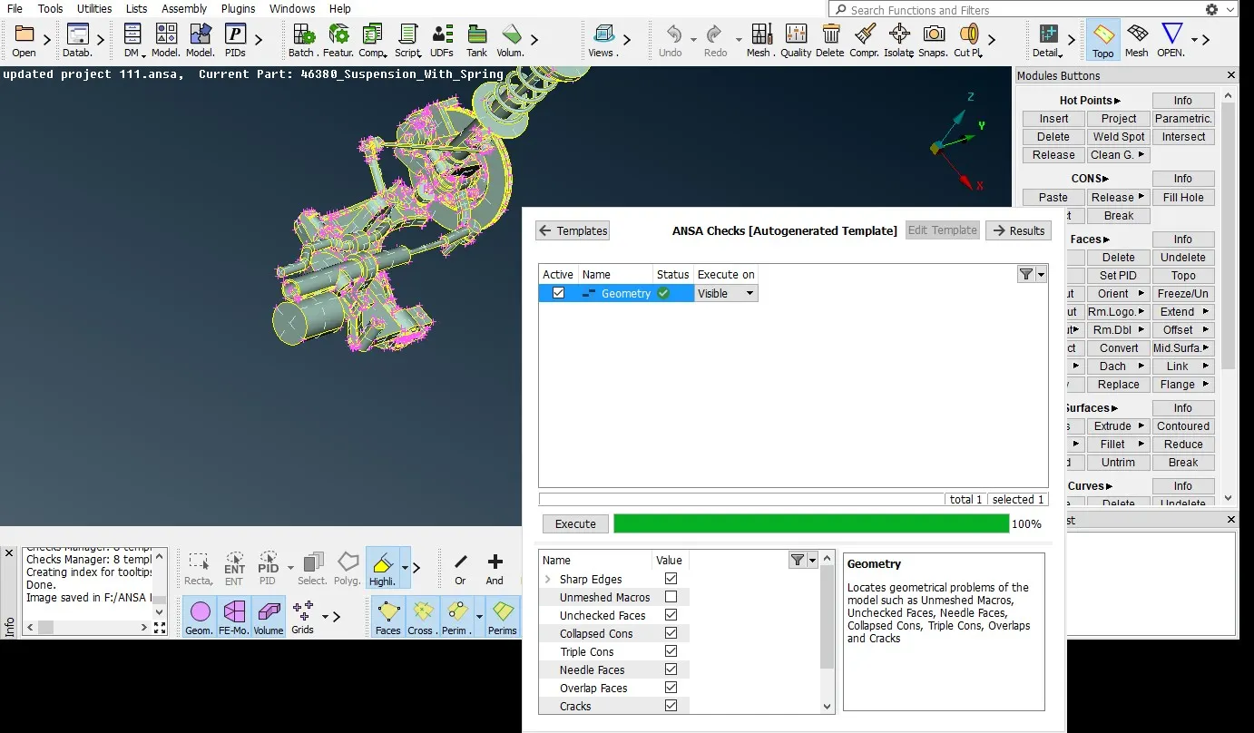
All the geometry errors made cleared for each part separately
MID- SURFACE:
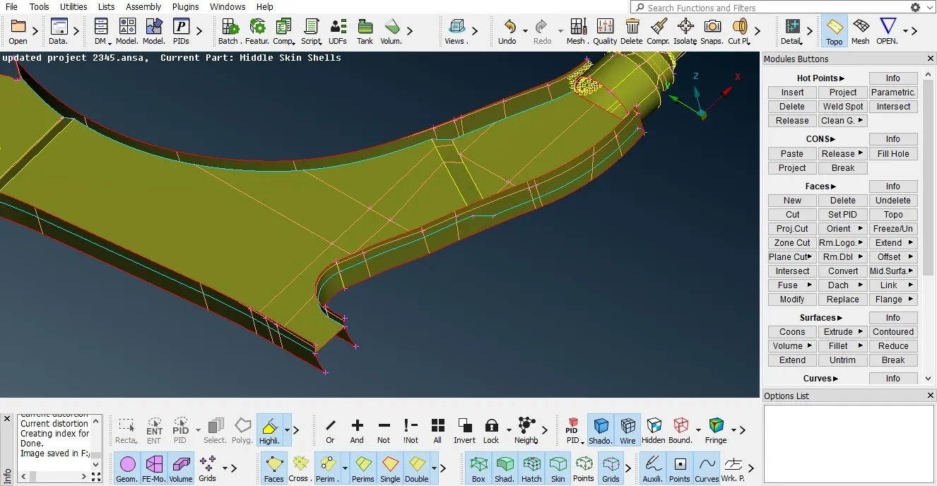
Mid-surface extraction for uniform thickness and thickness less than 5 mm as per the requirement.
Usually we have OFFSET method, middle and auto mid-surface (skin and caste).caste command and offset best way to extract mid surface here.
After mid surface extracted there would be gap between the horizontal and vertical surface so we need to use extend tool to join the surfaces but in auto mid it is difficult to use extend option after mid-surface extraction. That is why we have to use offset or skin without any distortion in the geometry.
MESHING:
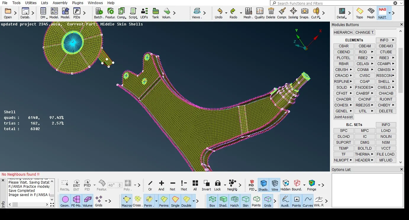
Before going to mesh the model we need to update the quality criteria and mesh quality as per the given quality data for the object. We need to choose the following details to get proper or smooth mesh. I have used best mesh generation tool here.it challenging to generate mesh manually each and every part to understand the quality.
Surface meshing algorithms using tria and ortho-tria element type meshing as per the mesh parameters given. Spot- mesh or (batch mesh) gives us fine mesh result and gives us optimum shell elements compare to other mesh.
We need to select the mesh type as per the QC
For Tyre and rim - ortho-tria meshing at mesh parameter and quality criteria
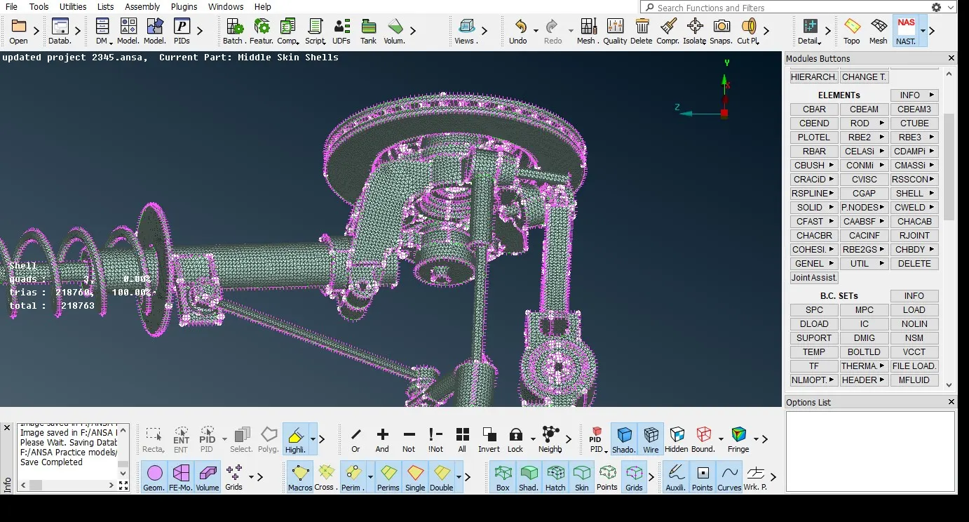
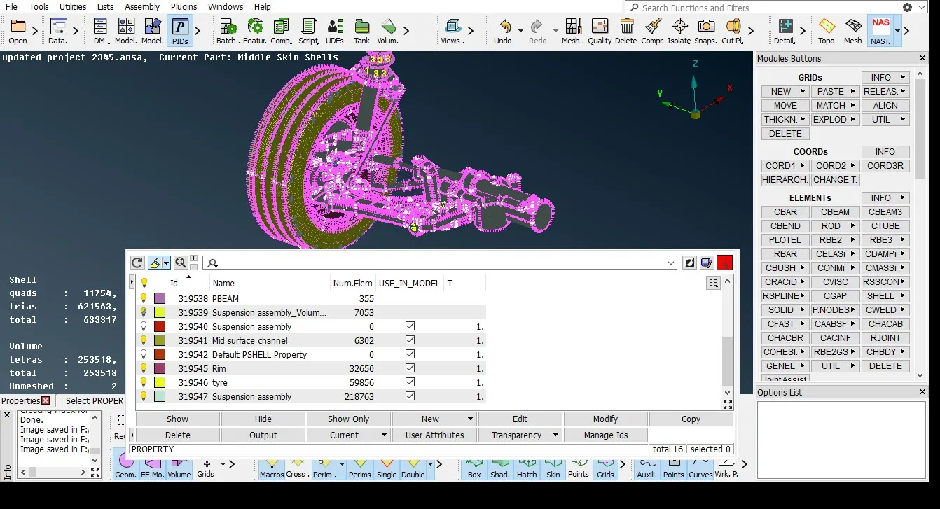
Part ID is given for each component separately as per the thickness.
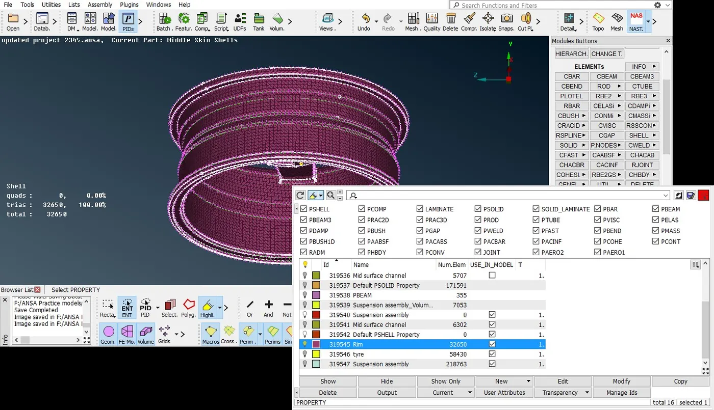
Define the solid mesh part by selecting the option AUTOSELECT, MANUAL.
Volume mesh →Define → Auto-select and Manual → Manual select
Select the tetra Rapid and tetra FEM in volume mesh to generate 3D mesh
Tetra Rapid mesh:
The maximum growth rate, which is approximate growth factor of volume elements from layer to layer while the generation moves towards inside from surface.
Tetra FEM:
It is defined from volume module.it creates tetrahedral mesh inside automatically when we selected it from the define command. It used for structural applications.
Below we can see the volume mesh 3d elements flow.
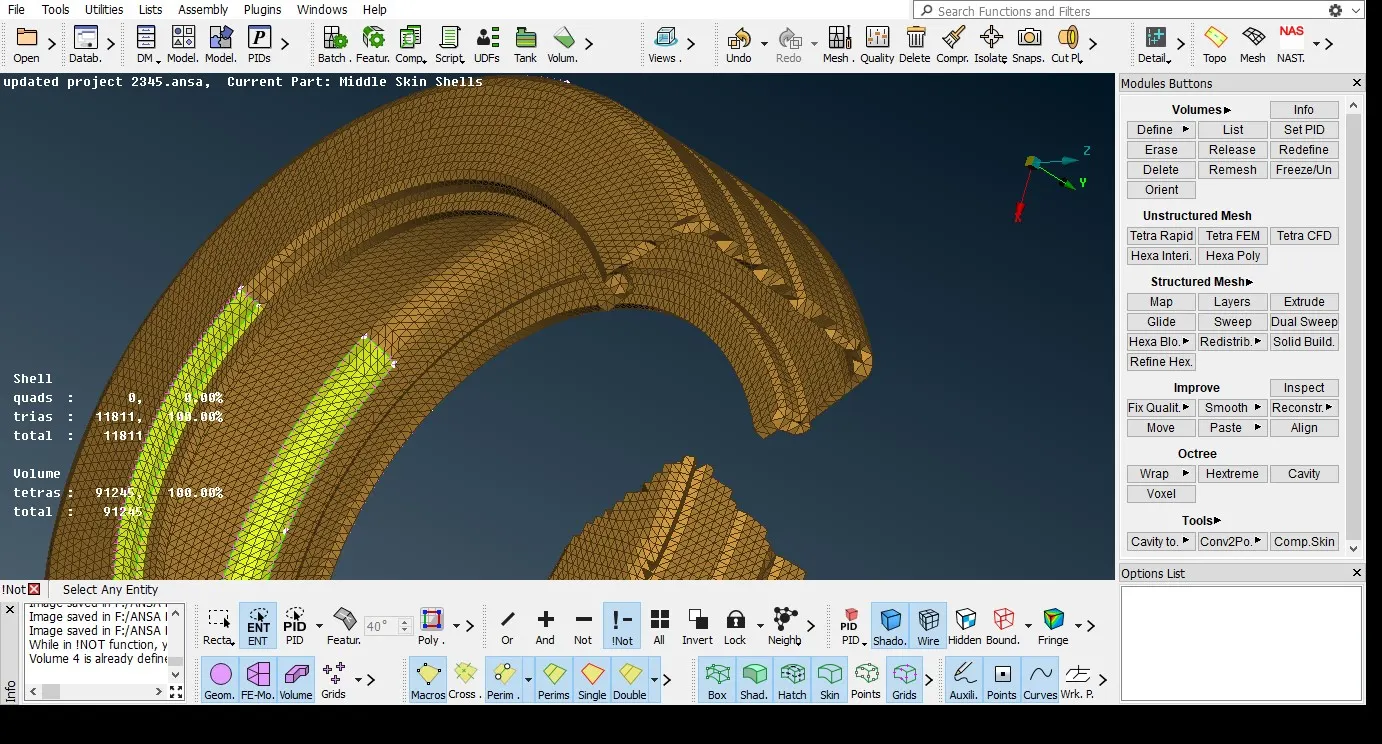
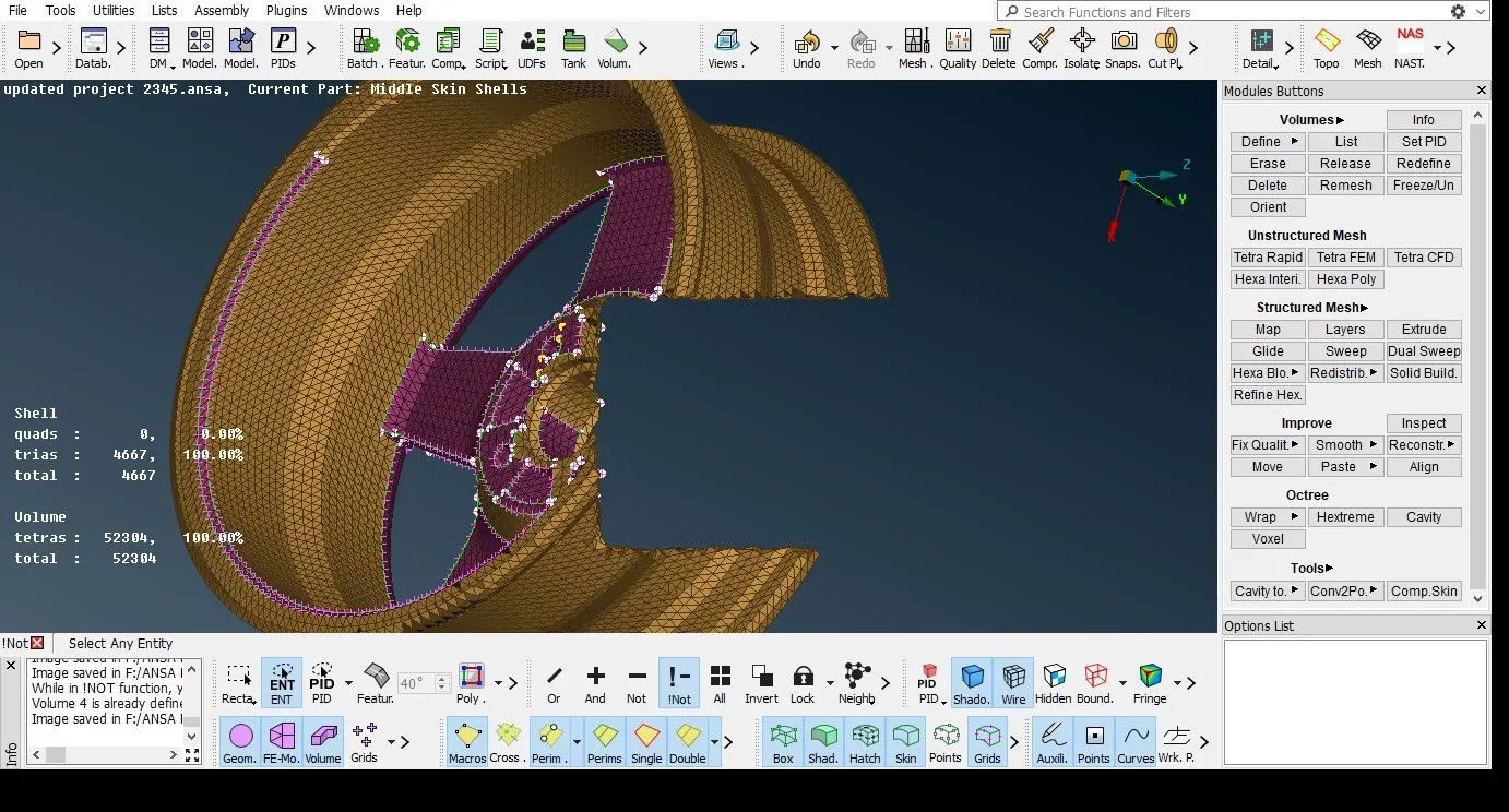
To meet the quality criteria we need to check the raising and collapsed elements which fall below the quality. We have tools available in mesh module MVfree and Align both are useful tools to improve the quality as well as to meet the criteria.
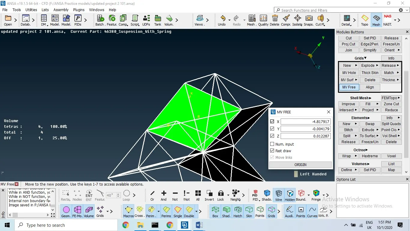
CONNECTIONS- NASTRAN MODULE:
We have different types of connections to join the parts using Nastran module in ANSA
Basic assembly connection types:
These connections are available assembly, helps to join through bolts, seamline, spot-welds, curves, fe to adhesives etc. First we need to convert the connection 3D points or any other required joining method according to the joining type.
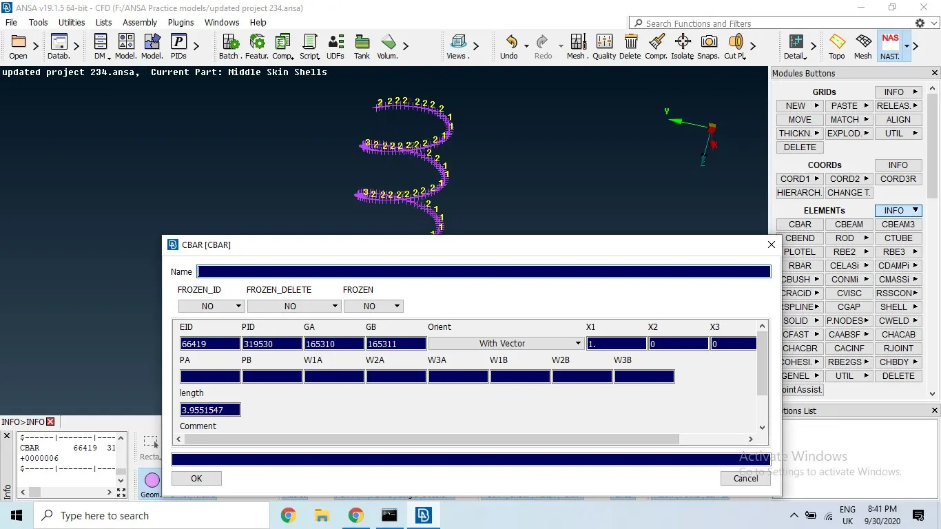
Nastran→ elements→ CBAR→ curve seg →section parameter.
In section parameter we have to assign the value as per the geometry like cinder and rectangular plate in which we have to give the value.
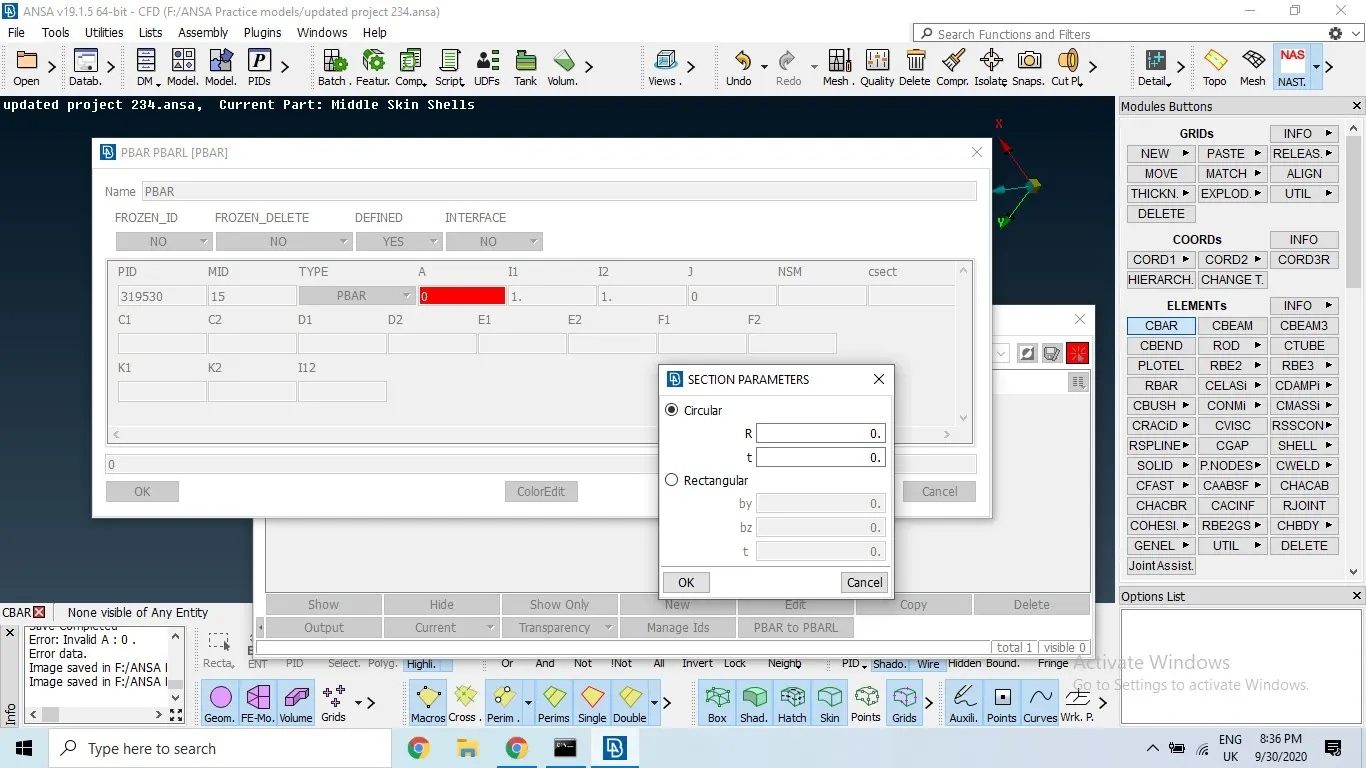
Method of connection1: Assembly→ convert→ 3D point or curves etc. →selecting the connection manager
Method of connection2: first we need to create 3D pint then selecting the RBE2 (rigid body elements) at elements in Nastran module to create the connection. We can select many nodes to create rigid body connection to join the bolt connection we can use two node RBE2 to establish the bolt connection.
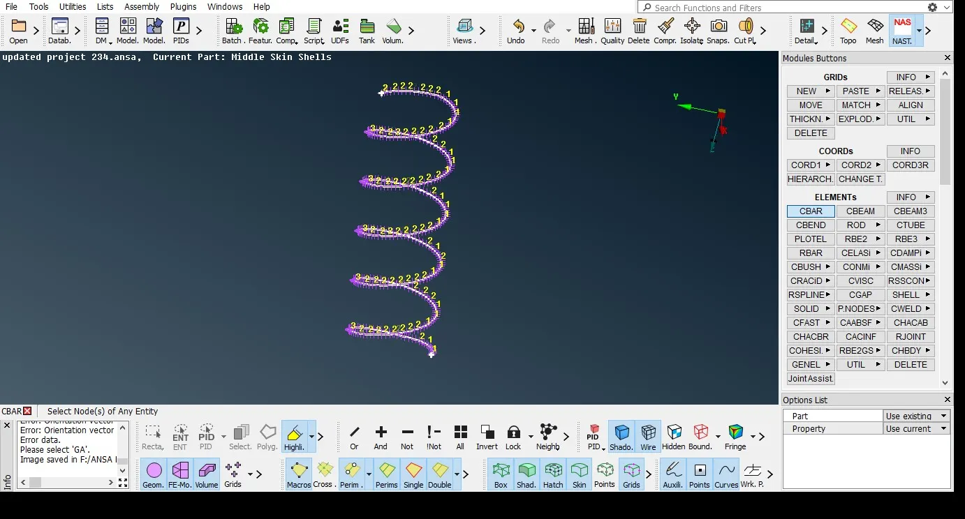
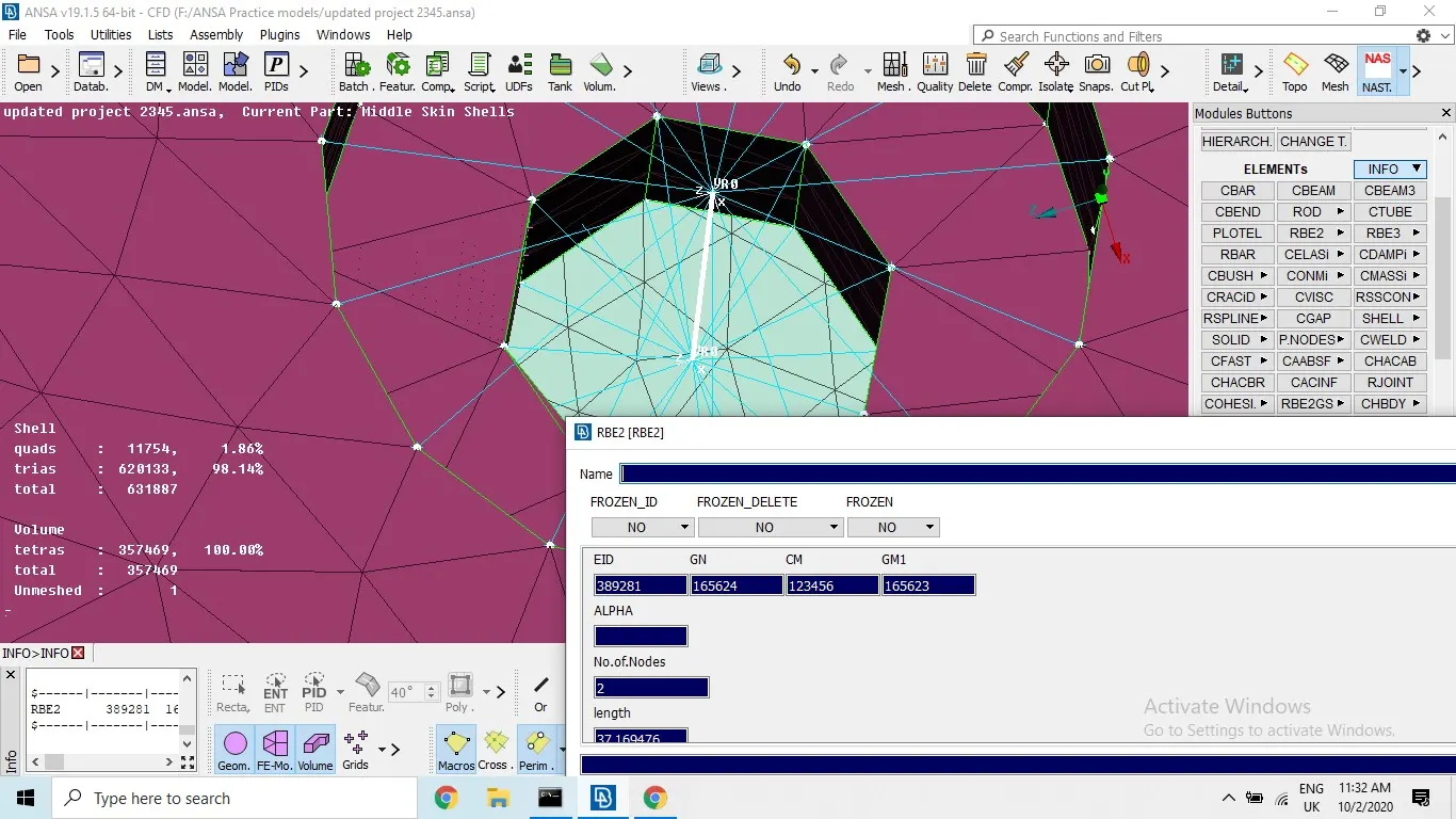
Below image about part ID and information saved regarding connection with necessary information
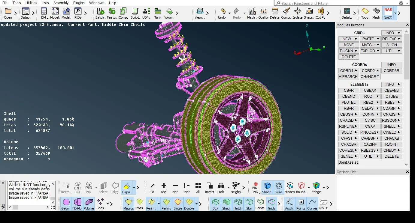
This is the final model after mid-surface, meshing (surface 2D, 3D volume mesh) and connections.
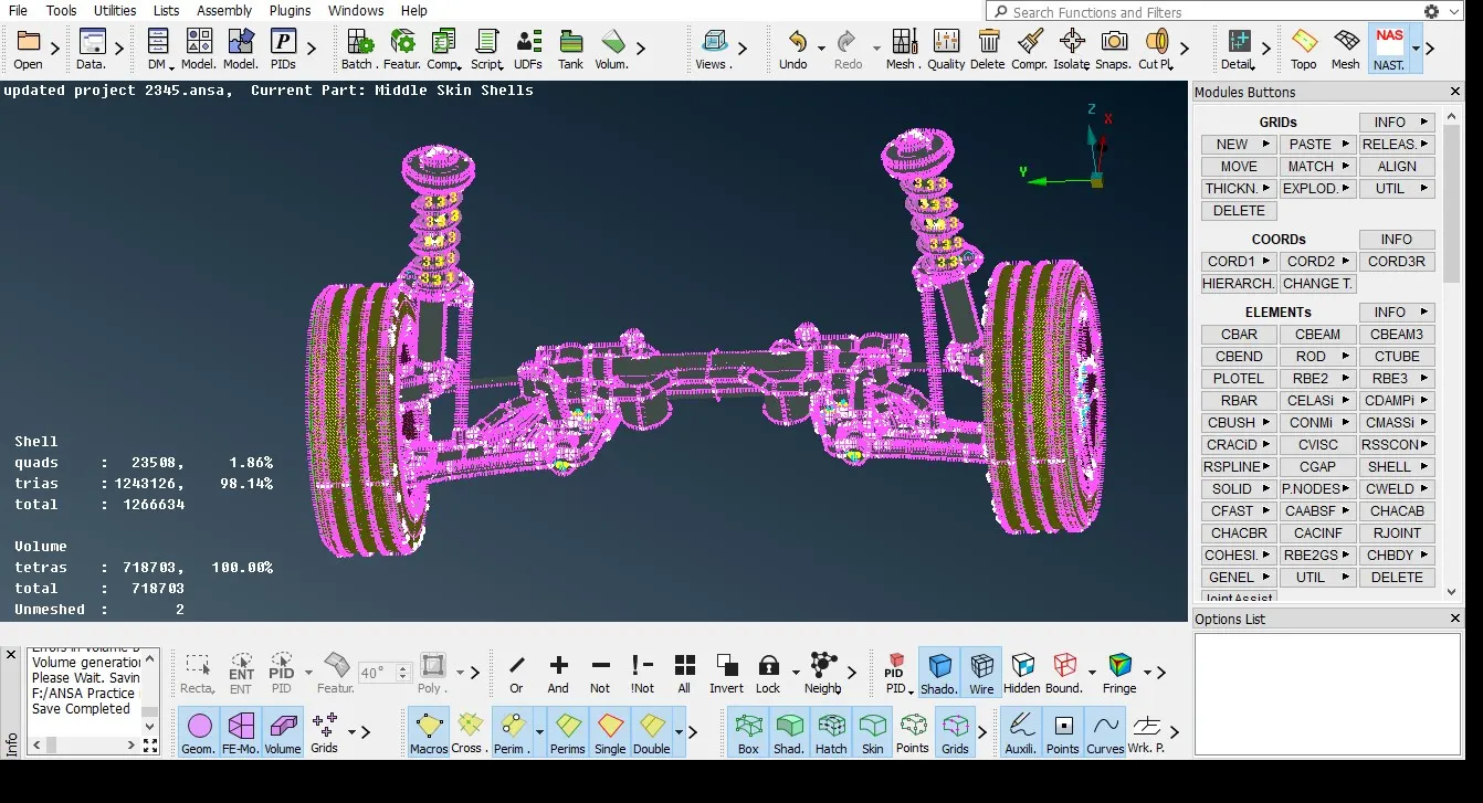
After reflecting the model using transform command.
Transform→ copy→ symmetry →selecting mirror plane then select any three points on the circular section then click ok.
Outcomes:
- Learned how to use Extend tool after extracting the middle surface to join the planes
- Understood the complexity of the rear suspension meshing and clearing collapsed elements in both 2D and 3D meshing.
- Learned to use volume, 3D meshing on solid models and shell mesh.
- Learned how to bring the mesh flow smooth.
- Used CBAR tool for coil spring in Nastran to give the connection.
Conclusion:
The rear suspension system of given CAD model meshing 2D, 3D and volume mesh has done in ANSA also made necessary connection in Nastran as per the Quality criteria .Generated mid-surface for some parts in the suspension system and some parts of the suspension system. Then the model reflected into full image.
https://drive.google.com/file/d/1mdHV_TGtNRrhygnOf7_dt5oJle43JrDy/view?usp=sharing