Project 2
PRE-PROCESSING OF A SUSPENSION MODEL BY ANSA
AIM: The main of this project is to do the complete preprocessing for a suspension model by using ANSA.
OBJECTIVE: Objective of the suspension system is to perform volume meshing and maintain Quality criteria for the meshing process and perform the required connection type.
INTRODUCTION:Suspension is the system of tires, tire air, springs, shock absorbors and linkage that connects a vehicle to its wheels and allows relative motion between the two.Suspension systems must support both road holding/handling and ride quality, which are at odds with each other. The tuning of suspensions involves finding the right compromise. It is important for the suspension to keep the road wheel in contact with the road surface as much as possible, because all the road or ground forces acting on the vehicle do so through the contact patches of the tires. The suspension also protects the vehicle itself and any cargo or luggage from damage and wear. The design of front and rear suspension of a car may be different.An early form of suspension on ox-drawn carts had the platform swing on iron chains attached to the wheeled frame of the carriage. This system remained the basis for most suspension systems until the turn of the 19th century, although the iron chains were replaced with the use of leather straps called thoroughbraces by the 17th century. No modern automobiles have used the thoroughbrace suspension system.
PROCEDURE:
STEP 1: IMPORT GEOMETRY
- After opening ANSA,import the model by using file command.

fig:Image showing the imported geometry.
STEP 2: ASSIGN PIDS
- Affter importing the model,assign pids for each part by isolating it from the model.
- To assign PID select the part,go to properties-new-pshell-pshell.
- This helps to identify the each part seperately.
- Assign different pid for every part.
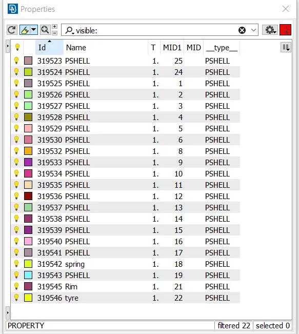
fig:Image showing pids for pshell.
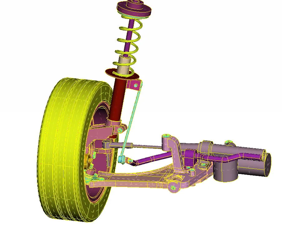
fig:Image showing the model in pid mode.
STEP 3:Quality criteria.
- The quality criteria should be followed is given below.
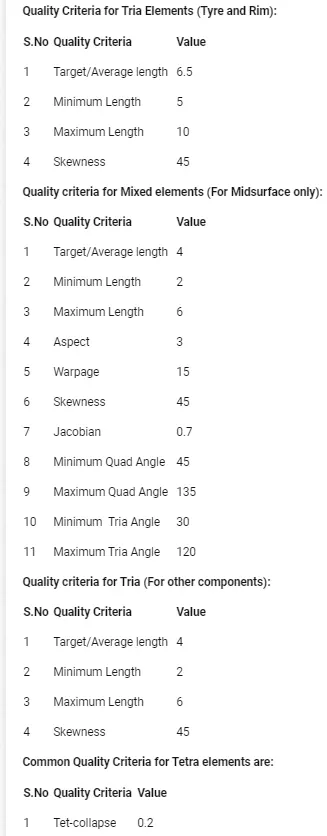
NOTE: Before Quality criteria every time check the model for errors. Do topo clean up for every part where element fail for the Quality criteria.This helps us to get a good mesh flow for surface mesh and reduce off elements in volume meshing.
STEP 4: SURFACE MESH
- After assigning PID do surface mesh for the model.
- Follow the quality criteria given,to the surface mesh.
- In mesh parameters enter target length and make sure the mesh is in tetra option.
- For this model we mainly do the volume mesh,because the model is hollow and the thickness is most of the cases is greater than 5mm.

fig:image shhowing mesh paramters for suspension system.
- After giving mesh parameters and quality criteria,isolate each part from the suspension part and perform surface mesh.
- Each part should be checked for geometrical clean up and checked for the minimum and maximum length.
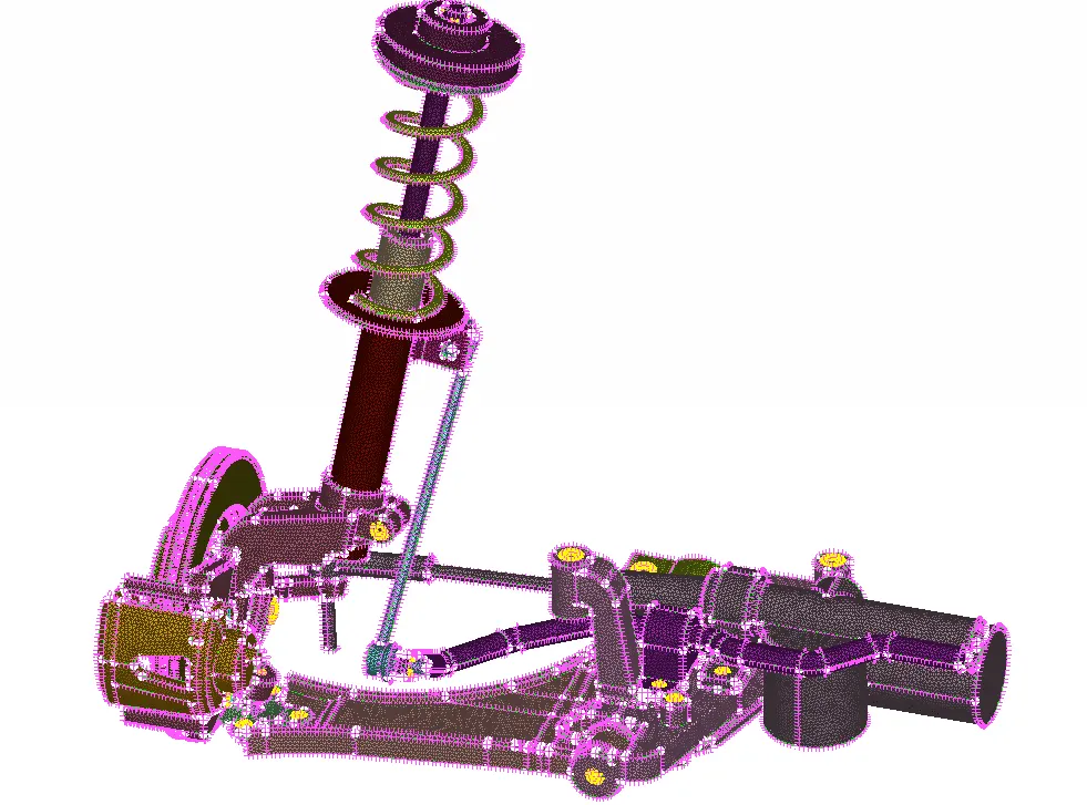
Fig:Image showing surface mesh for the suspension part.
- In the same manner do surface mesh for the tyre and rim part by selecting the Quality criteria.
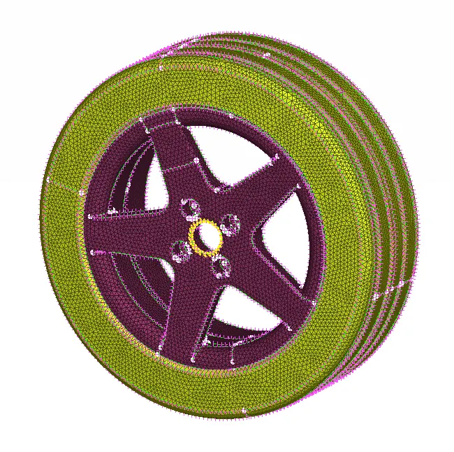
fig:Image showing surface mesh for tyre and rim part.
NOTE: Do not do surface mesh for both tyre rim and for suspension part,as there is different Quality criteria.
STEP 5:VOLUME MESH
- After surface mesh,isolate each part from the model and dp volume mesh for the model.
- Volume mesh is done when the model is hollow or the thickness is greater than 5mm.
- TETRA means unstructured mesh,i.e the flow will not be in sequal in volume.
- The mesh flow will be of unstructured.
- Isolate each part and perform volume mesh for every part by maintaining the quality criteria.
- For volume mesh we will follow only tet collapse errors for 0.2.
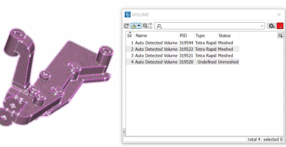
fig:Image showing a define volume which is unmeshed
- After defining the volume go to list tab and remesh the unmeshed model.
- Remesh either by tetra rapid or tetra fem.
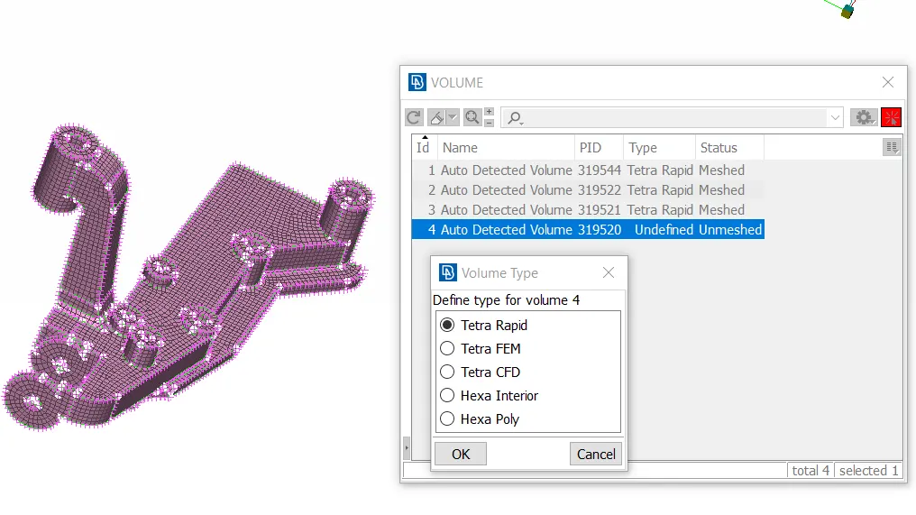
fig:Image showing table of tetra rapid mesh.
- When we perform tetra rapid ANSA will take some time and meshes the volume mesh.
- After volume is meshed check for the collapse errors.
- If present fix the Quality.
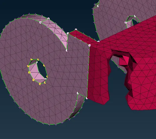
fig:Image showing volume mesh.
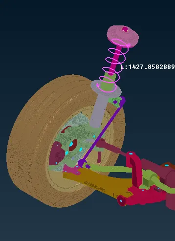
fig:Image showing volume mesh of the component.
- Atfer complete volume mesh switch off the geometry below and turn on volume,we can observe volume mesh of the model.
STEP 6:CONNECTIONS
- After doing volume mesh perform connections where ever required.
- These are important in ANALYSIS part.
- When there are spring type part perform CBAR connection.
- When there are bolts perform RBE2 connections.
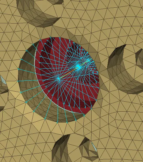
fig:Image showing bolt stem connection.
- This type of connectin is used when two or more parts are connected by a single bolt.
- Perform RBE2 connection on both parts,there will be master node for each part seperately, then connect them by RBE2 two node connection.
- The two master nodes are connected by a 2 noded RBE2 connection.
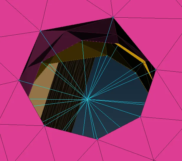
fig:Image showing cluster connection
- When two holes of same size are to be connected we can use cluster conection.
- This is called RBE2 cluster connection.
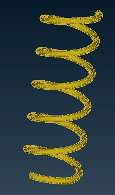
fig:image showing c bar connection
- When there are any springs or curved part then cbar connection is made.
- Take middle curve for the geometry,Go to cbar and define length.
- Go to pid of cbar connection and assign area.
- To see the c bar connection go to Quality criteria and turn on line element cross section as solids.
STEP 7:SYMMETRY THE MODEL.
- When complete part is finished including connection, make the model symmetry.
- To make symmetry we nedd to go to transform option.
- Select the complete model as ENTITY.
- Go to symmetry in transform and define 3 nodes in the model.
- ANSA takes some time and gives you complete model.
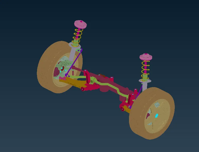
fig:Image showing the complete symmetry model.
MODEL BEFORE AND AFTER:
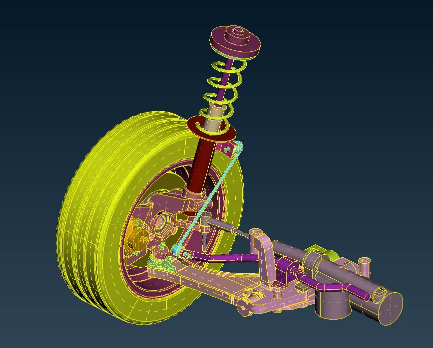
fig:Image showing the model before
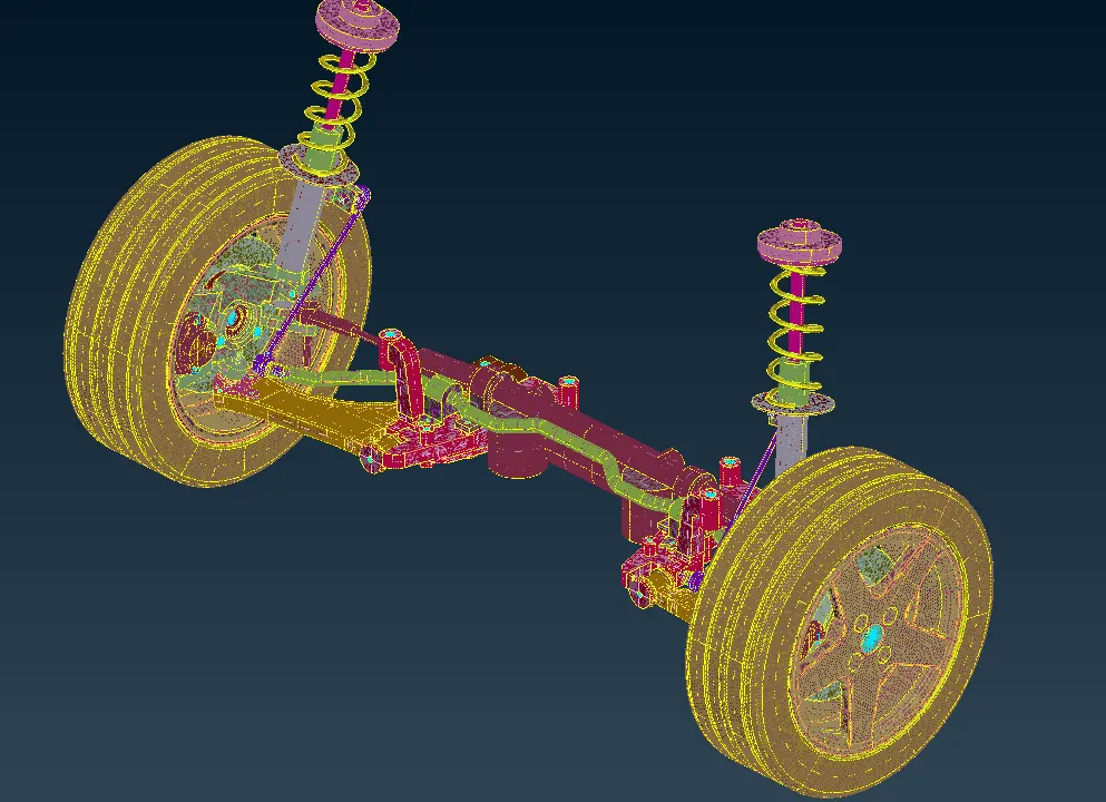
fig:Image showing the model after.
LEARNING OUTCOMES:
- Learnt how to mesh complex part.
- Got to know how to clear monute errors which does not allow volume mesh.
- Different types of connections in suspension system.
- How to use symmetry for different models.
CONCLUSION: Suspension system is the main part of the vehicle where it is useful for the passengers who sit in the vehicle and drive in comfortable.This part has to be get into Analysis stage as most of the load of the vehicle is observed by the suspension. The suspension system is pre processed and connections are made completely which can be go to the post processing stage.
LINK OF THE PROJECT: https://drive.google.com/file/d/1_48uYl41pfp-fLsmQcYx0BWimA1gOWSZ/view?usp=sharing