Mesh the Rear Suspension Assembly with Quality criteria using ANSA
AIM: To mesh the given Rear Suspension Assemble model based on quality criteria.
KEYWORDS: Topo, Tetra Rapid, Tetra FEM, Ortho tria, Aspect ratio, etc.,
SOFTWARE: Ansa
OBJECTIVE:
( i ). For the given Rear Suspension Assemble model check for Geometry clean up for each part & Topo the part.
( ii ). After the clean-up, use ortho tria mesh for Tyre & Rim and the rest of the parts to check the thickness.
( iii ). If the thickness is uniform and less than 5 mm then Midsurface (Mixed elements) is used otherwise perform with volume mesh (tria elements).
( iv ). Tyre & Rim, thickness exceeds 5mm parts, and midsurface parts as different quality criteria and perform the mesh operation accordingly.
INTRODUCTION:
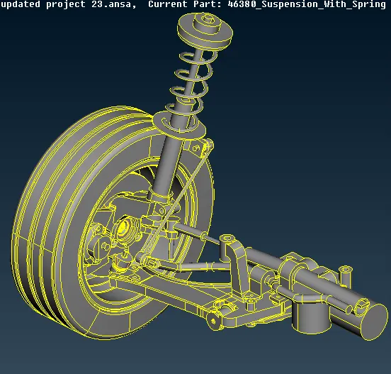
ANSA is a computer-aided engineering tool for Finite Element Analysis and CFD Analysis widely used in the automotive industry. It is developed by BETA CAE Systems. ANSA maintains the association between CAD geometry and the FE mesh. This means that the FE meshes are better representations of their geometric parents. Also, it is easy to maintain and update any changes in the geometry by simply reworking the updated area instead of recreating the FE from scratch. It carries several proprietary algorithms for meshing suitable for both CFD and structural models. ANSA was initially standing for 'Automatic net generation for structural analysis', but the software has gone beyond that very quickly. Here, Rear Suspension Assemble Model is to be meshed according to the quality criteria. The Actual model of the Rear Suspension Assemble as shown below,
( I ) GEOMETRY CLEAN-UP:
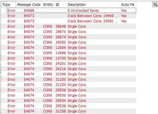
In ANSA software there certain kinds of tools used for geometry clean up, meshing and different types solvers to define certain problems. Initially, the CAD model should import into the software and check for geometry any error found. In this model geometry cleanup done for partwise (using PID region) and set PID for the part. There are certain types of errors like triple cons, single cons, unchecked faces, convex cons, etc., These errors can fix automatically & also manually. In this model some errors are auto-fixed and some fixed manually, the list of errors is shown below.
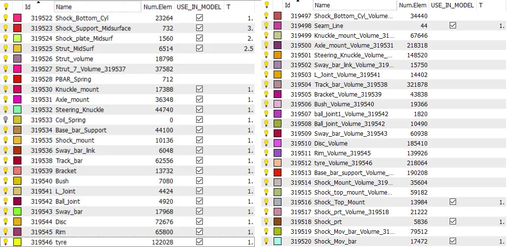
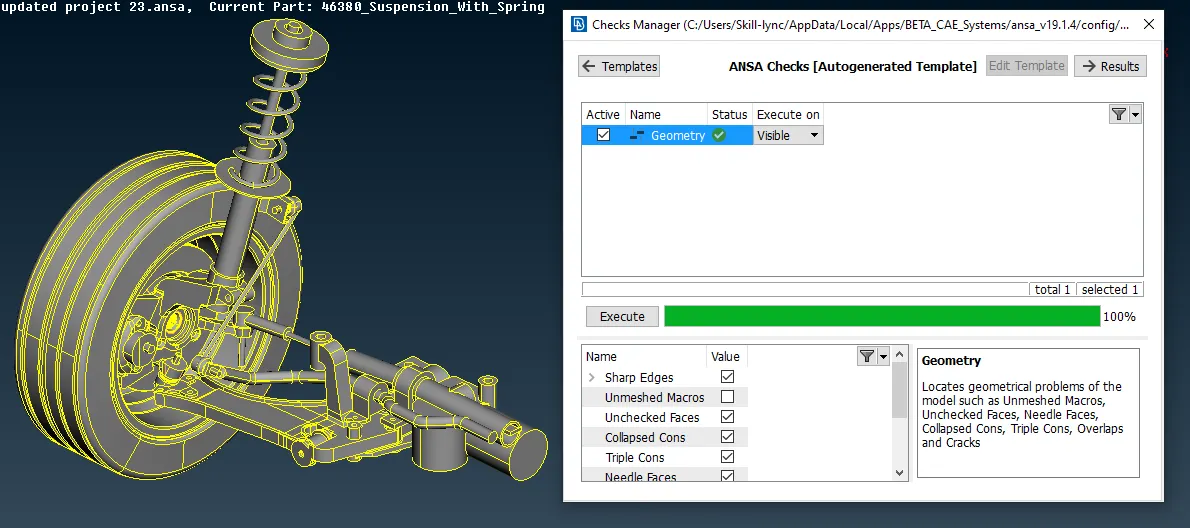
Before reading any CAD data into ANSA you can specify some settings concerning the application of Topology (the connectivity of neighboring Faces), and the Resolution (the appearance of geometrical entities on the screen). These settings should correspond to the dimensions, level of detail, and tolerances of the CAD. Here, the CAD model as Rear Suspension Assemble and the below figure shows that cleaned geometry partwise after did topo and related operations, which is ready to proceed with Mid_surface & Solid_Meshing.
( II ) MID_SURFACE (Thickness <= 5mm ):
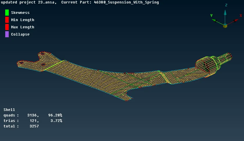
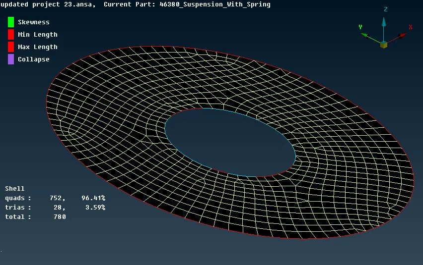
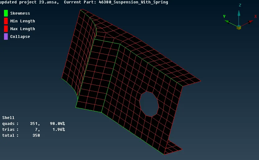
After completed the Geometry clean-up, the Model should proceed with Mid_Surface if the part has a uniform thickness that should not exceed 5mm. In Mid-Surface, it can be done with Auto or Manual. Auto midsurface can be done using the Casting & Skin option which should have a uniform thickness. Auto mid-surface will not work due to some complex features and irregular thickness present in the model so Manual Midsurface is suggested. Manual midsurface can be done by measure the thickness of the part and perform the offset option, some symmetry feature middle option can be used. There are some part which a thickness less than 5 mm as shown below,
1). Strut_Base_Plate:
2). Shock_Plate:
3). Shock_Side_Support:
(III ) MESHING:
After completed the Mid-surface with zero geometry error, the model is ready to mesh as per the quality criteria and some of the parts are undergone Solid meshing (tria) according to the quality criteria. In meshing, there are 3 types General, CFD & Standard, here the General type mesh is selected with mixed (both tria and quad) elements for Mid_surface, Ortho tria for Tyre & Rim, and Tria for the rest of the parts. In meshing, there are certain types of mesh used based on analysis and time constraints.
Types of Meshing:
- Manual Meshing
- Batch Meshing
- Mapped Meshing
- Auto meshing
( 1 ) Manual Meshing: In Manual meshing, the time required to mesh over all the components is more when compared to other types. For this component there are a lot of construction lines are arranged and modified based on proper mesh flow and quality criteria. In Manual meshing, the tria elements present is fewer, and also the mesh flow is better without any geometry modification. Time taken to mesh is depend on geometry complexity which includes a number of holes, features, free edge, etc.,
( 2 ) Batch Meshing: In batch meshing, the time required to mesh the overall component is less but the tria elements present are little more than the manual meshing. The mesh flow is good overall with the components. This method is used based on the time constraint and analysis.
( 3 ) Auto - Meshing: In Automatic meshing, the time required to mesh the overall component is less but the geometry is redefined near to the hole and in some features. In this component, the tria elements present is less than the batch mesh. The mesh flow in the overall composition is good. This method is used based on the time constraint.
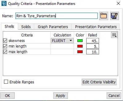
For this model, the Meshing is done with Manual meshing, because there is no much complexity in geometry, and when using tria mesh it's easy to do with Manual as well as Batch meshing. Before begin with meshing, we need to assign Quality criteria & mesh parameters.
QUALITY CRITERIA:
1). Tyre & Rim (Target_Length = 6.5):
2). Mid_surface (Target_Length = 4):
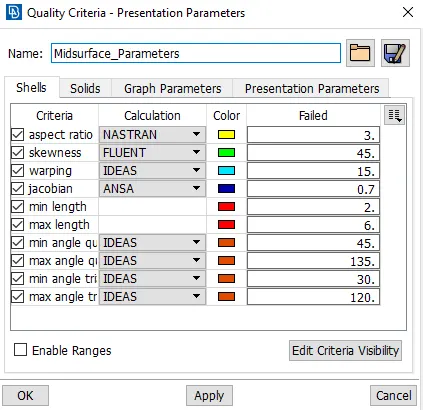
3). Other_Parts (Target_Length = 4):
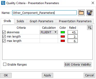
( i ) Structured Mesh:
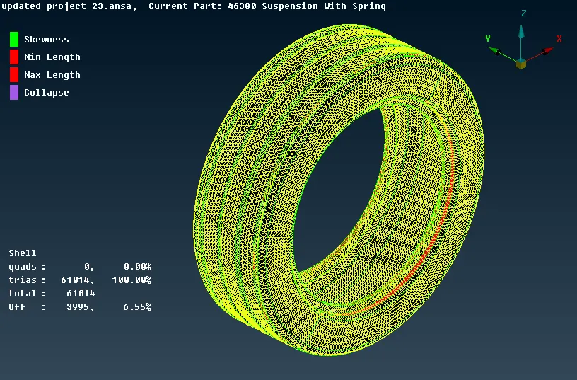
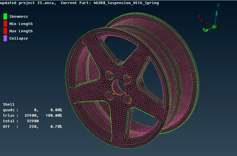
A structured mesh is defined as a mesh where the inner nodes have the same number of elements around them. Another possible interpretation of a structured mesh is that it follows a given topological pattern that is reproduced in all directions of space. Here, Ortho Tria mesh is applied on the curved surfaces and Tria mesh is applied for the plane surfaces as per the quality criteria. For this model tria, Ortho tria, and mixed element are used based on the quality criteria. There are a few off - elements present in some parts because of the small area and the intersection of neighboring nodes.
1). TYRE:
2). RIM
3). AXLE_MOUNT:
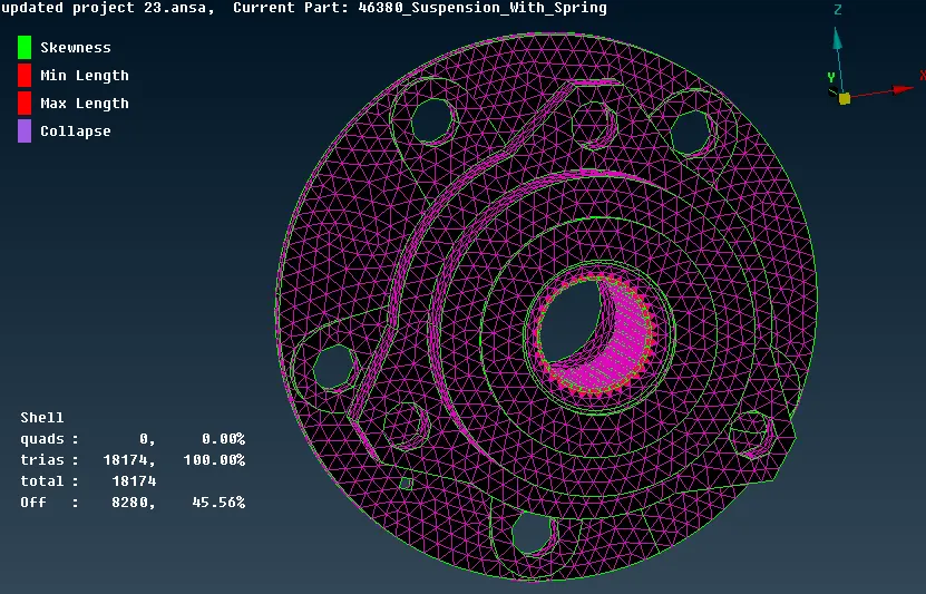
4). BALL_JOINT:
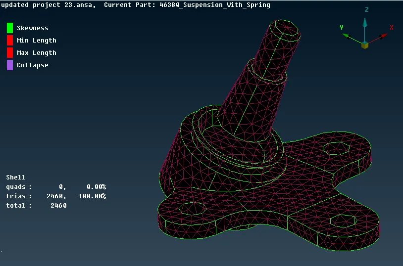
5). DISC:
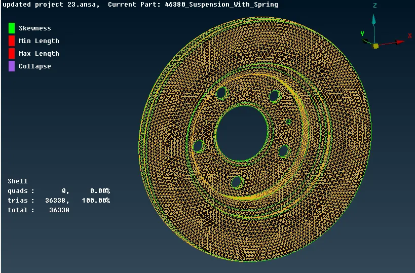
6). KNUCKLE:
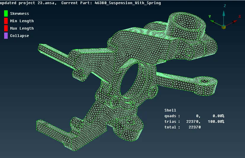
7). KNUCKLE_MOUNT:
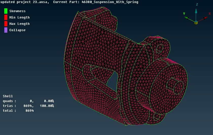
8). L_JOINT:
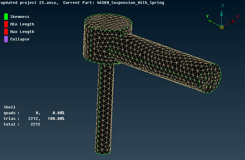
9). BASE_SUPPORT:
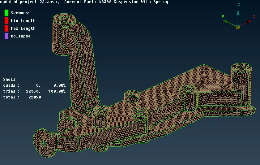
10). BRACKET:
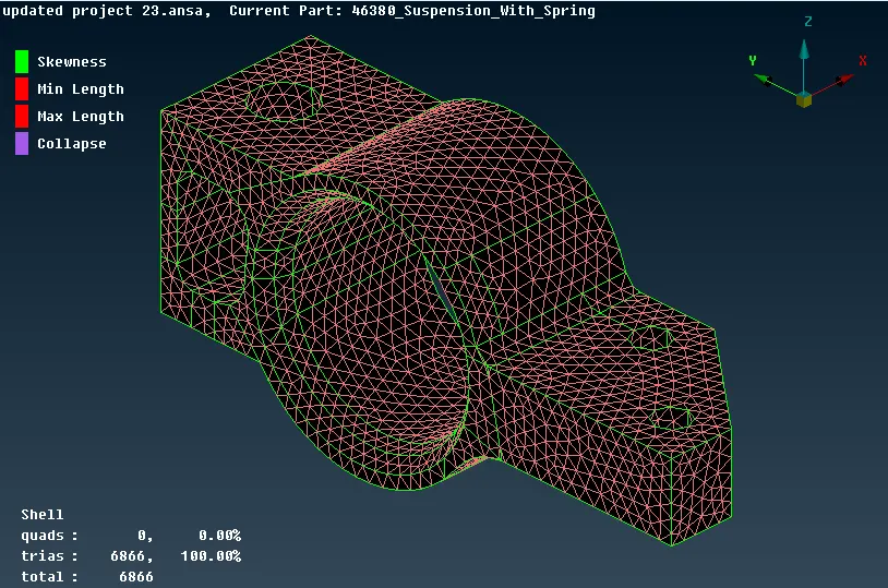
11). BUSH:
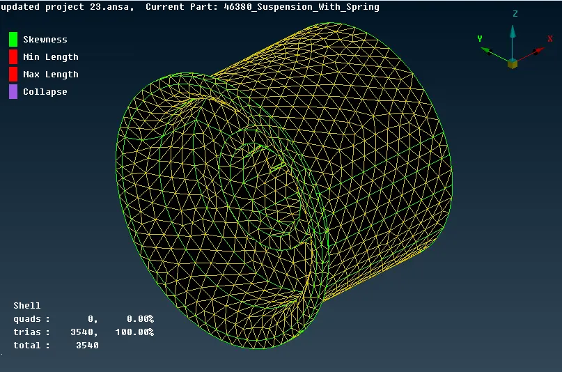
12). SWAY_BAR_LINK:
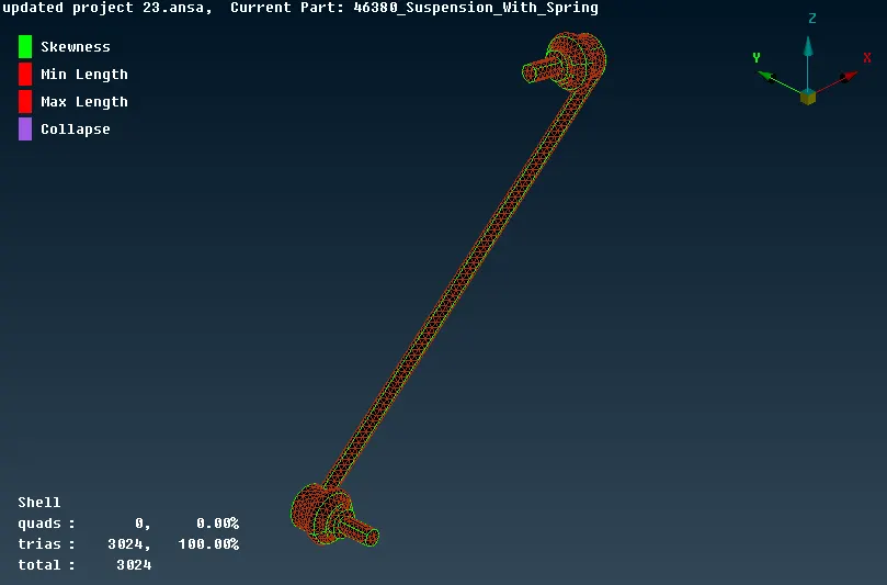
13). SWAY_BAR:
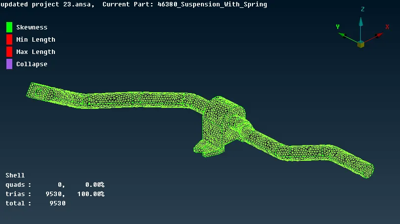
14). TRACK_BAR:
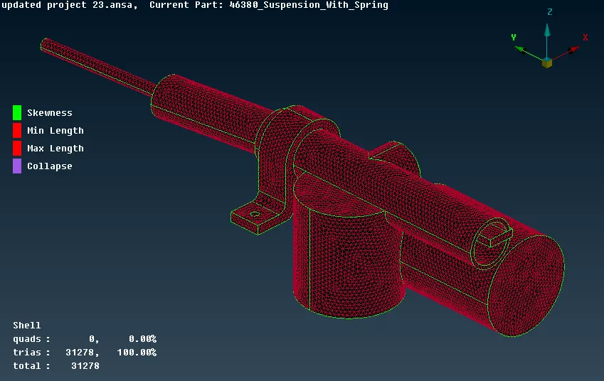
15). STRUT:
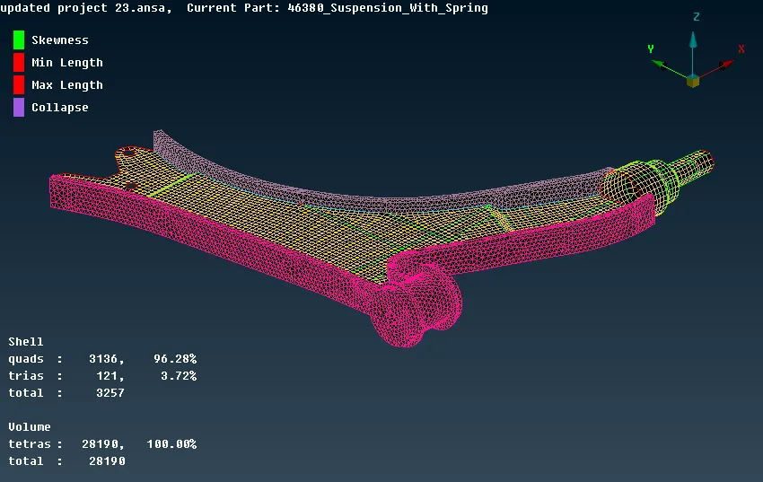
16). SHOCK_BOTTOM_CYL:
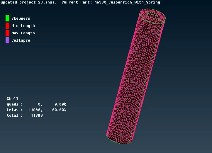
17). SHOCK_MOV_BAR:
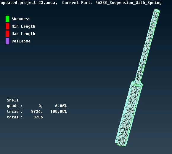
18). SHOCK_MOUNT:
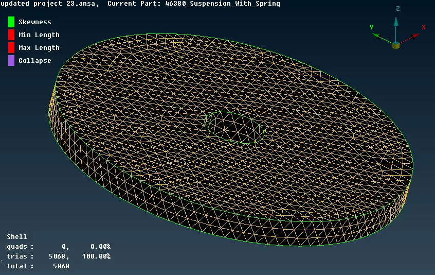
19). SHOCK_PRT:
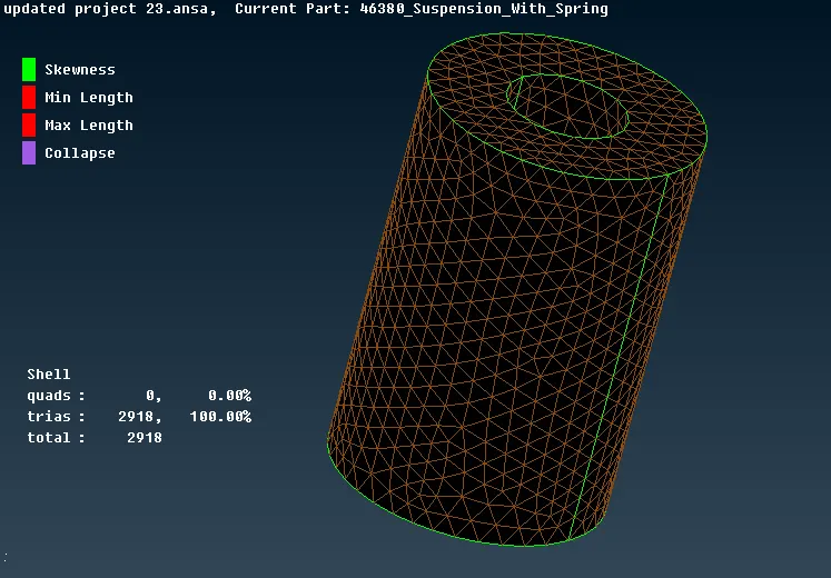
20). SHOCK_TOP_MOUNT:
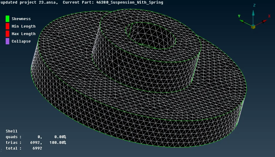
( ii ) Unstructured Mesh:
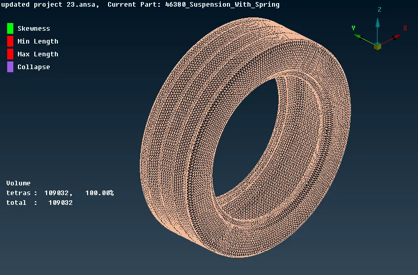
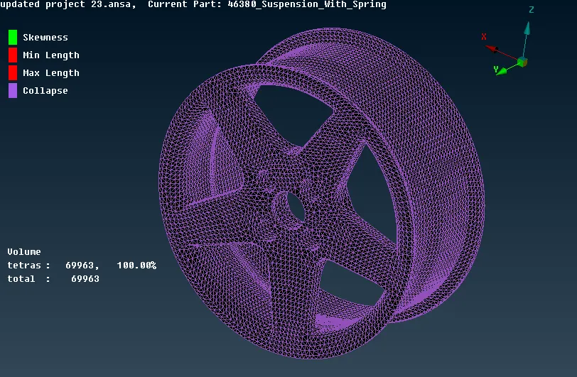
Unstructured meshes are meshes with general connectivity (GCON) whose structure is arbitrary and therefore the connectivity of elements must be defined and stored. GCON element types are non-orthogonal, such as triangles (2D) and tetrahedra (3D). There are certain types in volume mesh-like Tetra rapid, Tetra FEM, Tetra CFD, etc., The Tetra Rapid algorithm gives tetrahedral mesh (and pyramid elements, if the surface mesh contains quad elements). It is most suited for geometries of thick volumes or large domains with significant variation in the length of the surface mesh (say more than 2 orders of magnitude). Such geometries are mainly found in CFD applications. Here, Tetra rapid is applied throughout the volume and there is no teat collapse present in the model and also there is no kinks & dips on the surface.
1). TYRE:
2). RIM:
3). AXLE_JOINT:
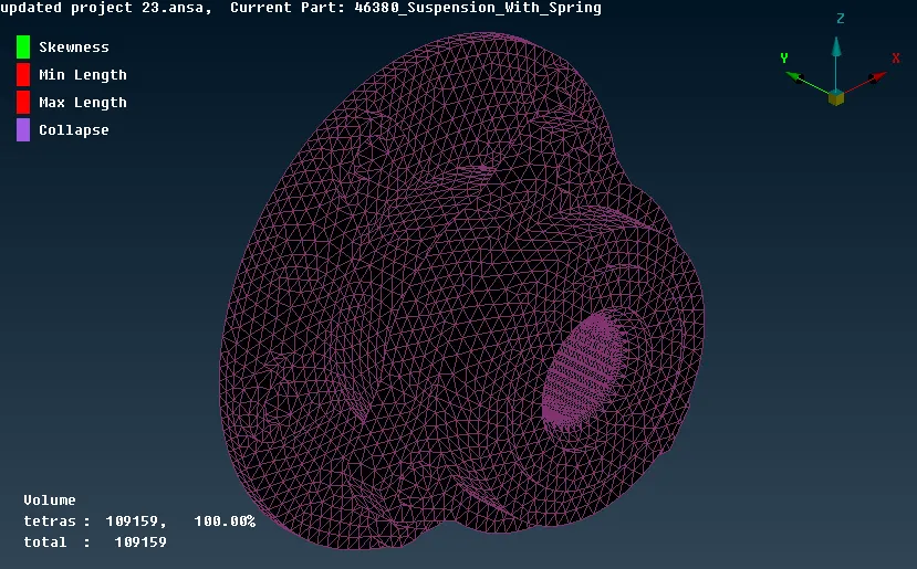
4). BALL_JOINT:
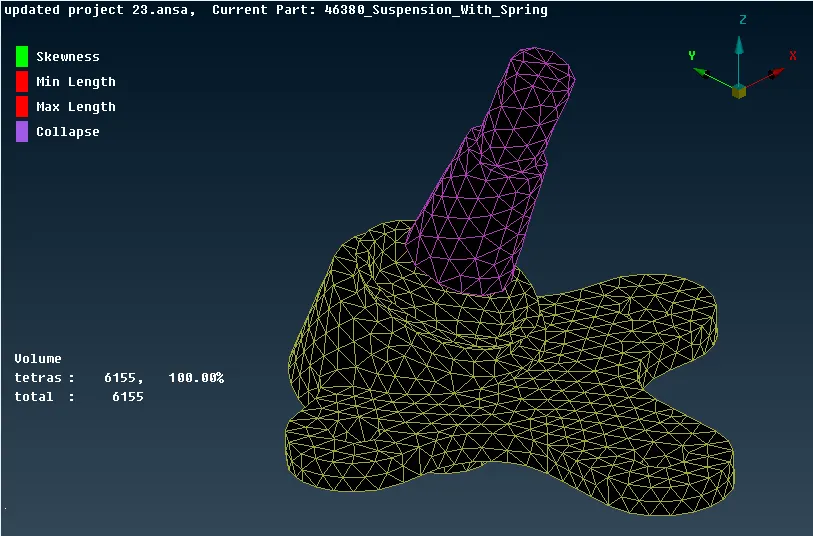
5). BASE_SUPPORT:
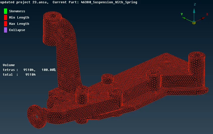
6). DISC:
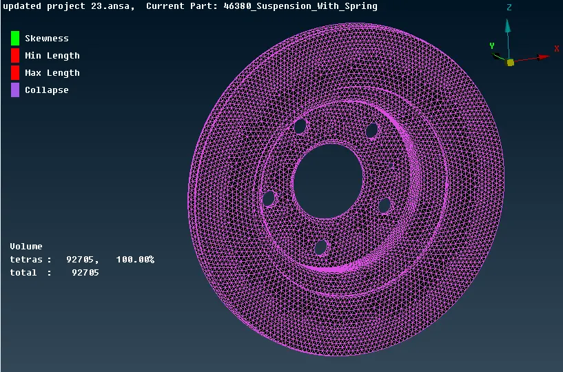
7). BRACKET:
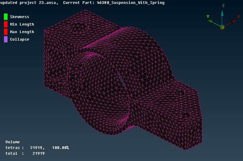
8). BUSH:
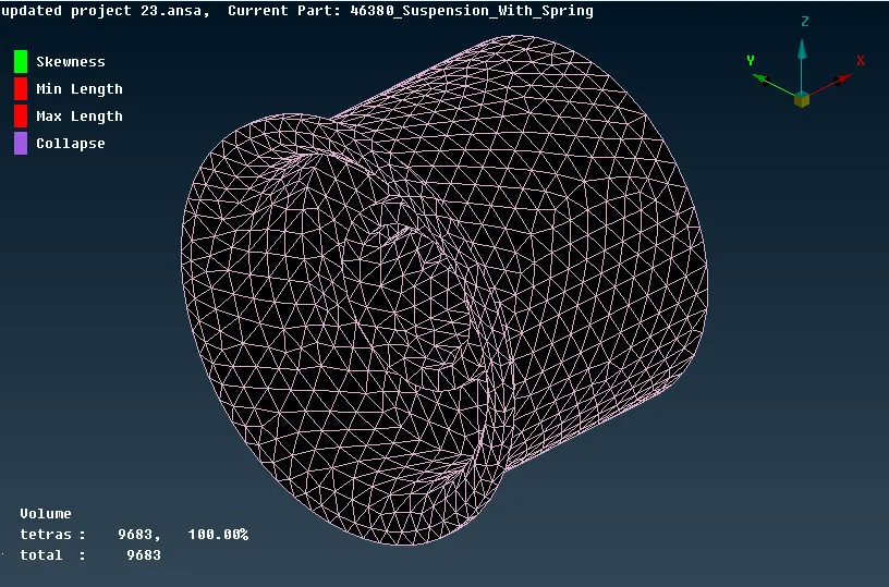
9). KNUCKLE:
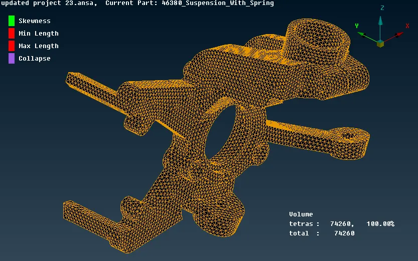
10). KNUCKLE_MOUNT:
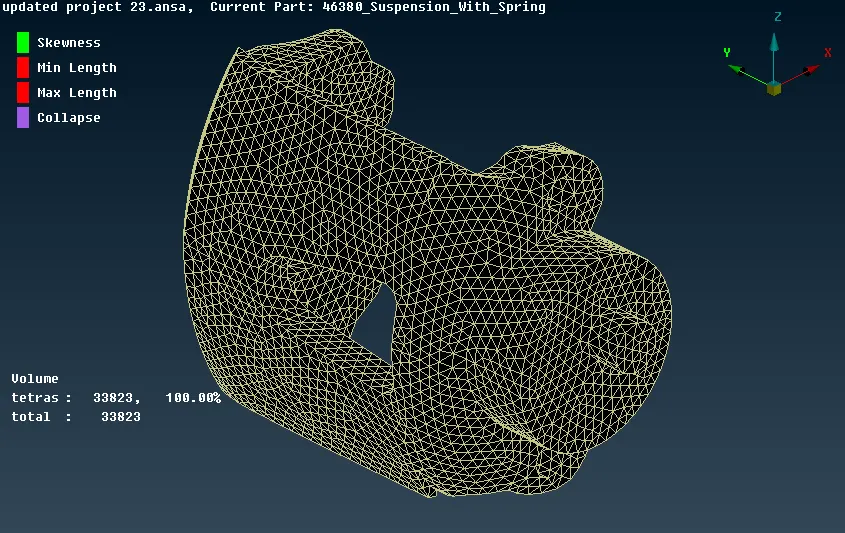
11). L-JOINT:
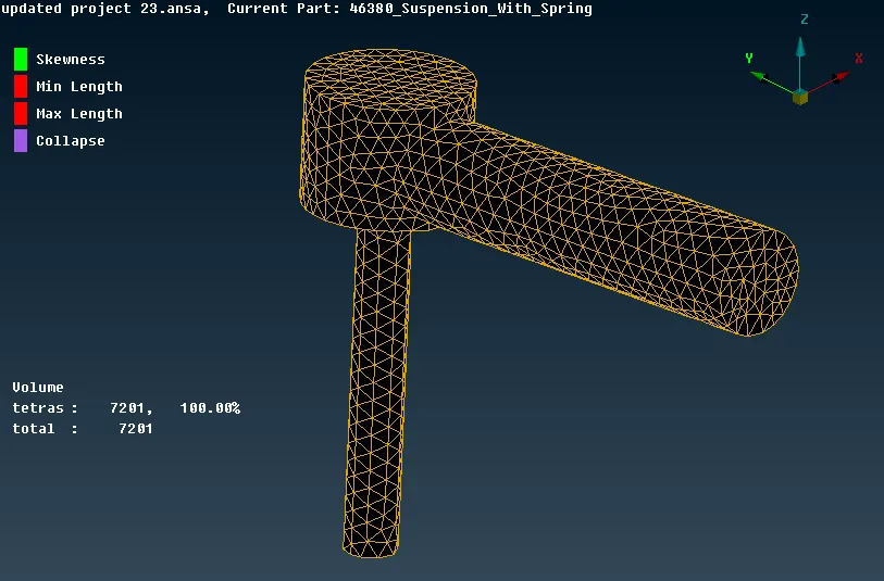
12). SWAY_BAR_LINK:
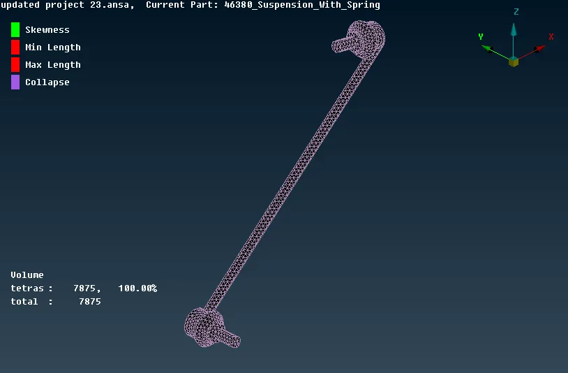
13). SWAY_BAR:
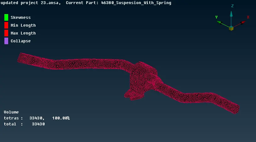
14). TRACK_BAR:
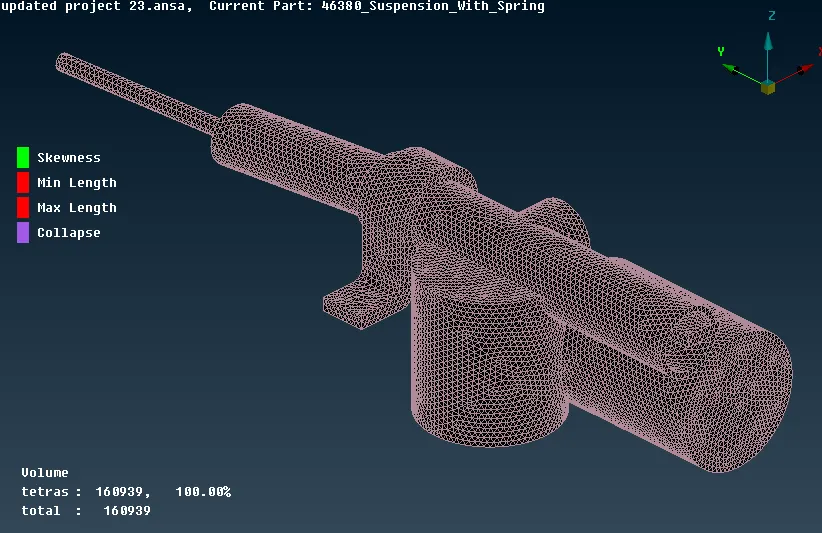
15). SHOCK_BOTTOM_CYL:
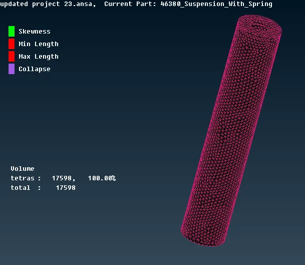
16). SHOCK_MOV_BAR:
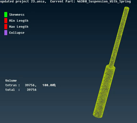
17). SHOCK_PRT:
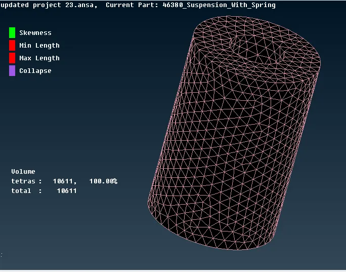
18). SHOCK_MOUNT:
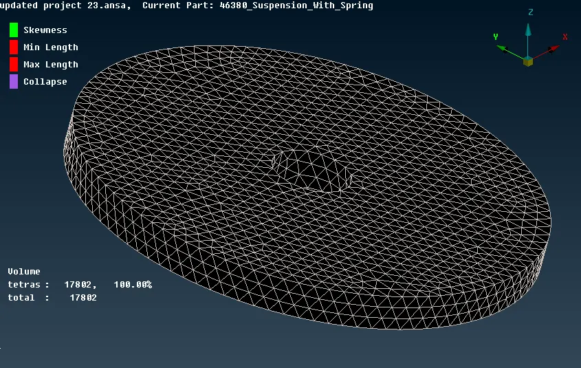
19). SHOCK_TOP_MOUNT:
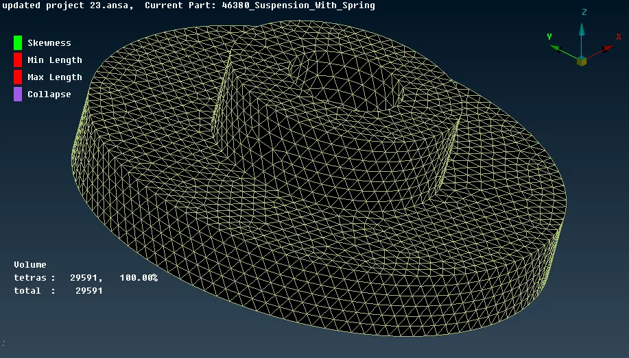
20). STRUT:
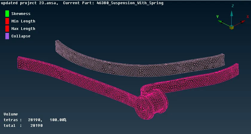
( IV) CONNECTIONS:
The way that some parts of an assembly are connected with each other can be a great factor of influence of the models’ behavior. For this reason an optimization of the connection type or pattern offers an important improvement to specific model characteristics.
Different types of connectors such as:
- Two Nodes RBE2
- Cluster RBE2
- RBE2-CBUSH-RBE2
- RBE2-HEXA-RBE2
- Nut and Bolt representation
- Seam weld data representation
Different operations such as:
- Converting and Realizing operations
- Connection Manager operations
- Assigning mass to a node
In this Rear Suspension Assemble model the connections have been done as Cluster RBE2, Two Nodes RBE2, Seam weld, and C_bar (1D).
1). Two Nodes RBE2: By selecting the 2 Master nodes of that cluster and created the two-node RBE2.
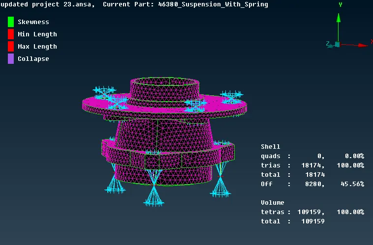
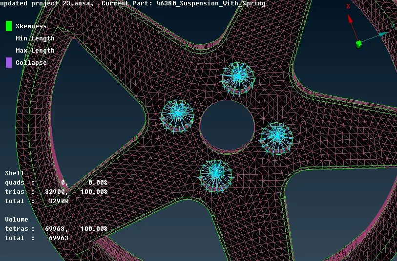
2). Cluster RBE2: By selecting the Nodes of the hole and created which shows the rigidity or Bolt connection.
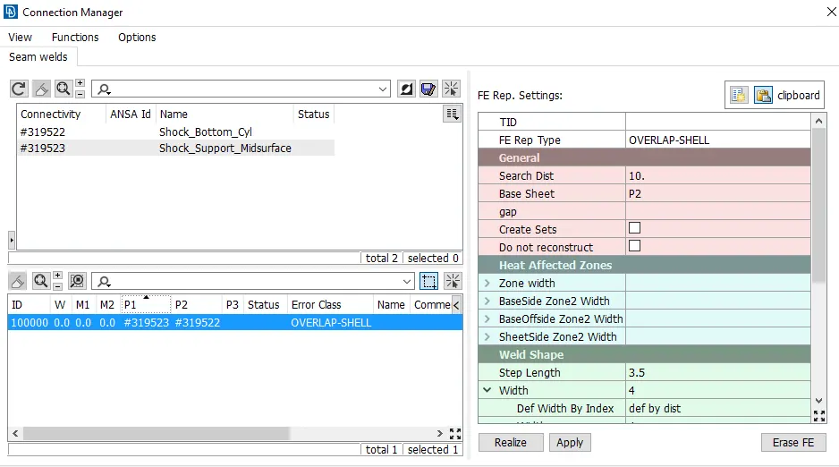
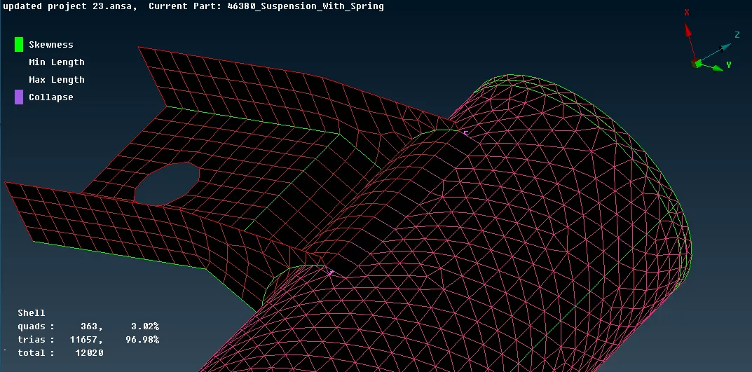
3). Seam_Weld: Initially the cons should be converted to curve and assign that curve to Seam line. By using connection manager, assign the parts to be weld and type of weld. Here, Overlap_shell as used because of parallel parts. The two parts selected as Shock_side_support (P1) and Shock_bottom_cyl (P2) which is also assigned as base part.
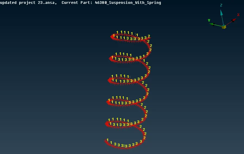
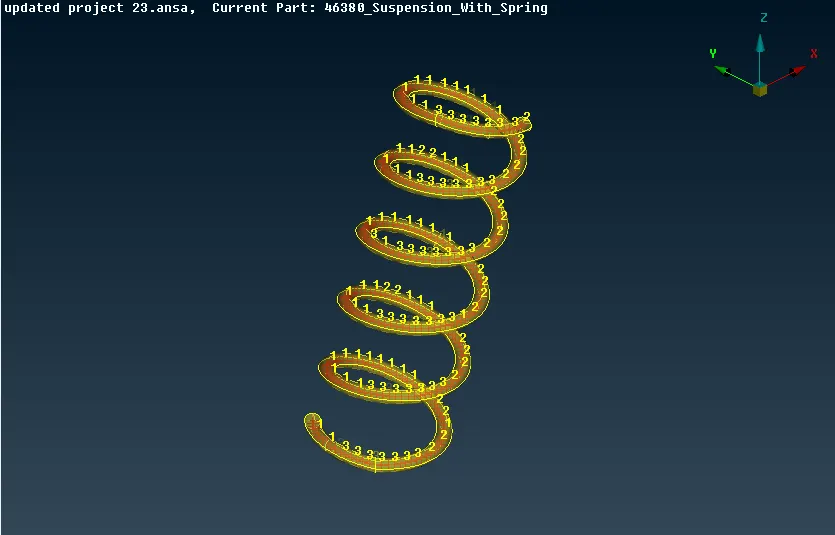
4). C_bar: By converting 2D coil spring into 1D spring, the whole surface area of the spring is taken to curve middle and assign that whole curve in C_bar and give the particular target length. In the dialog box, the radius should be assigned so that it will automatically calculate the area of the spring and when we assign the line thickness as the shell it became a 2D spring.
( V ) RESULTS:
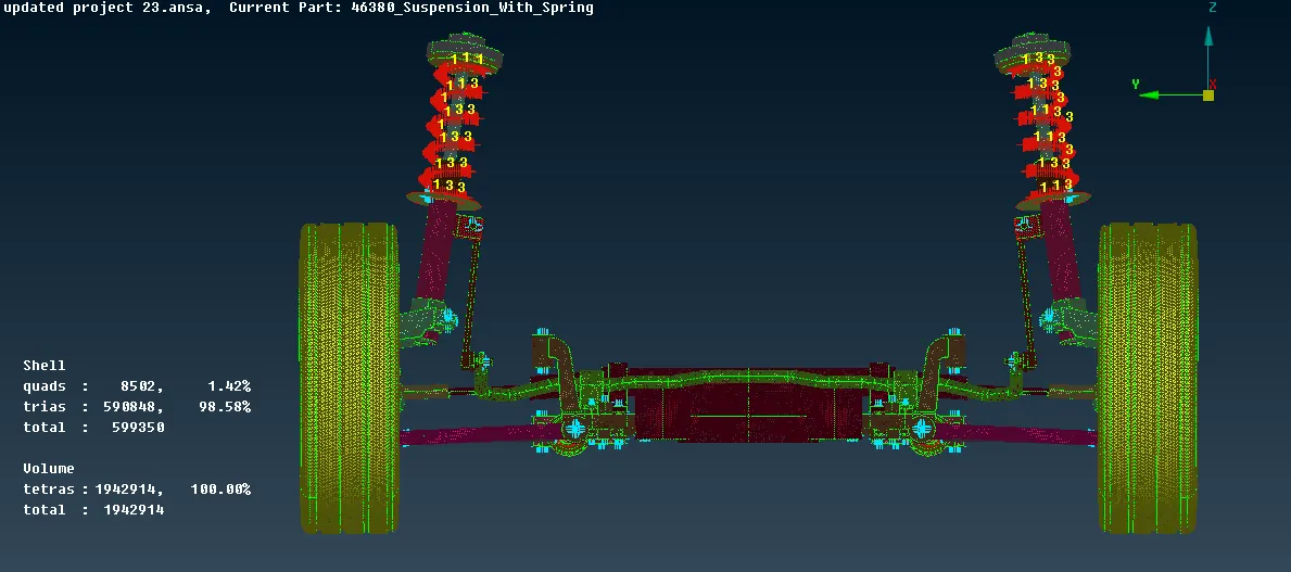
1). FRONT_VIEW:
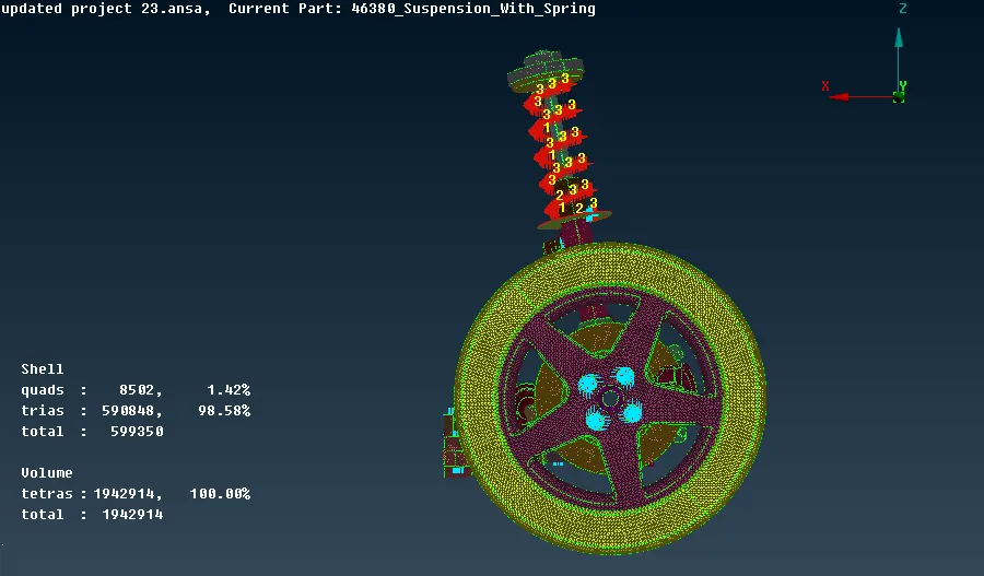
2). SIDE_VIEW:
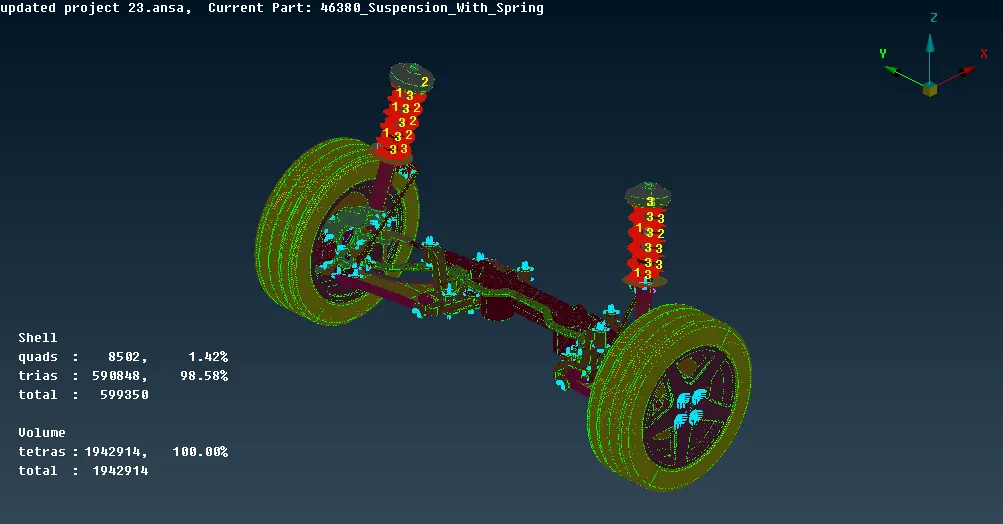
3). 3D_VIEW:
CONCLUSION:
- In the Rear Suspension Assemble model, checked for geometry clean up by part wise using PID region and created as separate Part ID.
- Meshing has been done by measuring the thickness of each part as per the quality criteria.
- If the thickness is <= 5mm, Midsurface is to be done otherwise tria mesh as to perform for that part.
- After meshing all the parts, the model was selected for symmetry and shown in the result.