Project 2
Objective:
For the given assembly, check for the geometrical errors and mesh with the given element Quality criteria. After meshing the component, the thickness must be assigned for mid surfaces. Use tetra elements to model non-uniform thickness components. Also use connections to connect the component as suggested in the Project-2 video.
Write a detailed report on your meshing process and mention which method you used to extract the mid-surface along with the reason.
Procedure:
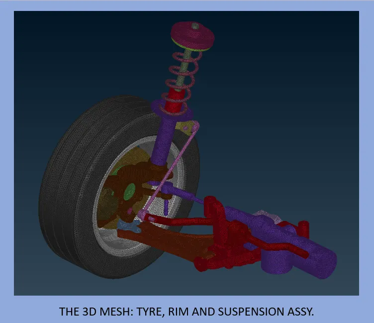
There were 3 main components:
- Tyre
- Rim
- Suspension Assembly
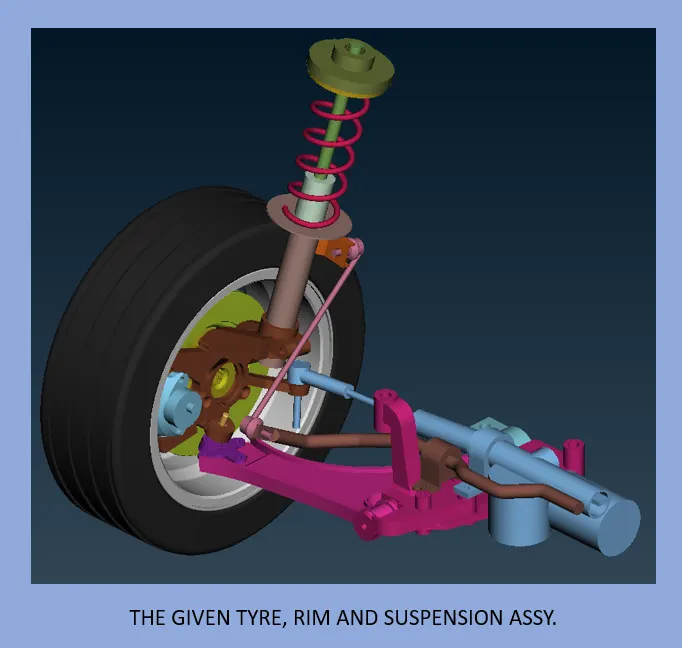
The quality criteria of Tyre and Rim are different from Suspension Assembly.
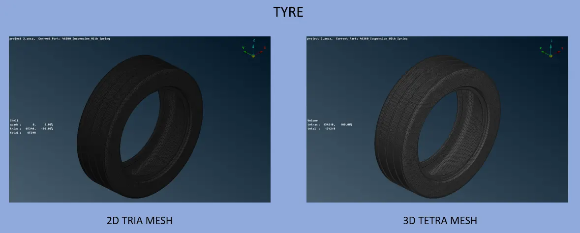
- Tyre
- Topo command was used to convert all Single CONS to Double/Triple CONS.
- The unnecessary Triple CONS were converted to Double.
- Since the target size was 6.5mm, all distances (including fillets) were maintained over 6.5mm.
- Once the geometry was corrected, spot meshing process was started.
- The spot meshing was done one-by-one on all macros using Spot Mesh Command.
- Normal tria mesh was generated.
- If the mesh generated was not satisfactory, reconstruct command was used to regenerate mesh until the mesh obtained was satisfactory.
- Once the whole part was meshed, a new volume was defined using Define command.
- The Define command helps to create a closed volume for tetra mesh generation.
- Quality parameters were assigned as per the values given in the question.
- After volume definition, Tetra Rapid command was used to generate Tetra mesh inside the newly defined Solid Volume with element size as 6.5mm.
- The solid mesh was checked for quality compliance. Collapse was under 0.2.
- This solid mesh was transferred to a separate PID.
- Rim
- Topo command was used to convert all Single CONS to Double/Triple CONS.
- The unnecessary Triple CONS were converted to Double.
- Since the target size was 6.5mm, all distances (including fillets) were maintained over 6.5mm.
- Once the geometry was corrected, spot meshing process was started.
- The spot meshing was done one-by-one on all macros using Spot Mesh Command.
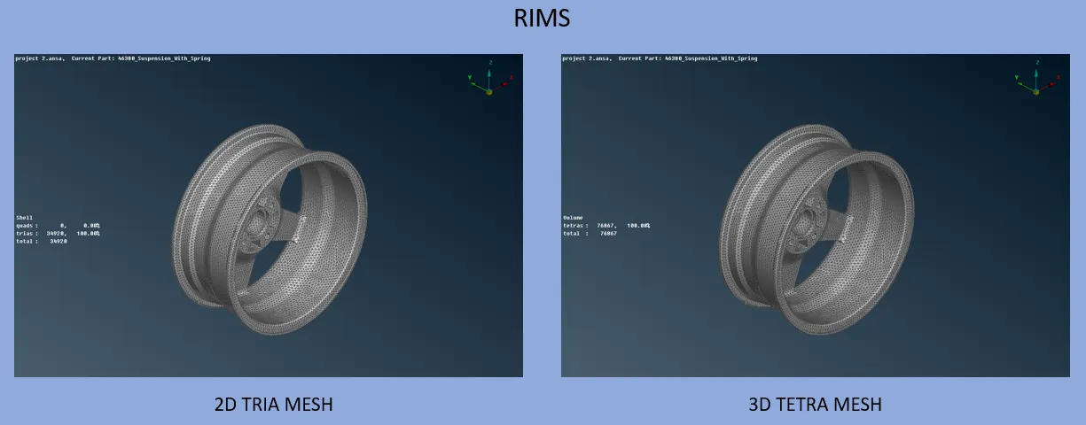
- Normal tria mesh was generated.
- If the mesh generated was not satisfactory, reconstruct command was used to regenerate mesh until the mesh obtained was satisfactory.
- Once the whole part was meshed, a new volume was defined using Define command.
- The Define command helps to create a closed volume for tetra mesh generation.
- Quality parameters were assigned as per the values given in the question.
- After volume definition, Tetra Rapid command was used to generate Tetra mesh inside the newly defined Solid Volume with element size as 6.5mm.
- The solid mesh was checked for quality compliance. Collapse was under 0.2.
- This solid mesh was transferred to a separate PID.
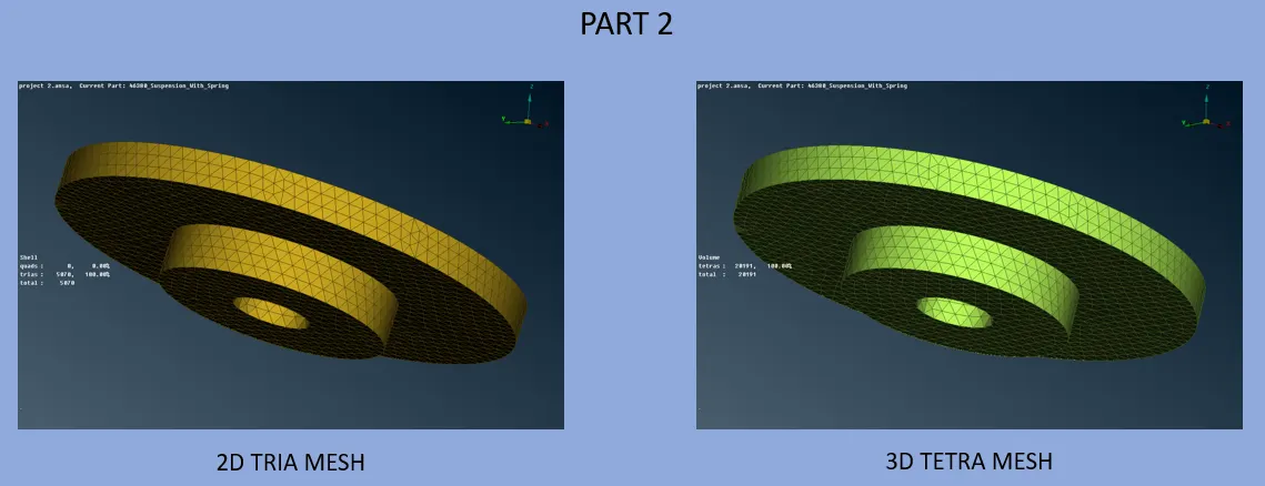
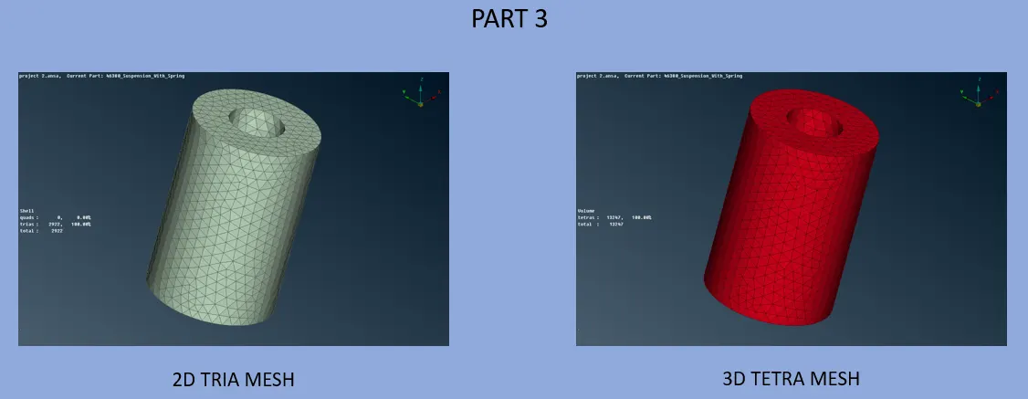
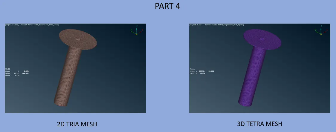
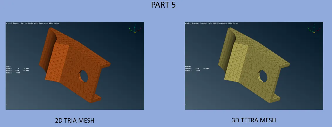
- Suspension Assembly
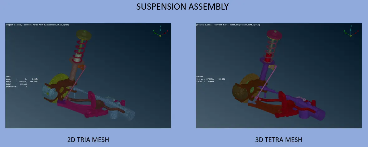
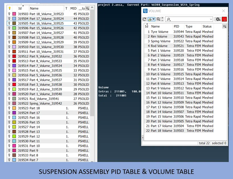
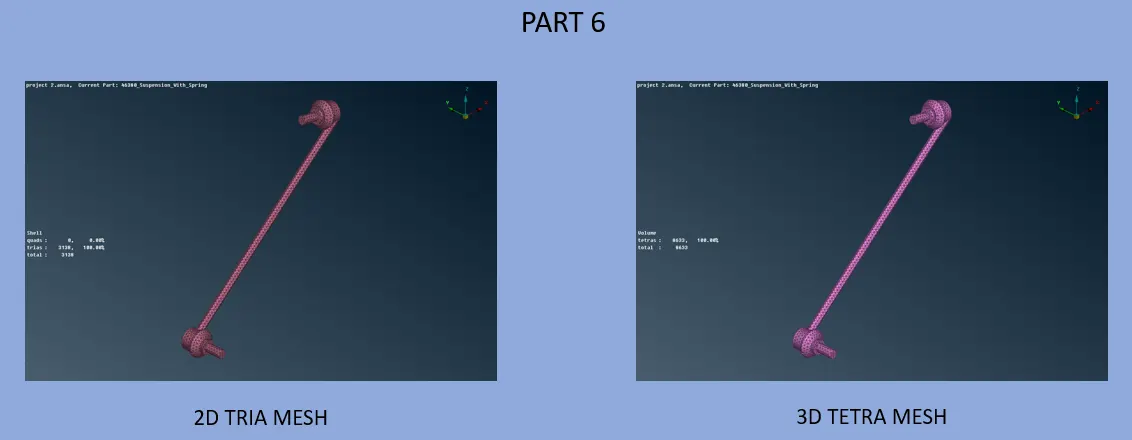
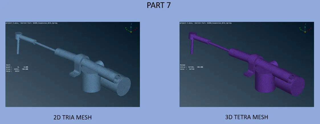
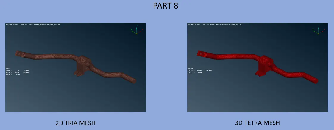
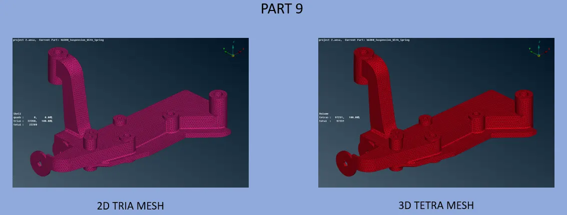
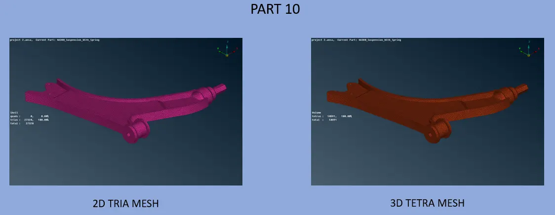
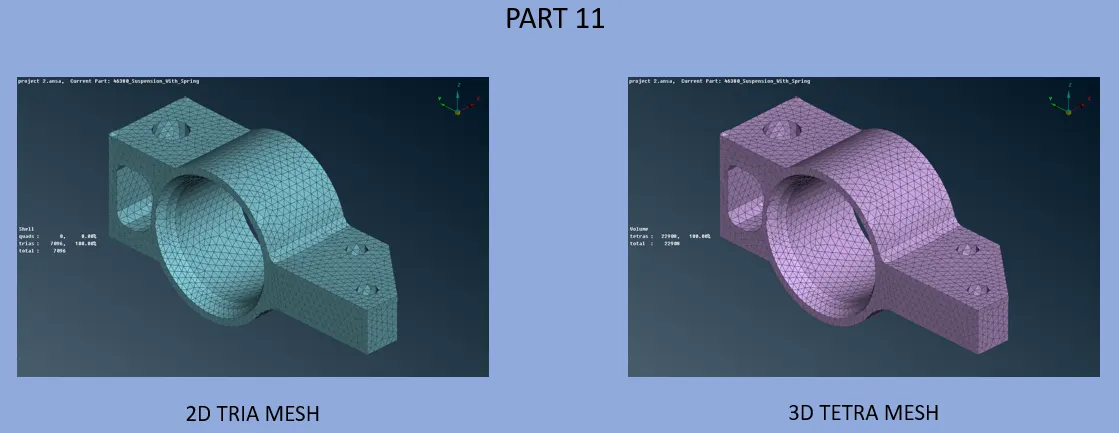
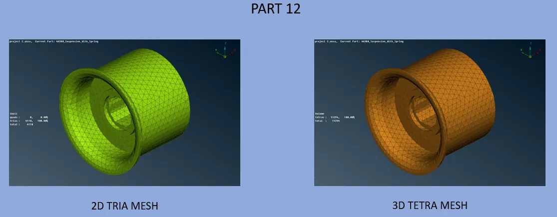
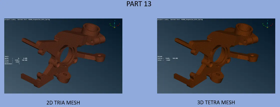
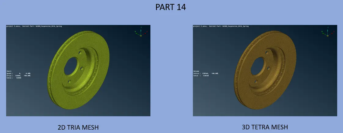
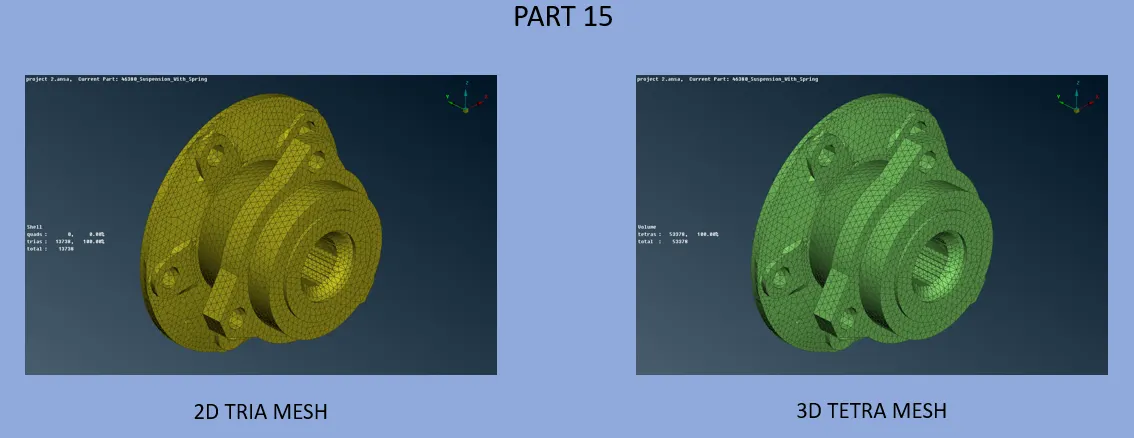
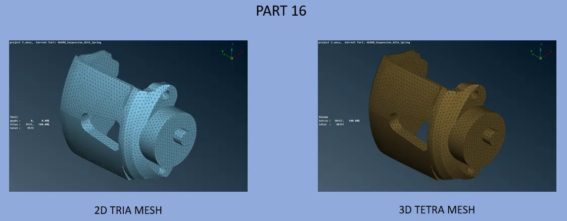
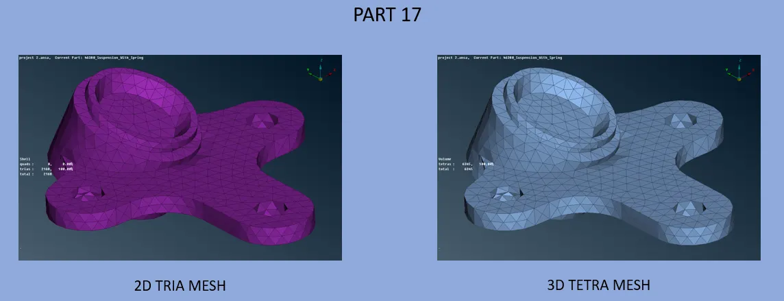
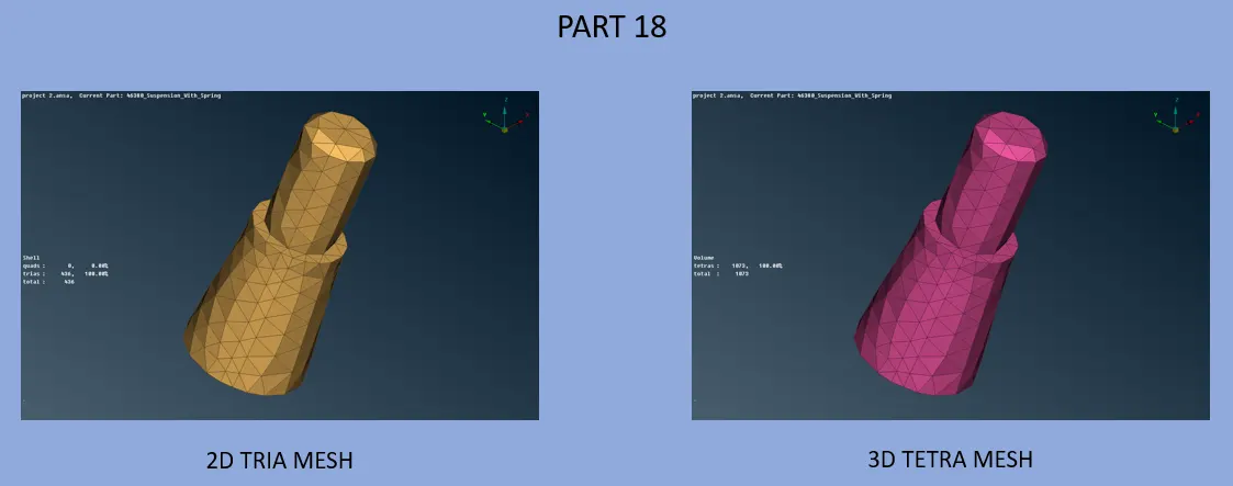
- The Suspension Assembly was a collection of 20 separate PIDs.
- Each PID region was selected and stored under an independent PID.
- Hence, the suspension assembly was split into 20 separate PIDs.
- Each PID had to be tetra meshed according to the quality criteria provided.
- The target element size was 4mm.
- For each PID the same steps as mentioned below was followed.
- Topo command was used to convert all Single CONS to Double/Triple CONS.
- The unnecessary Triple CONS were converted to Double.
- Once the geometry was corrected, spot meshing process was started.
- The spot meshing was done one-by-one on all macros using Spot Mesh Command.
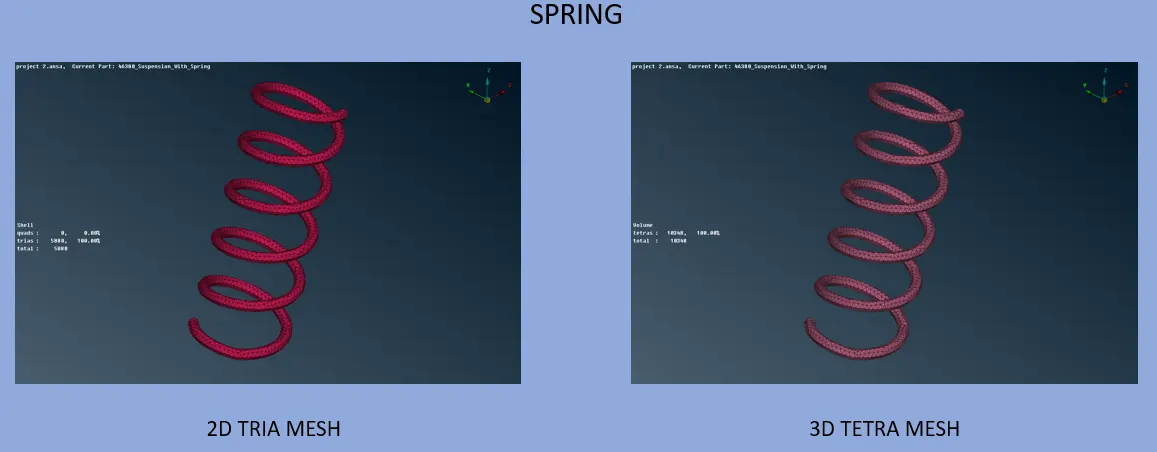
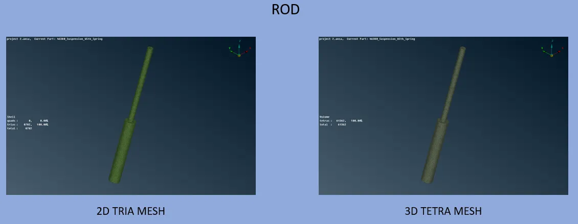
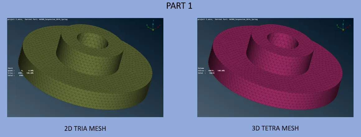
- Normal tria mesh was generated.
- If the mesh generated was not satisfactory, reconstruct command was used to regenerate mesh until the mesh obtained was satisfactory.
- Once the whole part was meshed, a new volume was defined using Define command.
- The Define command helps to create a closed volume for tetra mesh generation.
- Quality parameters were assigned as per the values given in the question.
- After volume definition, Tetra Rapid command was used to generate Tetra mesh inside the newly defined Solid Volume with element size as 4mm.
- The solid mesh was checked for quality compliance. Collapse was under 0.2.
- This solid mesh was transferred to a separate PID.
Learning Outcome:
This challenge has helped me understand how to perform 3D meshing on complex geometries. I learned the approach that must be taken in order to receive a good quality 3D mesh for large components.
Conclusion:
The given Tyre, Rim and Suspension Assembly were meshed as per the specified quality criteria.