Complete Meshing of Chassis Assembly and integration of parts using connectors in ANSA
AIM
3D mesh the chassis and suspension assembly using tetra elements and integrate the parts using the proper connections
OBJECTIVE
The suspension system is basicaly the series of parts which support the vehicle as it moves on the road. These are components which give your vehicle the ability to make turns as you rotate the steering wheel and to absorb shocks when you drive over bumps or potholes.Suspension assembly consists of tyre,rim,steering knucle,hub,wheel bearing,ball joint,wishbone,swaybar,coupling rod,tie rod etc..Each parts we need to mesh it individually and then assign differant properties to it and then we need to assemble every parts with the proper connections.Since the geometries of the components are so complex we cannot do the hexa meshing so instead we are tetrameshing the components.Some geometries can be meshed with the 2 D meshing method since the thickness of the components are below 5 mm so we can extract the midsurface first and then we can mesh it and we can assign the proper thickness to the mesh quality criteria of the componenets are given below.For the tera elements we need to ensure the tet collapse is more than 0.2.
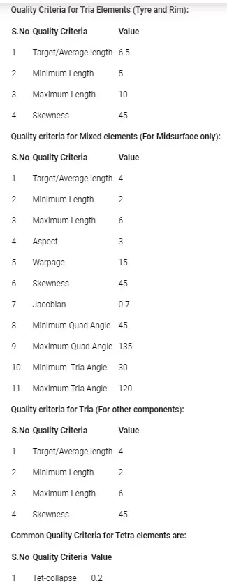
There are two differant popular susupension types.thy are mcpherson type and double wishbone type.here we are deling with the meshing and connection of a mcpherson type of suspension system.
BASIC COMPONENTS AND ITS FUNCTIONS
TYRES
Tires aren't always considered part of the suspension, but they are arguably the most important component of it. Tires provide traction for acceleration, braking, and cornering, and they absorb small bumps.Tires wear over time, and are subject to cuts and punctures from hitting sharp objects, and to slow or sudden leaks from impacts. On the other hand, wheels fail (from bending or cracking) much less often, usually only in response to hard impacts from accidents or hitting potholes.Tyres make the passengers comfort while riding or travelling in car.Now a days the non pneumatic tyres with spokes assembly are manufactured which will increase the efficiency of the suspension by adding the spring action to the coil spring.
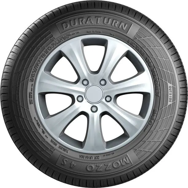
Fig 1.1 Tyre with rim
COIL SPRING
Coil springs are commonly used in vehicle suspension. Automobile suspension springs are compression springs and can differ greatly in strength and in size depending on application. A coil spring suspension can be stiff to soft depending on the vehicle it is used on. Coil spring can be either mounted with a shock absorber strut assembly or mounted separately. Coil springs in large heavy trucks allow them to ride smoothly when unloaded and once loaded the spring compresses and becomes stiff. This allows the vehicle to bounce less when loaded. Coil spring suspension is also used high performance cars so that the car can absorb bumps and have low body roll. In off-road vehicles they are used because of their range of travel they allow at the wheel.A strut assembly is there and we are inserting the metal coil spring into that.And a damper is also attached below the strut so that the energy released by the spring will be dampened by the damper only the rest small amount of energy only be exerted on to the automotive cabin. Struts assembly is filled with a thick oil, and over time the oil can leak out, causing the shock or strut to fail. Impacts and accidents can also cause leakage or can damage delicate internal parts.
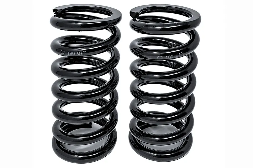
Fig 1.2 Suspension Coil Springs
KNUCKLE
Basically the knuckle is consists of provisions for the attachment of brake caliper , wheel hub and drum , wishbone and the strut asssembly. The brake caliper is attached with the knuckle to fit in the brake properly with the brake drum.Wishbone is connected with the knuckle via a ball joint.This helps in transition of the motion of the steering to the wheels.Even slight damage of the steering knuckle can affect the proper wheel alignment and disturb the stability of the vehicle. Therefore this component should be manufactured with high precision and durability.
Fig 1.3 Steering Knuckle
ANTI ROLL BAR / SWAYBAR
This is a bar which prevent the body rolling of the vehicle.In a strut mcpherson suspension system, when the vehicle moves round a corner ,the outer wheels tries to pick up and the other wheel will tries to moves down .This results in a body rolling an it is dangerous .This will be avioided by the swaybar, because the sway bar helps in even out this issue.Swaybar acts like a torsion beam.This connects with the suspension system at the both ends.Swaybar is attached with the coupler rod of the suspension system on both sides.
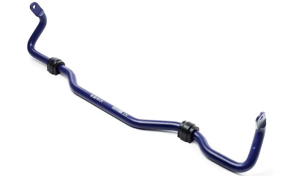
Fig 1.4 Anti Roll Bar /Swaybar
Control arm
Control Arm is the part where the suspension is attached to the subframe connection of two wheels.It is connected to the subframe with a bushing so that when the vehicle falls into a pothole ,this helps in independant movement of the suspension on each sides .this means when one side wheel is fallen into a pothole,the suspension over ther only moves up and down so that the other wheels will stays in posistion and that will eliminate some sort of problems in traveling comfort.this is why these suspensions are called independant suspensions.The bushing in this control arm also has has the function to absorb the vibrations which may remain even after the coil spring had done its job.So some little vibrations also gets absorbed by the wishbone bushings.
STRUT ASSEMBLY
The suspension strut is a damping mechanism basically acts as a shock absorber that provides structural support by carrying the weight of the vehicle. It is mounted inside a coil spring, combining the spring and shock absorber into one component. The strut also plays a role in the car’s alignment and steering system. Most of today’s cars are fitted with a MacPherson strut suspension. This type of strut is connected to the body of the vehicle and the hub carrier. It is normally used on the front wheels because it doesn’t take up a lot of space horizontally, unlike a double-wishbone suspension. For such a simple mechanism, it has a significant role in making a car’s ride smooth
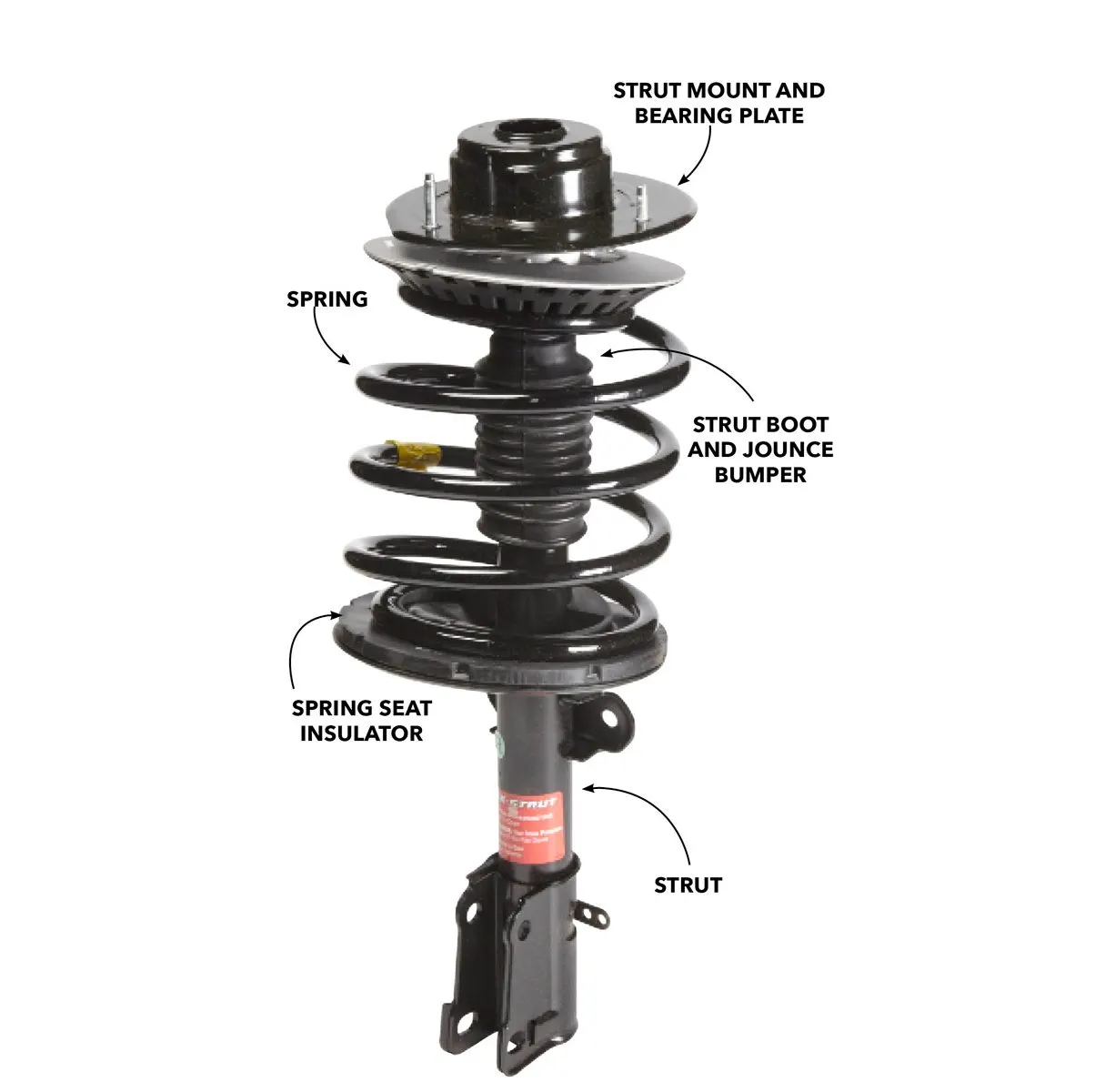
Fig 1.5 Strut Assembly
PROCEDURE
At first the model needs to be import into the ANSA.THe model is in IGS file.First open ANSA > New> Open > browse for the file > Open.This will import the model into the ANSA.
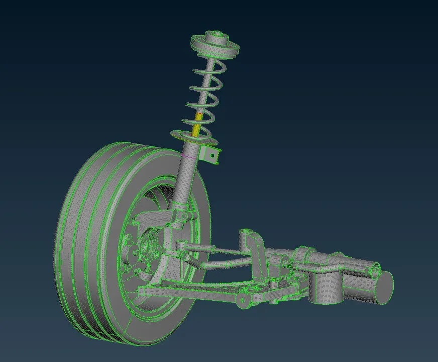
Model opened in ANSA
Topological Cleanup
When the model is entered into ANSA there will be so many CAD translational issues so we need to first do the topological clean up.Here we should first apply the TOPO on the entire model. Here in this model the CAD issues got cleared with mere topo application.This can be verified using CHECKS > geometry > select the entire model > Middle mouse click.This ensure that the CAD is not having any translational issues and so we can move on with the Tria meshing.
Setting the Length as 1 in perimeters and Macros
This is done because we needs to mesh the model with the minimum element size as 1 mm. And the refining the hotpoints at 1 mm distance from on another will helps us to see the model more accurately.This can be done by Go to Mesh Module >Length > select the enitre model > Set perimeter as 1 > OK.Similarly put the radio button in Macros and select the geometry and set the macro length to 1 mm.this will give us an idea about how the whole model looks like.
Seperating up of each individual parts
The whole suspension assemblty is consists of several parts such as tyre,rim,steering knucle,hub,wheel bearing,ball joint,wishbone,swaybar,coupling rod,tie rod etc so e need to split these individual parts and then we need to assign differant properties to it since we need to deploy connections between them at the end .
Geometrical constructions
This is done to ensure that our tria elements we are going to deploy will not be failing at the areas in the model.Inorder to ensure that we need to make some geometrical constructions in such a way that the tria elements will not fail for minimum or maximum lengths.CUT option in Topo module can be used to deploy and remove the geometric lines in such a way that the tria elements will not fail at any areas.This should be done for each and individual parts.
II) 2D Tria Meshing
Similar to the Quad meshing ,the process is similar.But we have two types of Tria elements in ANSA or any other preprocessor.They are Ortho Tria and Tria elements.Ortho is nothing but right angles tria elements and the other one is normal tria elements.The significance of the Ortho Tria is that it can be deployed in curved and complex areas to capture the features properly.Capturing feautres properly is very essential.This can be very well undergone by using the ortho tria elements.There surface capturing ability is awesome while the normal tria elements will not be capable of capturing the fillets and complex areas perfectly.So at the curved and fillet areas we will be using Ortho Tria elements.
To deploy Ortho tria elements, First go to mesh parameters and set the average length as 5.5 mm and set element type as ortho tria and press OK.Then set the quality parameters in Shell Tab as minimum length as 5 mm and maximum length as 10 mm.In the solid tab we need to set the Tet Collpase as .2.We are using this quality criteria for rim and wheel .But for the rest of the components minimum and maximum length iof the elements are 2 mm and 6 mm respectively.In ANSA it is given as Collpase only.The 3 D mesh having the tet collpase more than .4 will be the best mesh.Tet Collapse is nothing but the height of the elements.
Now we are set to proceed with the meshing process.Like what we done in shell meshing, Here we can use the SPOTMESH algorithm to deploy the TRIA elements.After the mesh deployement we can obviously use Reconstuct algorithm to reconstruct the mesh deployed.One thing we need to taken care is that the curved and fillet areas are needed to mesh with orthotria elements.But when it comes to flat areas we need to use the normal trias.This is done because the Ortho tria is computationally expensive while the normal trias are comparitavely less expensive.Once the genral 2 D meshing is done we can move on to 3D meshing.
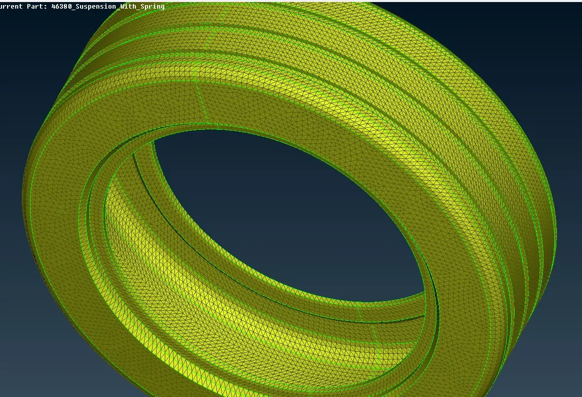
Fig 2.1 2D Meshed Tyre
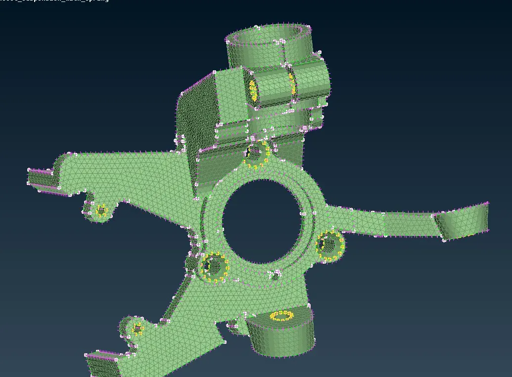
Fig 2.2 Knuckle 2D meshed
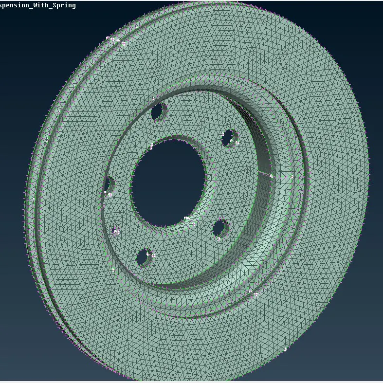
Fig 2.3 Brake drum
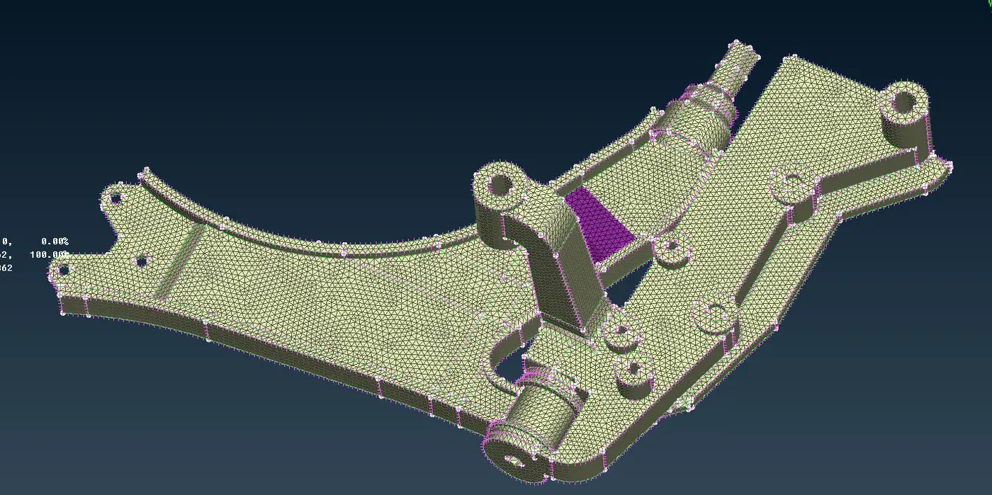
Fig 2.4 Control Arm 2 D meshed
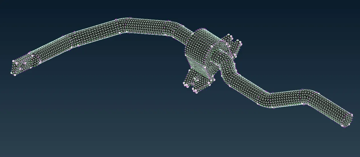
Fig 2.5 Sway Bar 2D meshed
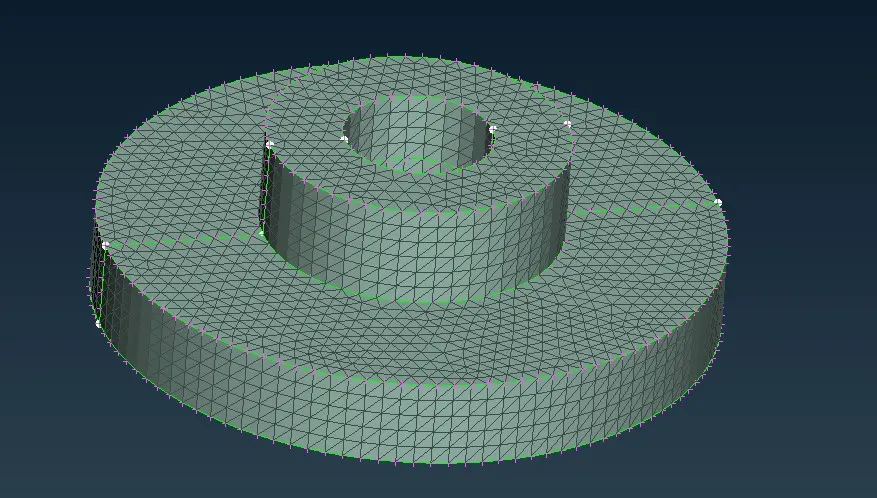
Fig 2.6 Strut Top 2 D meshed
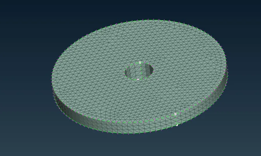
Fig 2.7 Strut Root
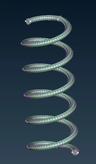
Fig 2.8 Suspension Coil Spring 2D Meshed
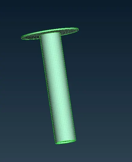
Fig 2.9 Strut and Spring Seat 2D Quad mesh
Strut and spring seat is low thickness which is of 3 mm thickness component so we can just do the midsurface and do the quad mesh on it and we can assign the thickness to the mesh at the end.
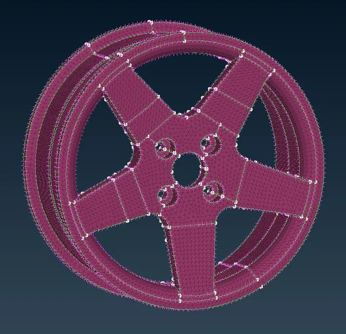
Fig 2.10 Rim 2D Meshed
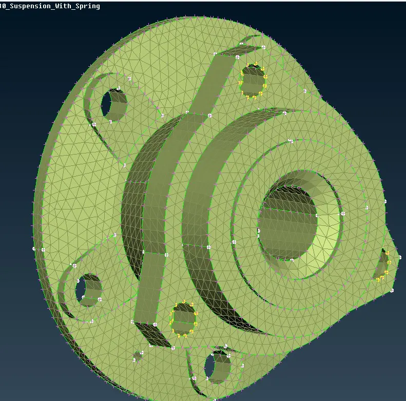
Fig 2.11 Wheel Bearing Hub 2D Meshed
After Done with the 2D meshing of all these components we need to move on to 3D meshing process.
III) 3D TetraMeshing
3D meshing is need to be done in a volume.So first what we need to done is that create a volume .We already have the model as a volume with us, but we need to define that as a volume then only the ANSA will be able to figure out it as a volume.For that in VOLUME MESH MODULE we have the define option.Select Define > Choose Manual > Select the entire model >Middle click > Right Click > New > PSOLID > GIve name and Corresponding Property Id > Ok. This will create a new volume that is recognisable by ANSA.So Then we can move onto 3 D meshing process Here in ANSA there is TETRA RAPID And TETRA FEM algorithms are avilable to create the 3D Tetramesh for structural analysis.Here we can use TETRA FEM to deploy the Tetra mesh in the volume.For that TETRA FEM >select the voliume >Middle click.This will deploys tetra mesh between the 2 D meshed surfaces.ANSA dont bother about the pattern or structure of the mesh, instead it will try to connect every tria element in one surface to every tria element in other surface.So that the mesh will be unstructured and this is predominantly due to the growth factor of the mesh.
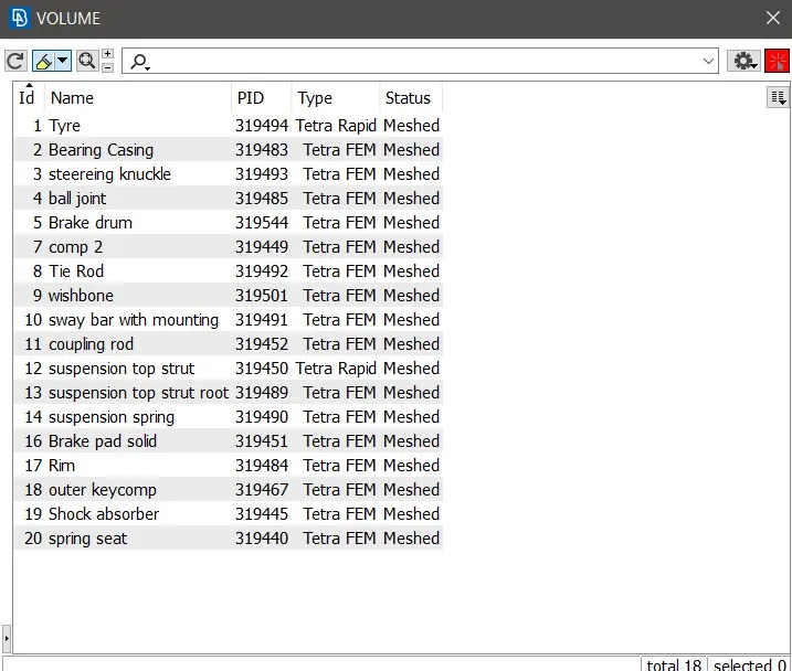
Fig 3.1 Volumes defined in the model for 3 D meshing
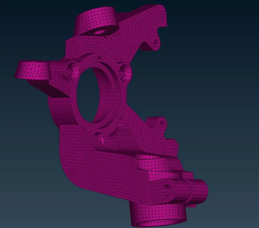
Fig 3.2 Knuckle 3D meshed
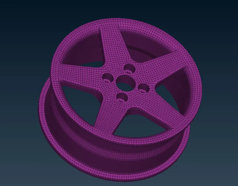
Fig 3.3 Rim 3D meshed
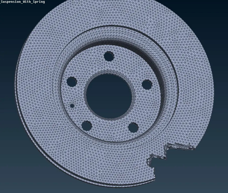
Fig 3.4 brake Drum 3D meshed with some elements masked
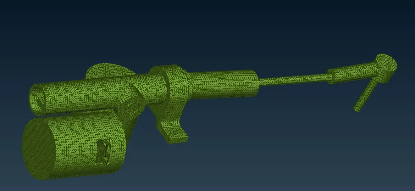
Fig 3.5 Tie rod 3D meshed with some elements masked
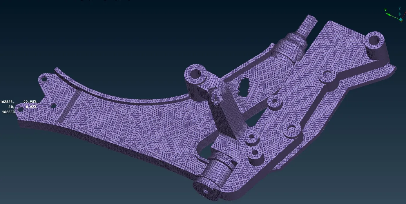
Fig 3.6 Control Arm 3D meshed
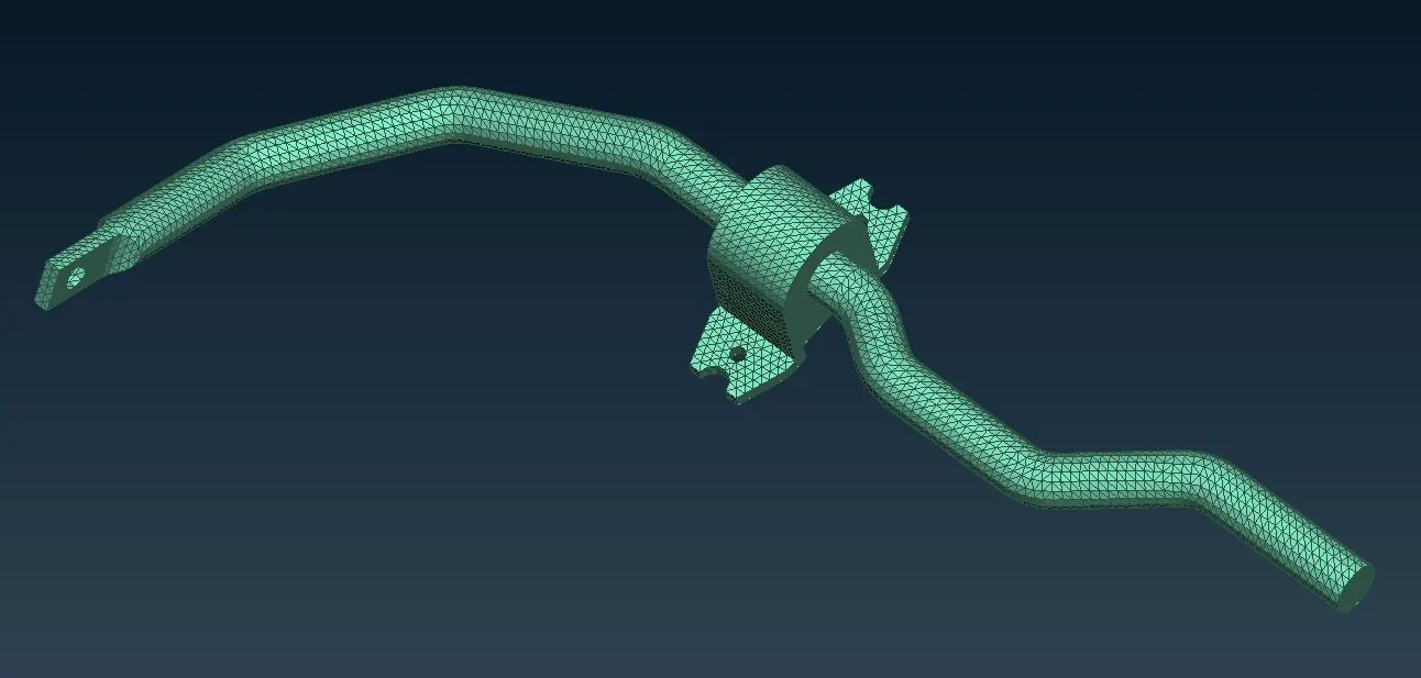
Fig 3.7 Sway Bar with mount 3D Meshed
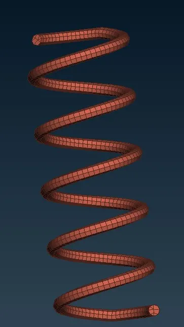
Fig 3.8 Suspension Coil Spring 3D Meshed
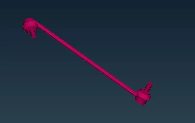
Fig 3.9 Control rod 3D Mesh
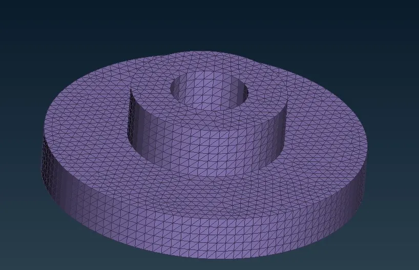
Fig 3,.10 Strut Top 3 D meshed
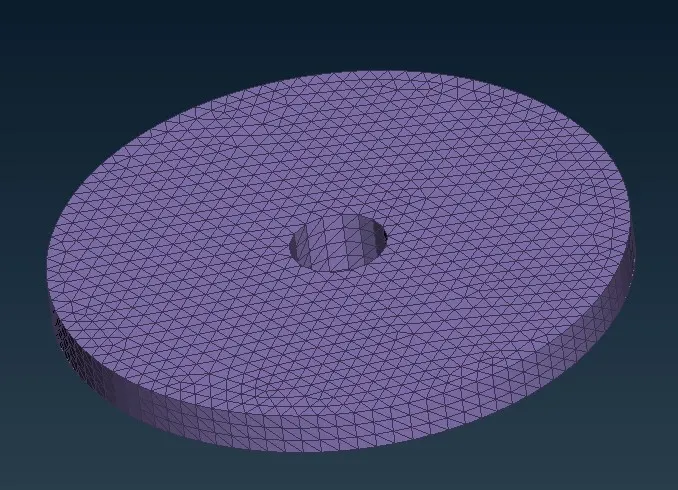
Fig 3.11 Strut root
Fig 3.12 Control Arm 3D Meshed
Then We need to move on to making connections .Here we need to consier only rigid joint between the components, we can ignore wbout the mechnaism here for now.And at the places where the bolt present,there we need to model the bolt connection using RBE2 elements. To make up this connection we need to move to the NASTRAN or any other deck module > Select the RBE2 > Many nodes >select the nodes on the parts on which we need to make our cluster RBE2 > Middle click.This can be done on the areas we need to make cluster RBE2.Thnen a master node will be created automatically considering all the selected nodes as slave nodes.
And in some areas bolt is available in the CAD itself.So in such places we use cluster RBE2 and Two node RBE2 to make the bolt connection.
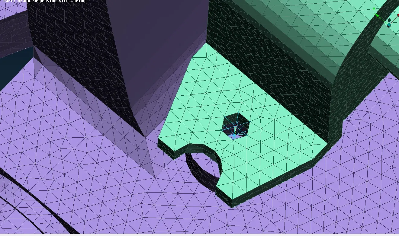
Fig 3.13 Bolt connection between swaybar mount and wishbone(using RBE2 elements)
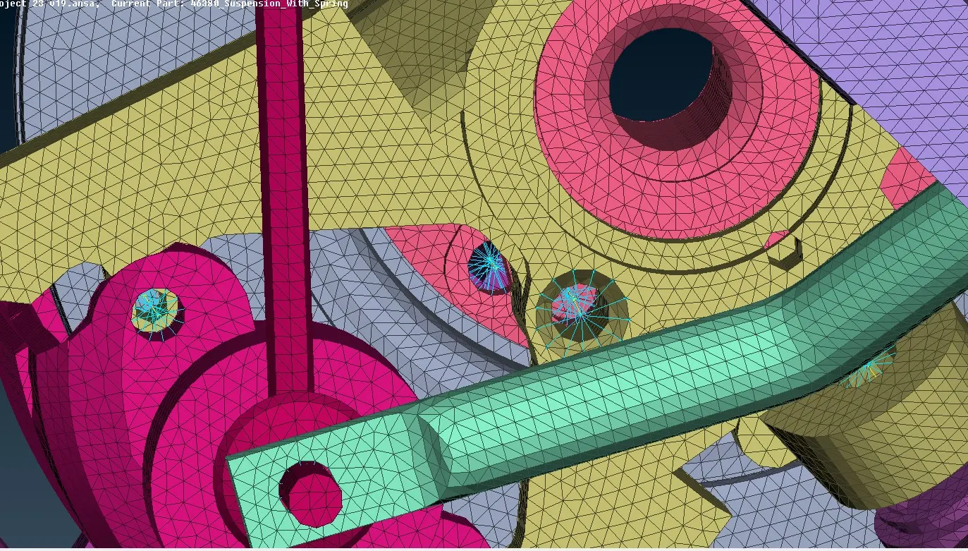
Fig 3.14 Bolt connection using RBE2 elements
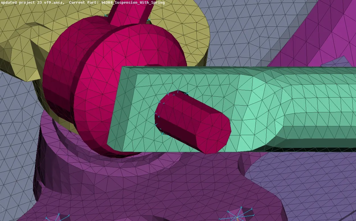
Fig 3.15 Connection between parts using cluster RBE2
Results
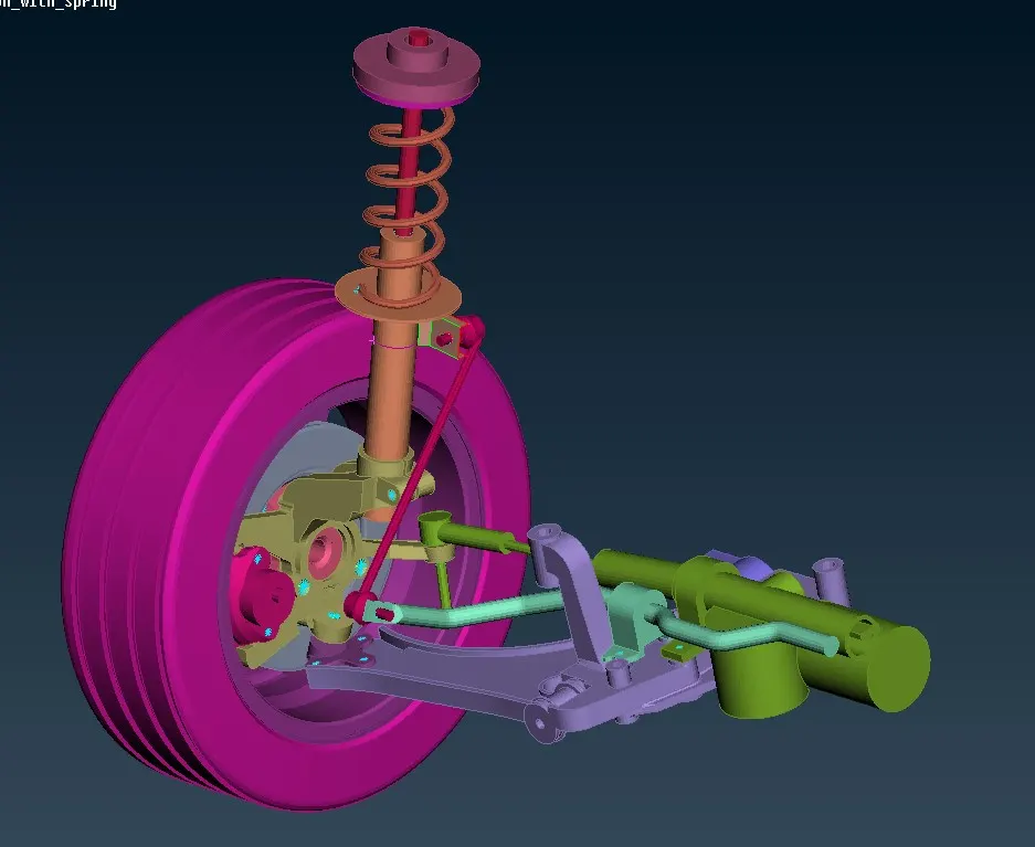
Fig 3.16 Completely 3D meshed suspension assembly integrated using Rigid RBE2 elements
Learning outcome
The method of 3D modeling the complex high thickness pats in automobile is learned and gets fair amoumnt of understanding about how to integrate the parts in an assembly for an analysis.The parts here are complex ,that is the reason why we prefer to use tetra meshing strategy here.If the model is not so complex then we will be using hexa mesh because hexa meshes tend to give more accurate values in analysis
Link for the files
https://drive.google.com/file/d/1RITkEIlrbYQoatQS2b9gZZRuB0aIaPPw/view?usp=sharing