Project 2
AIM
To route the wire harness of given car body and prepare flatten view drawing in catia V5
INTRODUCTION
A wire harness, also commonly referred to as a wiring harness, is an exterior sheath used to cover some types of electronic wires. Generally, wiring harnesses are made of thermoplastic or thermoset materials that can help protect the cables from the environment.
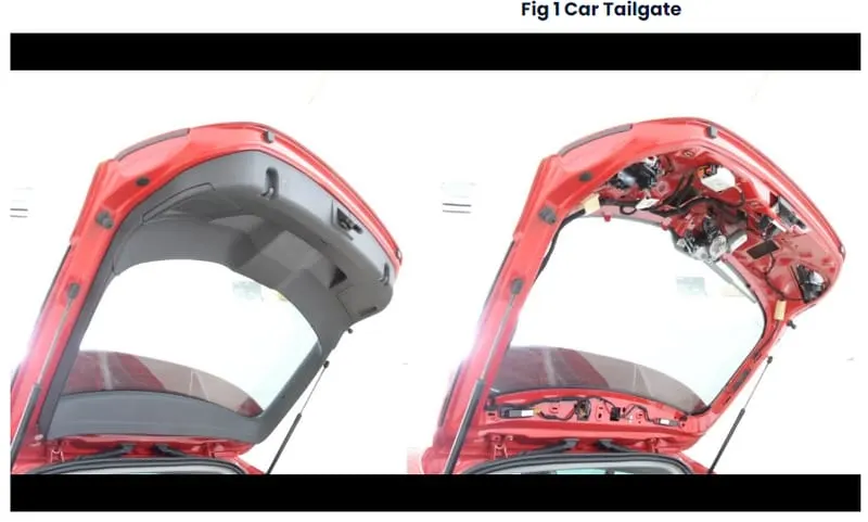
this is the images found after doing research on tailgate of the car.eventhough every car won't have similar way of routing.it differe from company to company and cars to cars
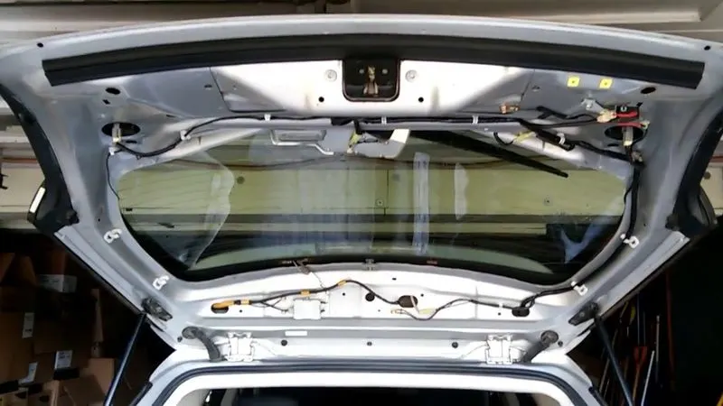
this is also a reference image used to do this project.all these images of routing in bak door of cars and both have difference in routing and components used.
wire routing in the tailgate of car is used to control tail light,rear whiper.rear camera,collision sensors and trunk open or close sensor.
OBJECTIVE
download the enigne,connector,p clamp etc cad file from given link
give required points,plane and axis in part design workbench
define the cad file electrically in electrical part design workbench
assemble them in required position for wire harness in mechanical assembly workbench
create a product file and bring engine cad file and wire harness product file
create bundle using wire harness assembly workbench
create flattening of the wire harness using harness flattening workbench
create the 2D drawing of the flattening in drawing workbench
RULES TO BE FOLLOWED DURING ROUTING
Wiring harness should be routed in such way that it is easy to assemble and access.
Easy manufacturing, installation, removal and maintenance have to be considered while designing the wire harness.
Wiring Harness should be kept away from sharp environment like edges, corners etc.
Avoid harness routing and clipping in the blind zones or hard to reach areas during harness assembly or service.
Provide additional slack if needed according to the surrounding and harness bending requirement. If harness is passing through the closures/doors or tail gates then envelope dimensions during opening and closing of doors shall be considered to provide the slack. Check the harness slack requirements with open and close conditions to avoid excess slack.
Routing through small structural holes and openings shall be avoided. To minimize chaffing and handling of the wiring harness during installation.
It should be make sure that there is no case of fouling while designing the wiring harness in the CAD environment. Additional mounting equipments like clips/clamps may be used to avoid fouling.
Use of rubber grommet is recommanded if harness is passing through sheet metal panels. Example- firewall, passing to door, tail gate etc.
The branch length should be greater than 50mm.
The minimum distance between the clip and branch point should be at least 25mm.
The minimum distance between the two branch points should be at least 50mm.
Clips/clamps used for the wiring harness should be easily available in the market to avoid extra cost for custom mounting solutions.
PROCEDURE
step 1
first download the cad files from the link given.given neccessary point and axis to define each object in part design workbench.here we have connector,channel,p clamp,fir tree clip and connector clip.each object is given seperate things to define electrically.
for connector - point and axis is given to define connector connection point,bundle connection point and cavity connection point if there.
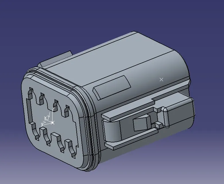
this is a 8 pole connector.point and axis are given at mating region and point is given in bundle entry region.
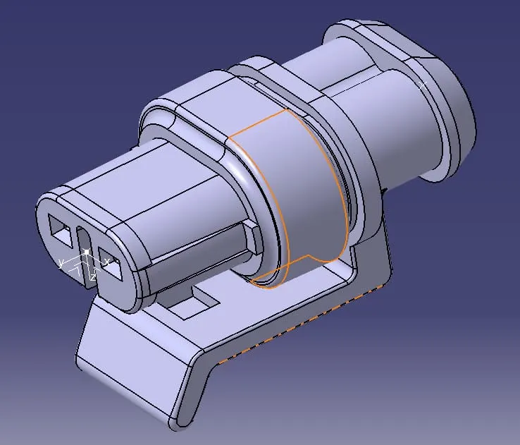
this is a 2 pole connector.point and axis are given at mating region and point is given in bundle entry region.
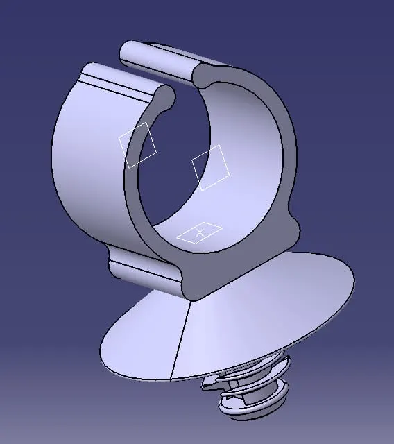
for p clamp and fir tree clip - point and plane are given to define
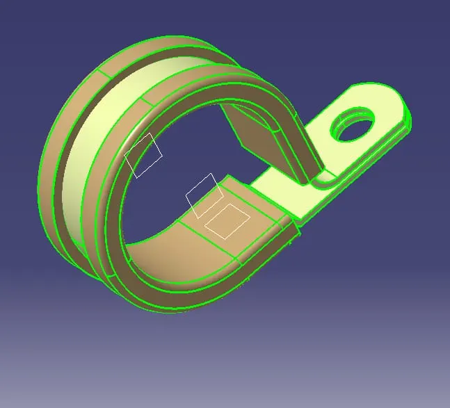
points at the centre of each side of circular arch is given and planes at each side faces and base of p vlamp is given.
 .
.
it is defined in the same way like the p clamp.point and planes are given in each side faces and other plane is given in the base of the cylindrical surface inside.
step 2
define the cad part with points,planes etc electrically using electrical part design workbench.
for connector;first define the body as connector by giving number of terminals in open window displayed when we click.

then define connector connection point by

bundle connection point by.

for p clamp and fir tree clip; define it as supporting parts by clicking

and give corresponding entry and exit planes and point.here we gave the first plane as the first entry of bundle.then point on that plane is given in point option.then we give exit plane of the bundle in second plane.then the 0 offst plane on the base is given as base plane.here we have to do the same becausethe bundle can come in both plane direction. so we select the same option and give the exit plane of previous as first palne and it's point in point tab.here second plane will be selected as entry plane in first as default.so we don't have to select them.then select the base plane as selected in previous procedure.
after defining these body parts;create COT tube in the same workbench.when we click protection part; a window popup where we have to give inner diameter and thickness for the COT tube and save it it a catalog using store device option.
step 3
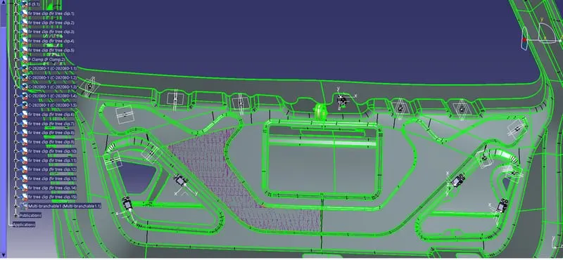
create a product file as context file and in that bring the back door cad file and create another product file in context file to create wire harness.in wire harness product file bring the required connectors and place it appropriate position on the engine.use pclamp and fur tree clip on specific postion to avoid sharp edge contact on the engine for the bundles.make sure the body parts in the wire harness except the to surface of channel; is electrically defined.
step 4
for creating bundles change the workbench from mechanical assembly to electrical wire harness.first define the wire harness product file as geometry bundles.then start creating bundles using multi branch tool.

when it's window pop up;give required diameter,bend ratio and start route defining.in that; give we can tangency direction etc while selecting start and end of bundles.
for creating sub branch;first create branch point using create branch point option.

we have to select bundle and can give point on branch on basis of lenght and ratio of point with bundle lenght.then create sub branch from the branch point to required connectors or other body.we can give slack to the bundle inorder to avoid fouling of bundle with the surface of engine.
after creating the bundles;check the bundle continuity and bundle warning.for checking bundle continuity - select edit>search option.when that window popup; click advanced then give electrical in workbench,bundle segment in type and full connected in attributes.give true for showing full connected bundle and click search.the fully connected bundle will showup.we can give false instead of true.then non continuity files will show.
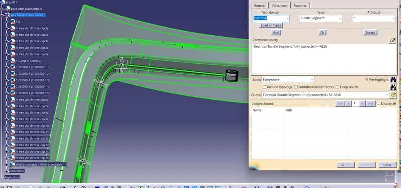
the image shown is the bundle continuity checking and it shows no discontinuity or break in bundles.
we can check bundle waring by checking any yellow warning sign like this logo ⚠ show up in any branches in multibranchable.if it show up in any branches; it will show up in multi branchables too.usually these warning happens whwn there is issue in bending radius.we should avoid these bundle warning by any mean while creating bundle.
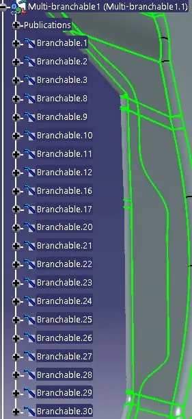
this image shows that there is no bundle warning.so no problem in bundle bend radius and other.
step 5
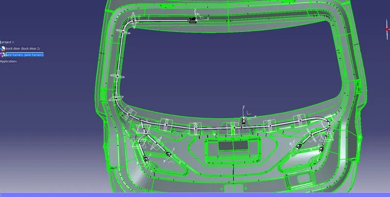
after creating bundles and checked bundle continuity and bundle warning ;create protection to the bundle from hazardous situation and environment by forming COT tubes on the bundle which is one of the protective covering used over bundles.the COT tubes are created by clicking protective covering option.before that we have to create COT tube and save them in a catlogue which is then used in future.we gave extrimity distance to free movement of bundle beacuse of protective covering.
here we have used 10mm dia COT tubes for the protection of bundles.it is showned as the grey covering over the bundles.
step 6
clearance for the bundle with respect to each surface and region is checked.the clearance value for each region like exhaust line,turbo charger,screws, sharp ends etc would be different.so clearance value is also checked for the bundle in each region.
step 7
create another product file for flattening and change workbech to electrical harness falttening.first give flattening parameters.then extract the wire harness product file into the flattenign product file.after bringing wire harness product file into the flattening product file;the name of the wire harness product in flattenign product file is changed to ehf at the end of the name.ehf stands for electrical harness flattening.then flatten the wire harness using flattening tool.then the 3D wire harness would be displayed like 2D drawing on the plane which we gave while defining flattening parameters.we can change the drawing with tools like rotate,roll,scale etc.but scale tool won't be using much.
also make sure that the flattening and wire harness file is saving in same location.
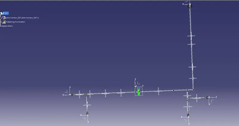
his is the flattened wire harness of this project.
step 8
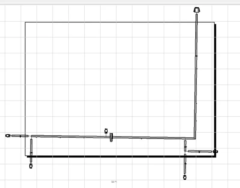
the 2D drawing of the flatten is the next procedure.for that we should first create a blank A0 sheet and bring the flattened wire harness to the drawing sheet.since the drawing is large enough.it won't fit in the A0 sheet which is maximum in catia V5.
RESULT
the wire harness for the back door of car is created by considering various packaging rules and constraints while routing the harness.wire harness's flattening is created and saved in same location.2D drawing of flattening is created and also saved in same location.