Project 2
1. Design a Warehouse Building located in Chennai using STAAD Pro Connect Edition. The specification must be as follows:
|
Width |
30m |
|
Length |
50m |
|
Eave Height |
9m |
|
Bay spacing |
6m |
|
Soil type |
Medium |
|
Safe Bearing Capacity |
200 kN/m2 |
|
Roof slope |
1 in 12 |
Assume suitable sections for structural elements. Follow IS800:2007, IS1893 and IS 875
- Prepare a Design Basis Report for the project
- Create structural model using STAAD Pro Connect Edition
- Prepare DL, LL, WL and EQL load calculations as per IS 875 standards
- Design using MS – Excel
- Steel column
- Rafter
- Base plate
- Pedestal
- Z- purlin
- Design Foundations using STAAD Foundation.
- Attach necessary sketches and drawings wherever required.
- All stipulations, assumptions and design parameter must adhere to Indian Standards
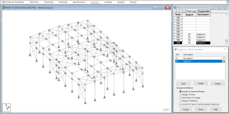
GEOMETRY / MODEL CREATION:
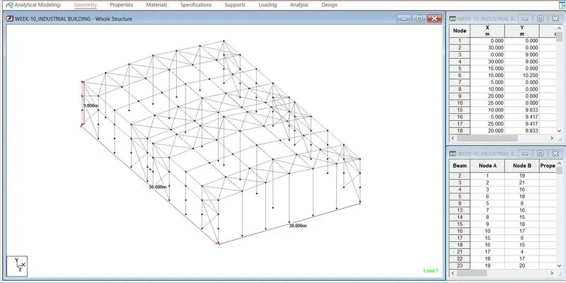
PROPERTIES:
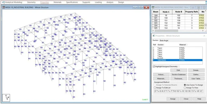
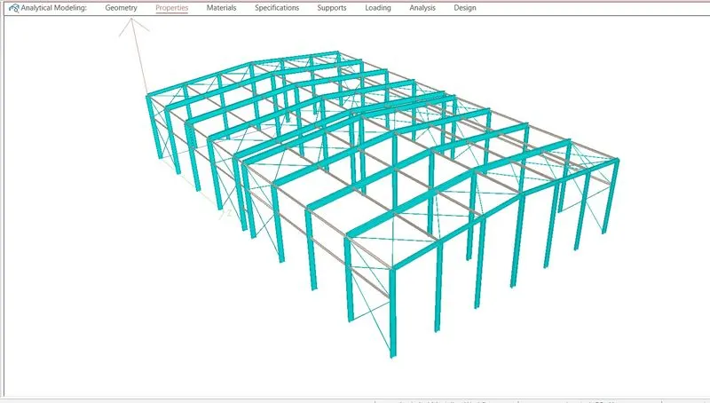
3D VEIW OBJECT:
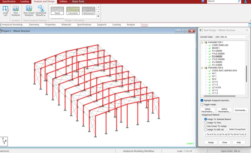
Material: STEEL
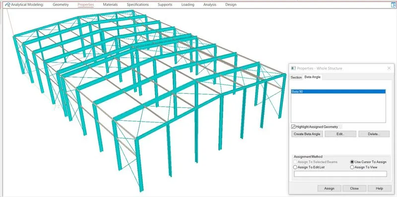
BETA Angle 90 degree for wind / gable columns
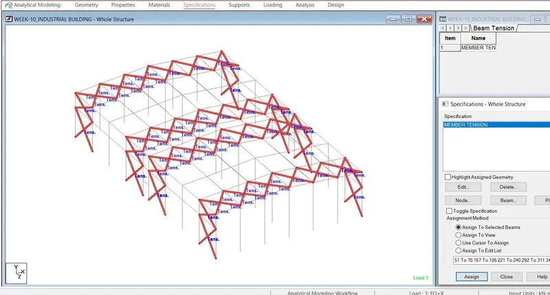
SPECIFICATION:
- Member Tension
- End MY MZ
- Start MY MZ
| LOAD CALCULATION IN STRUCTURE BUILDING | ||||||||
| Width | 30 | m | ||||||
| Length | 50 | m | ||||||
| Eave Height | 9 | m | ||||||
| Bay Spacing | 6 | m | ||||||
| Soil Type | Medium | |||||||
| Roof Slope | 1 in 12 | |||||||
| Location | Chennai | |||||||
| STEP 1 | LIVE LOAD CALCULATION | |||||||
| Live Load | 0.75 | kN/m | ||||||
| Rafter adding on UDL | 4.5 | kN/m | ||||||
| Main Frame Rafter | 3.375 | kN/m | ||||||
| Gaple Frame Rafter | 1.6875 | kN/m | ||||||
| EAVE GUTTER SIZE | 250X250X1mm | (Water Outlet Pipe) | ||||||
| 3.75 | kN | |||||||
| 1.875 | ||||||||
| STEP 2 | DEAD LOAD CALCULATION | |||||||
| F.O.S | 1.15 | (self weight) | ||||||
| Weight of roof Sheeting | 5 | kg | ||||||
| Weight of sag rods & braces | 5 | kg | ||||||
| Collatral load | 10 | kg/m^2 | ||||||
| Total Load | 20 | kg/m^2 | ||||||
| 0.2 | kN/m^2 | |||||||
| UDL on rafter | (main frame) | |||||||
| SPACING | 6 | |||||||
| 1.2 | kN/m | (UDL on Rafter) | ||||||
| UDL on rafter from purlin | IS811 | Taple 10 | ||||||
| Z=270X75X20X2.55 | 8.77 | kg/m | ||||||
| 30.06857143 | kg/m | |||||||
| 0.300685714 | kN/m | |||||||
| UDL on main frame | ||||||||
| 1.500685714 | ||||||||
| UDL on gaple frame | 0.750342857 | kN/m | ||||||
| DEAD LOAD ON COLOUMN | ||||||||
| Load on cloumn (main frame) | ||||||||
| Weight of side wall sheeting | 5 | kg/m^2 | ||||||
| Weight of sag rods & braces | 5 | kg/m^2 | ||||||
| Load from sag rods & brace | 10 | kg/m^2 | 0.1 | kN/m^2 | ||||
| 0.6 | kN/m | |||||||
| Weight of grid | 270*75*20*2.55 | 8.77 | kg/m | |||||
| 52.62 | kg/m | |||||||
| 0.5262 | kN/m | |||||||
| Total Load | 1.1262 | kN/m | (main frame) | |||||
| 0.5631 | (gaple frame) | |||||||
| DEAD LOAD EAVE STRUCT & CUTTER | ||||||||
| Point load | 270*75*20*3.15 | 10.7 | kg/m | |||||
| Weight of eave cutter | 5.8875 | kg/m | ||||||
| Load due to eave struct and cutter | ||||||||
| 16.5875 | kg/m | |||||||
| 145.140625 | kg/m | |||||||
| 1.45140625 | kN/m | (main frame) | ||||||
| 0.725703125 | (gaple frame) | |||||||
| WIND LOAD CALCULATION | ||||||||
| Wind preasure | Pz | 0.6*V^2 | ||||||
| Vz | Vb*k1*k2*k3*k4 | |||||||
| Vb | 50 | |||||||
| k1 | 1 | |||||||
| k2 | 1 | |||||||
| k3 | 1 | |||||||
| k4 | 1.15 | |||||||
| Vz | 57.5 | m/s | ||||||
| Wind preasure Pz | 1983.75 | 1.98375 | kN/m | |||||
| Design wind preasure | Pd | kd*ka*kc*Pz | ||||||
| kd | 1 | |||||||
| ka | 0.8 | |||||||
| kc | 0.9 | |||||||
| Pd | 1.4283 | kN/m^2 | ||||||
| Preasure co-efficient | ||||||||
| F | (Cpe-Cpi) A*Pd | |||||||
| Internal preasure co-efficient | Cpi | 0.5 | ||||||
| external | 0.5 | |||||||
| L/W | 1.666666667 | |||||||
| H/W | 0.3 | |||||||
| Roof angle | 1 in 12 | 4.76 | 5 | |||||
| Pd | 1.48 | kN/m^2 | ||||||
| governing spacing for rafter | 8.1 | |||||||
| gaple column | 6 | |||||||
| internal coloumn rafter length | 6.5 | |||||||
| Cpe value roof taple | (taple 6) | |||||||
| 0 | 90 | |||||||
| EF | GH | EG | FH | |||||
| -0.9 | -0.4 | -0.8 | -0.4 | |||||
| Cpe value on walls | ||||||||
| Degree | A | B | C | D | ||||
| 0 | 0.7 | -0.25 | -0.6 | -0.6 | ||||
| 90 | -0.5 | -0.5 | 0.7 | -0.1 | ||||
| WIND LOAD RAFTER | ||||||||
| Internal preasure co-efficient | 0.5 | |||||||
| External | -0.5 | |||||||
| ANGLE | FACE | Cpe | Cpe (+) | Cpi (-) | Cpe-CPI (+) | Cpe-CPI (-) | Pd (+) | Pd (-) |
| 0 | EF | -0.9 | 0.5 | -0.5 | -1.4 | -0.4 | -13.468 | -3.848 |
| GH | -0.4 | 0.5 | -0.5 | -0.9 | 0.1 | -8.658 | 0.962 | |
| 90 | EG | -0.8 | 0.5 | -0.5 | -1.3 | -0.3 | -12.506 | -2.886 |
| FH | -0.4 | 0.5 | -0.5 | -0.9 | -0.5 | -8.658 | -4.81 | |
| WIND LOAD COLOUMN | ||||||||
| Internal preasure co-efficient | 0.5 | |||||||
| External | -0.5 | |||||||
| ANGLE | FACE | Cpe | Cpe (+) | Cpi (-) | Cpe-CPI (+) | Cpe-CPI (-) | Pd (+) | Pd (-) |
| 0 | A | 0.7 | 0.5 | -0.5 | 0.2 | 1.2 | 1.924 | 11.544 |
| B | -0.25 | 0.5 | -0.5 | -0.75 | 0.25 | -7.215 | 2.405 | |
| C | -0.6 | 0.5 | -0.5 | -1.1 | -0.1 | -10.582 | -0.962 | |
| D | -0.6 | 0.5 | -0.5 | -1.1 | -0.1 | -10.582 | -0.962 | |
| 90 | A | -0.5 | 0.5 | -0.5 | -1 | 0 | -9.62 | 0 |
| B | -0.5 | 0.5 | -0.5 | -1 | 0 | -9.62 | 0 | |
| C | 0.7 | 0.5 | -0.5 | 0.2 | 1.2 | 1.924 | 11.544 | |
| D | -0.1 | 0.5 | -0.5 | -0.6 | 0.4 | -5.772 |
3.848 |
|
RAFTER DESIGN
| Design Of Rafter | |||||||
| Span of Rafter | 6 | ||||||
| Dead Load | 2.784 | kN/m | |||||
| Impossed Load | 7.875 | kN/m | |||||
| Length of Bearing | 100 | mm | |||||
| Yield Strength | 250 | N/mm^2 | |||||
| STEP 1 | DESIGN LOAD CALCULATION | ||||||
| Factored Load | 15.9885 | kN/m | |||||
| Factored Bending Moment | wl^2/8 | 71.94825 | kN/m | ||||
| STEP 2 | SECTION MODULUS REQUIRED | ||||||
| Z reqd | 316572.3 | mm^3 | |||||
| 316.57 | cm^2 | ||||||
| STEP 3 | SECTION CLASSIFICATION | ||||||
| PROPERTIES OF SELECTION SECTION | |||||||
| ISMB | 250 | ||||||
| A | 475.5 | mm^2 | |||||
| D | 250 | mm | |||||
| B | 125 | mm | |||||
| t | 6.9 | mm | |||||
| T | 12.5 | mm | |||||
| Izz | 5131.6 | cm^4 | |||||
| Iyy | 344.5 | cm^4 | |||||
| Zp | 459.76 | cm^3 | |||||
| Flange Crietersion | B/2T | 5 | |||||
| Wep Crietersion | (D-2T)/t | 32.60869565 | |||||
| e | 1 | ||||||
| B/2T | < | 9.4 | |||||
| (D-2T)/t | < | 83.9 | |||||
| The section classified as PLASTIC | |||||||
| STEP 3 | MOMENT OF RESISTANCE OF THE CROSS SECTION | ||||||
| MOMENT | Md | (zpxfy)/rm | |||||
| Md | 104.4909091 | kNm | |||||
| > | 71.95 | ||||||
| Hence section adequte for flexural | |||||||
| STEP 4 | SHEAR RESISTANCE OF THE CROSS SECTION | ||||||
| Shear Capacity | vc | 0.6fyAv/rm | |||||
| Av | 1725 | mm^2 | |||||
| Vc | 235.2272727 | kN | |||||
| V/Vc | 47.9655 | kN | |||||
| < | 0.6 | ||||||
| STEP 5 | CHECK FOR WEP BUCKLING | ||||||
| Slenderness of wep | 2.5d/t | ||||||
| d | 225 | ||||||
| 81.52173913 | |||||||
| Design Compressive stresses | Fc | 203 | N/mm^2 | ||||
| Pw | 31558 | N | |||||
| 315.58 | kN | ||||||
| > | 126 | ||||||
| Hence wep is safe against shear buckling | |||||||
| STEP 6 | CHECK WEP CRIPPING @ SUPPORT | ||||||
| Root Radius of ISMP 250 | R | 13 | mm | ||||
| tf+ R | 25.5 | mm | |||||
| n2 | 63.75 | ||||||
| Pcrip | 245625 | N | |||||
| 245.63 | kN | ||||||
| > | 126 | ||||||
| Hence section adequte for wep cripling | |||||||
| STEP 7 | CHECK FOR SERVICEABLITY- DEFLECTION | ||||||
| Design Load | 10.659 | kN/m | |||||
| Deflection | 17.52578387 | mm | |||||
| Allowaple Deflection | 30 | mm | |||||
| Hence serviceability is satisfied | |||||||
BASE PLATE DESIGN
| DESIGN OF BASE PLATE | ||||||||
| STEP 1 | Strength of Concrete | Fcu | 40 | N/mm^2 | ||||
| Yield strengrh of Steel | fy | 250 | N/mm^2 | |||||
| Material Factor | ym | 1.1 | kN | |||||
| Factored Load | 600 | kN | ||||||
| STEP 2 | STEEL COLOUMN SECTION | |||||||
| Thickness of flange | 12.7 | mm | ||||||
| STEP 3 | AREA REQUIRED | |||||||
| Bearing Strength of concrete | 0.4 Fcu | |||||||
| 16 | N/mm^2 | |||||||
| Area Required | 37500 | mm^2 | ||||||
| Let size of plate | Bplate | 450 | mm | |||||
| Dplate | 300 | mm | ||||||
| Area of palte | 135000 | mm^2 | ||||||
| Let projection on each side | a = b | 25 | mm | |||||
| w | 4.444444444 | N/mm^2 | ||||||
| CI 7.4.3.1 | Thickness of slap base | ts | 4.204374826 | mm | ||||
| < | 12.7 | mm | ||||||
| So use plate of 450x350x16mm | ||||||||
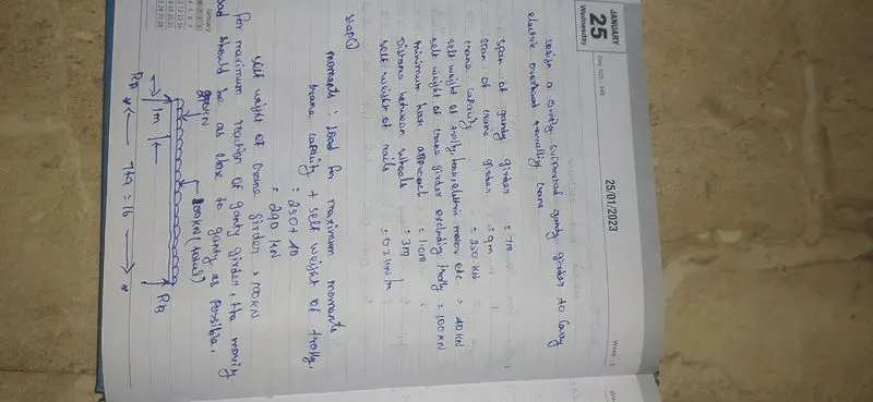
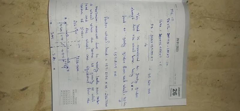
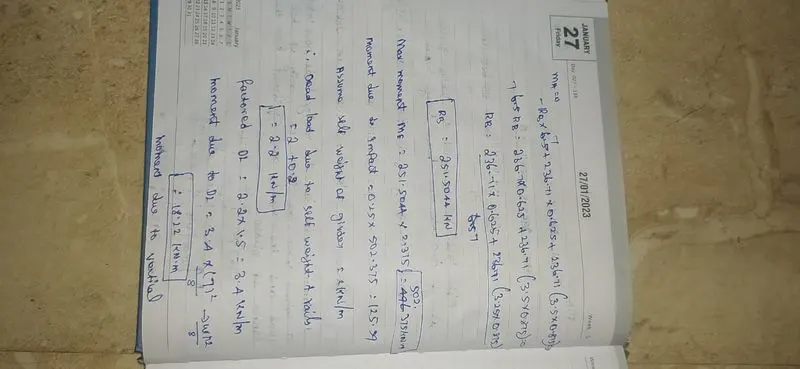
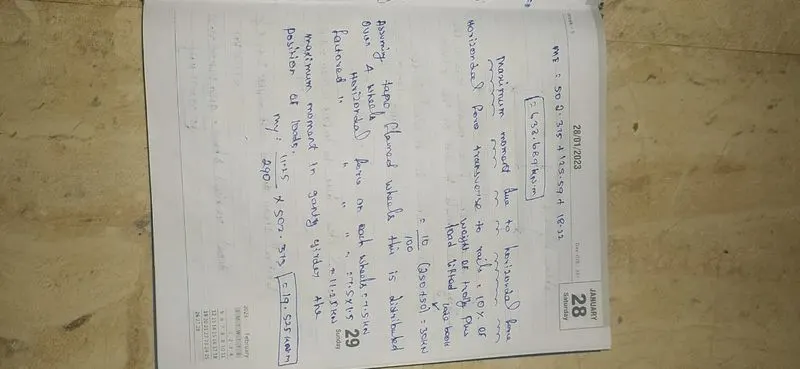
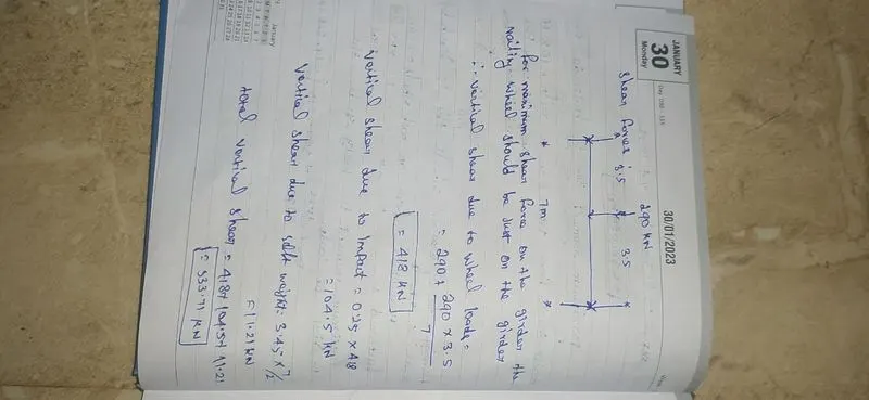
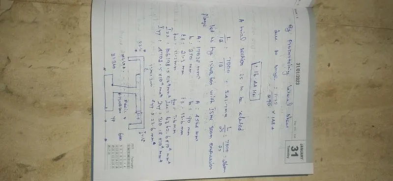
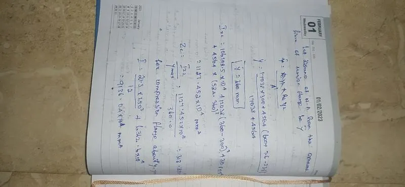
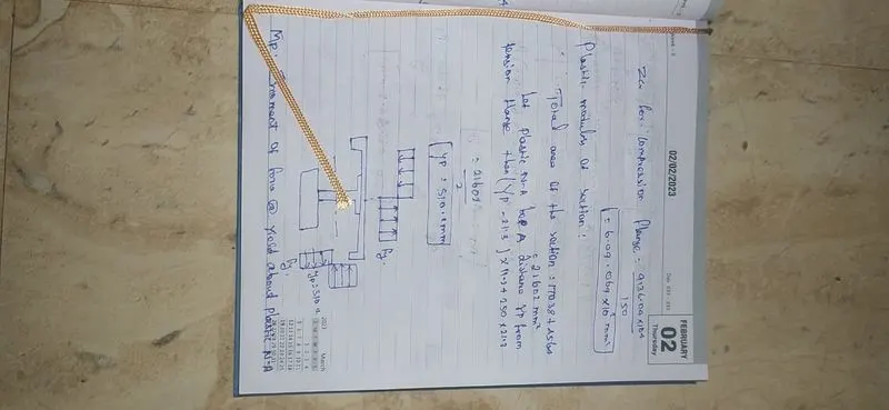
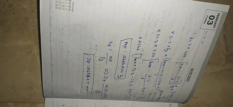
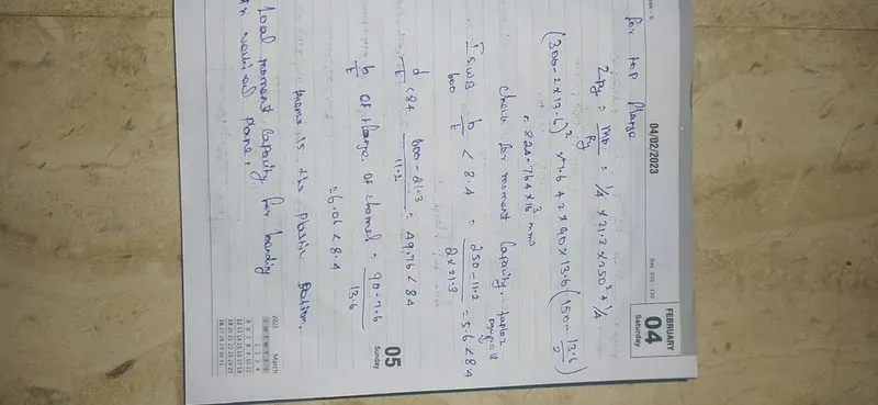
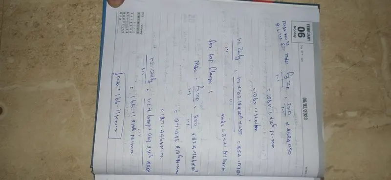
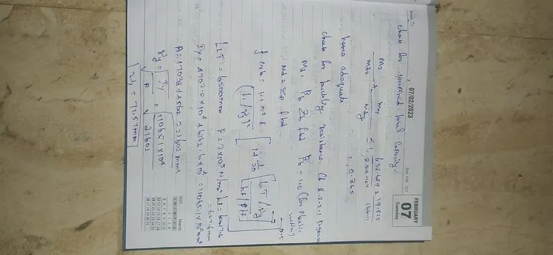
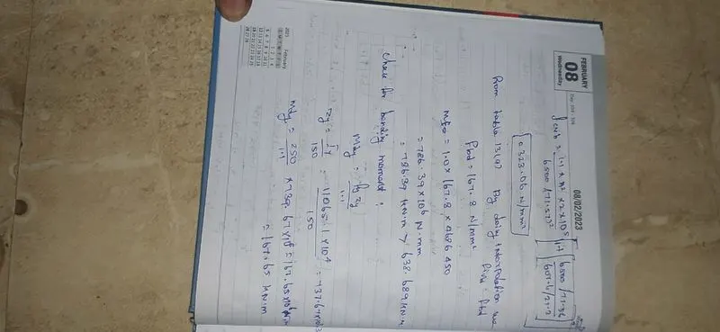
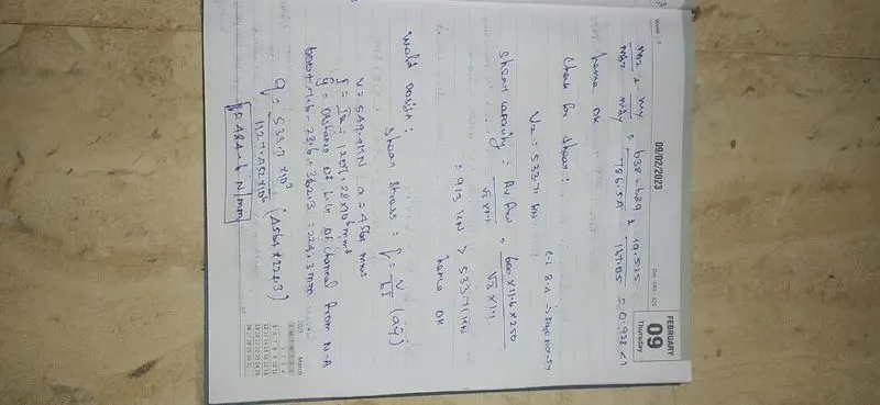
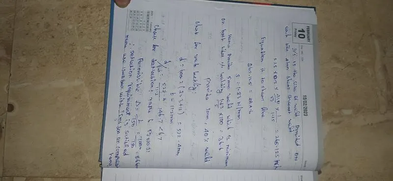
2. Design a simply supported gantry girder to carry electric overhead travelling crane
Given:
Span of gantry girder = 7 m
Span of crane girder = 9 m
Crane capacity = 250 kN
Self-weight of trolley, hook, electric motor etc. = 40 kN
Self-weight of crane girder excluding trolley = 100 kN
Minimum hook approach = 1.0 m
Distance between wheels = 3 m
Self-weight of rails = 0.2 kN/m