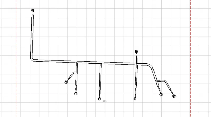
Project 2
AUTOMOTIVE WIRING HARNESS BACKDOOR:
PROCESS
- CREATING ASSEMBLY CONTEXT:
Download the backdoor cad data from given our website.
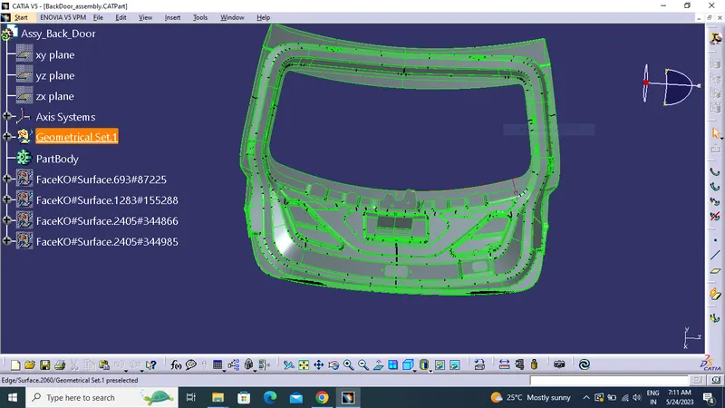
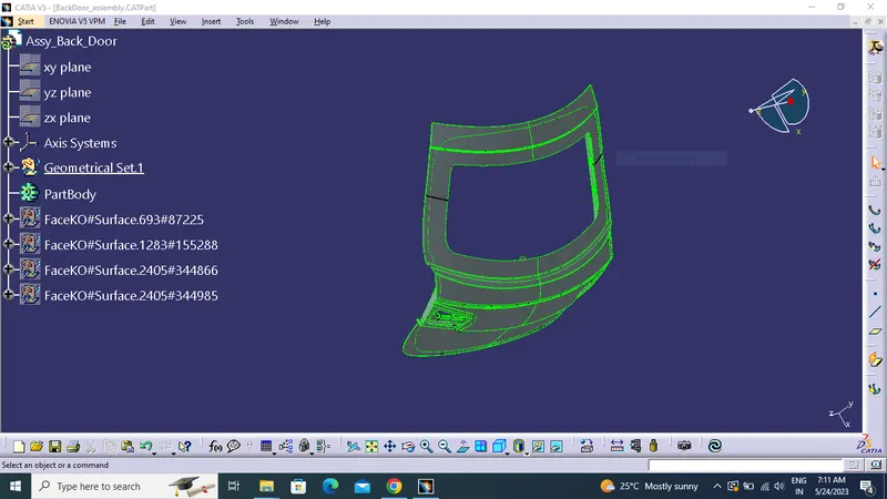
- DEFINING CONNECTOR ELECTRICALLY
- Choosing right components for the wire harness routing.
- Using the components for backdoor upper and lower lights, wiper motor, sensors, and defogging equipment.
- Define all component electrically.
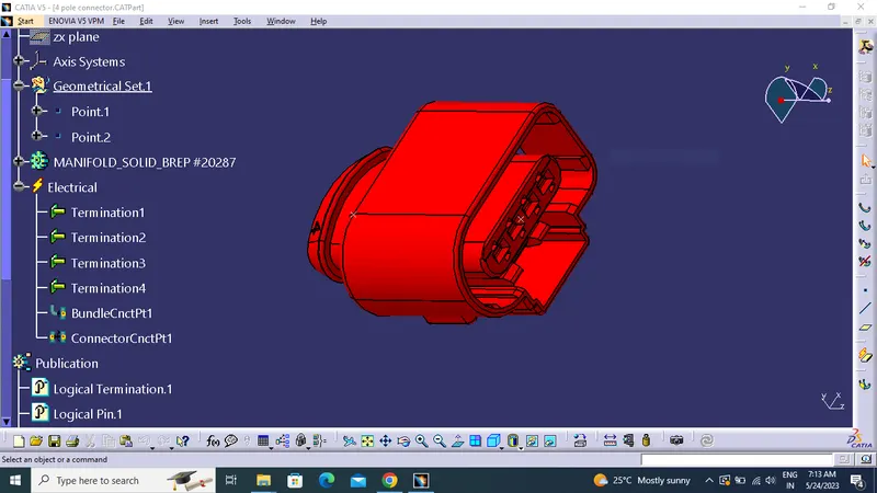
Interconnection Connector
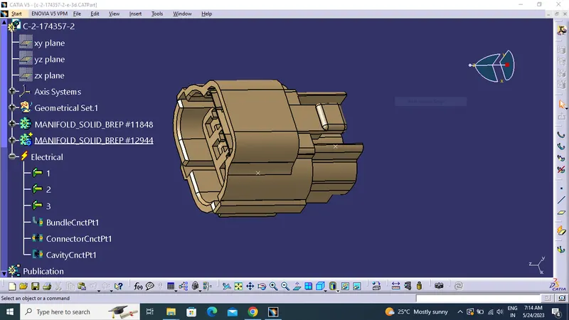
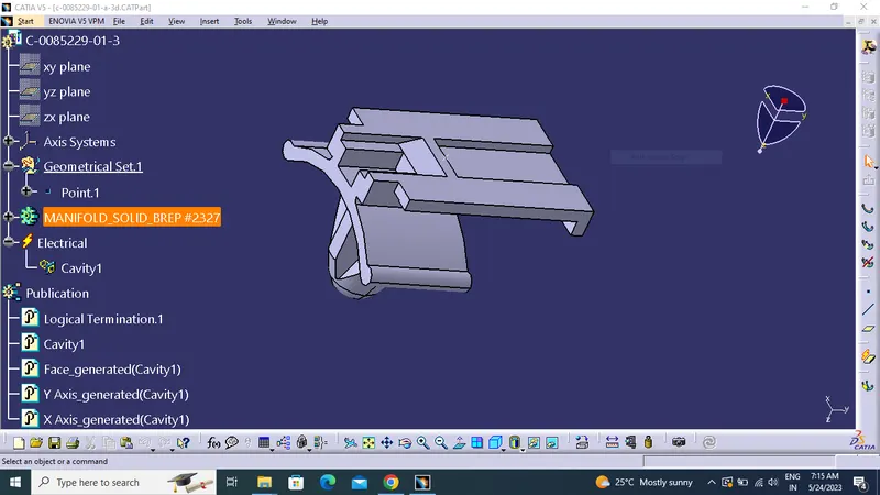
4 Pole Connector
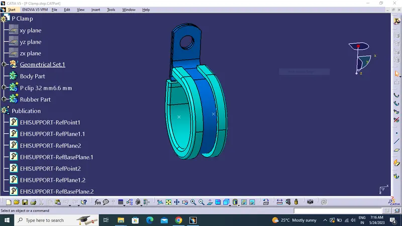
P clamp
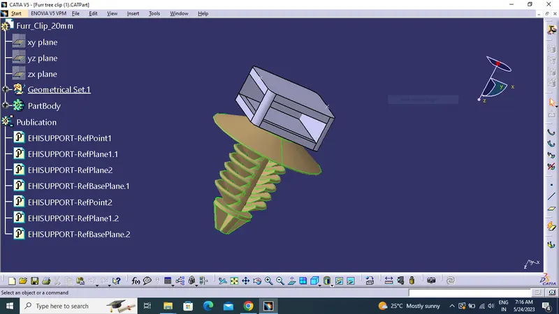
Furr Tree Clip
L clamp
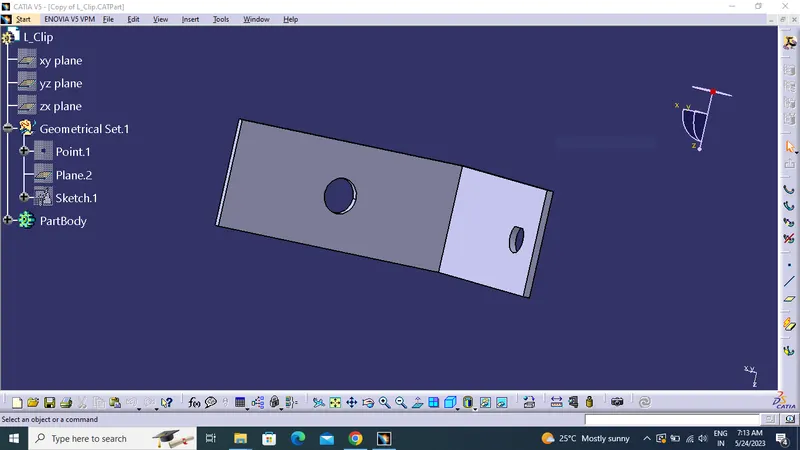
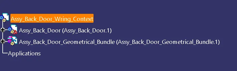
CREATING ASSEMBLY
- First create assembly context product file and add all component .
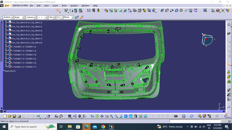
ADDING COMPONENTS
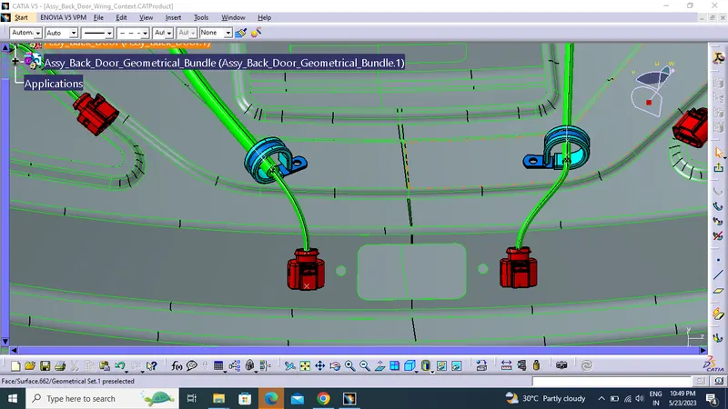
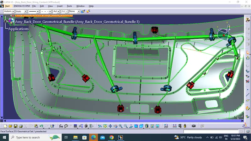
- Adding all the connector clips, clamps in required position.
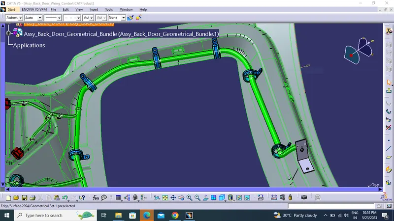
- we place the p clamps for the support in the needed positions.
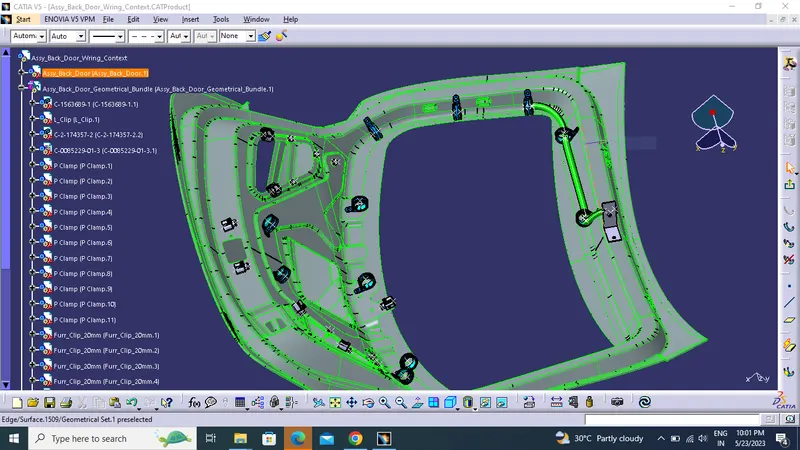
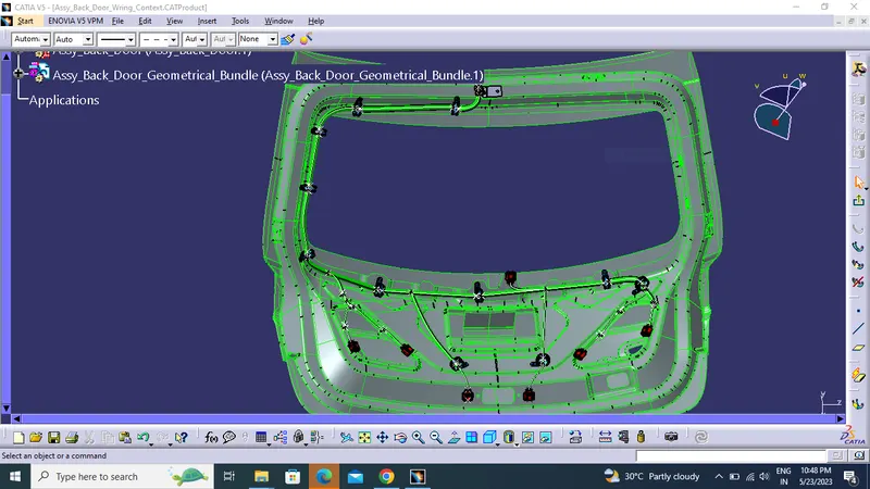
BUNDLE ROUTING
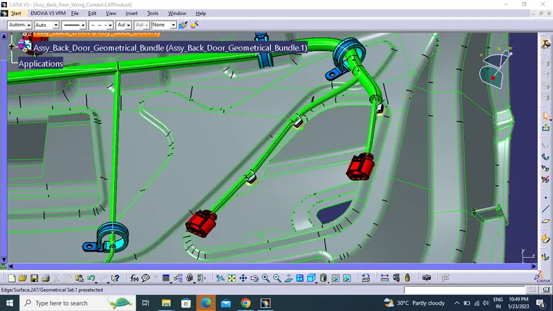
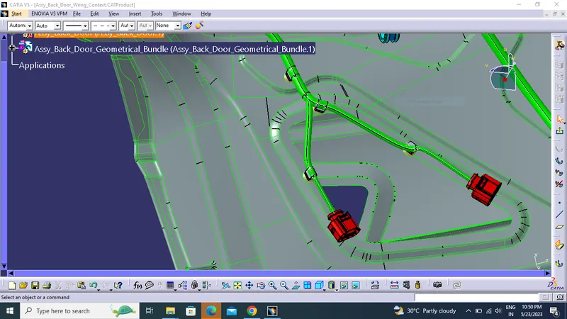
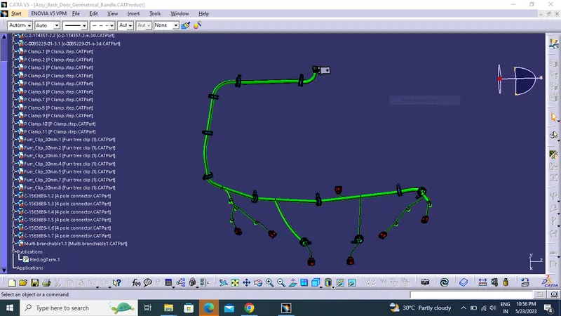
- Adding all the connector, clips and clamps as required position with the help of manipulation tool, and using of compass.
- All the clamps and fir tree clips are positioned.
- Then define the geometrical bundle and next step to routing.
HARNESS CONTINUITY
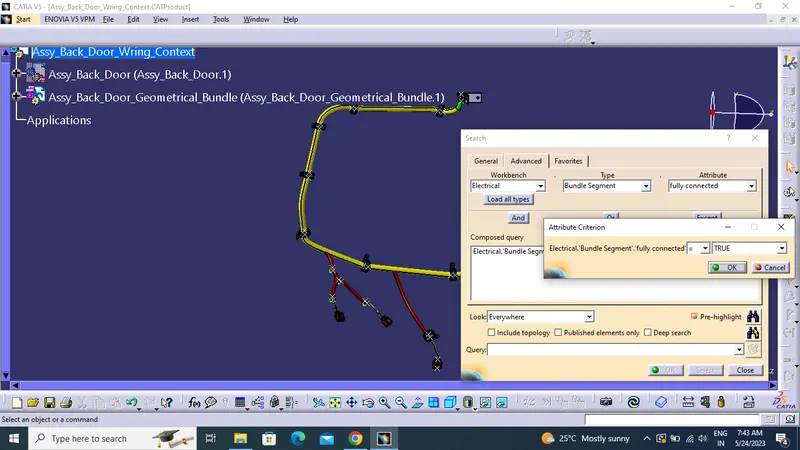
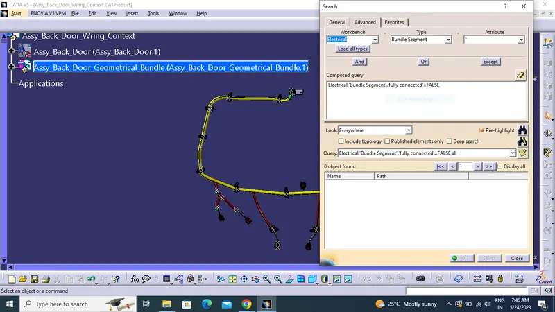
- Select the multibranch before we check bundle continuity
- By selecting flase option showing theresult of discontinuity of harness bundle.
PROTECTION COVERING
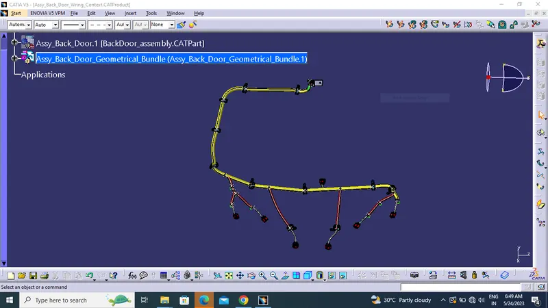
- Using protection covering tool we protect all the bundle.
- We have created a catlouge for cot tube.
CREATING FLATTENING VIEW
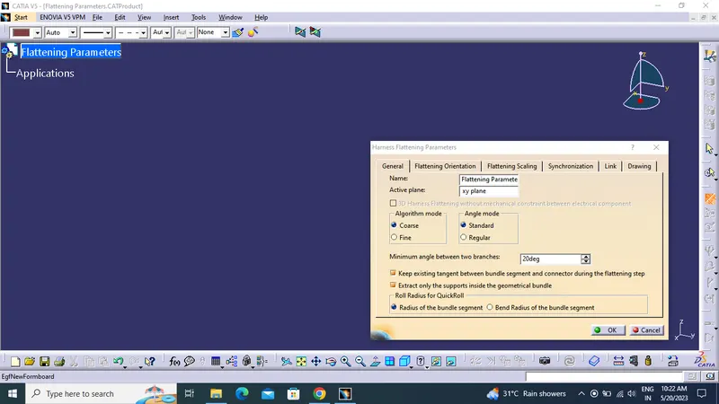
- First we create the new product file and add flatening parameter setting as required.
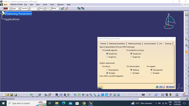
- Drawing setting for drafting.
- Rename the product file as the Flattening Product.

- Bring the harness assembly into the newly created Flattening Product by using the "Extract" feature.
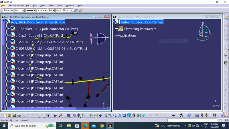
CREATING DRAFTING
- Creating new drawing file and rename the sheet.
- Click front view icon and select the any face that taken as front view.
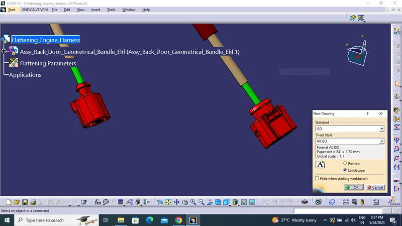
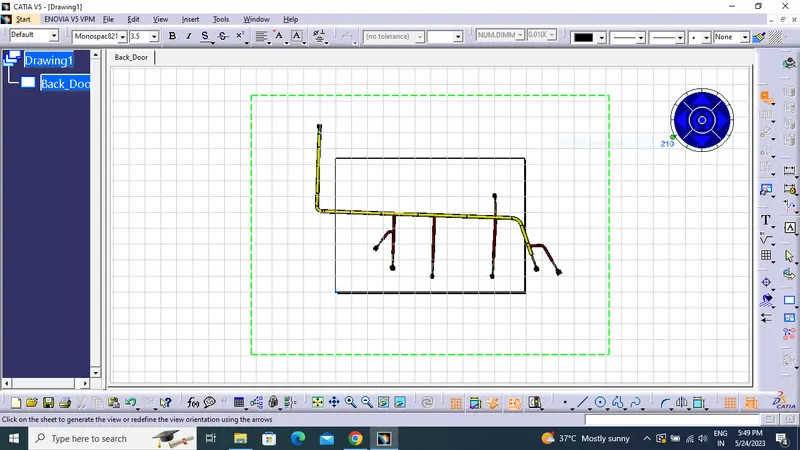
- Click "dress-up" settings 3D wireframe in always "ON". If this setting is not selected the bundle segments will not be visible on the drawing view.
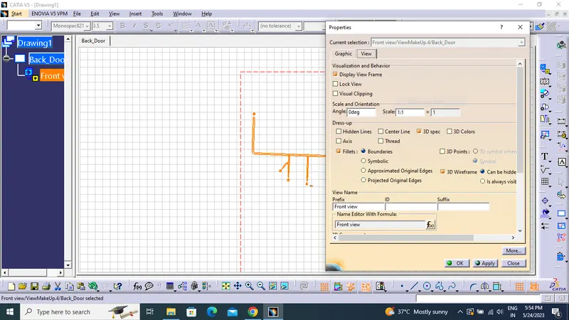
- Final flattened drawing was produced for the wiring harness.