Project 2
Using MATLAB/simulink and the drive cycle from the attached excel sheet, find-
The max heat generation of the battery
The SOC of the battery at 2 *104second of the battery operation
|
Time |
Time Step |
Battery Current |
|
00:00.4 |
0.1 |
-0.9632 |
|
00:00.5 |
0.2 |
-0.952 |
|
00:00.6 |
0.3 |
-0.9072 |
|
00:00.7 |
0.4 |
-0.9632 |
|
00:00.8 |
0.5 |
-1.0304 |
|
00:00.9 |
0.6 |
-0.9632 |
|
00:01.0 |
0.7 |
-1.0304 |
|
00:01.1 |
0.8 |
-1.008 |
|
00:01.2 |
0.9 |
-0.9856 |
|
00:01.3 |
1 |
-0.9632 |
|
00:01.4 |
1.1 |
-0.9184 |
|
00:01.5 |
1.2 |
-0.9296 |
|
00:01.6 |
1.3 |
-0.9296 |
|
00:01.7 |
1.4 |
-0.9296 |
|
00:01.8 |
1.5 |
-0.9184 |
|
00:01.9 |
1.6 |
-0.9408 |
|
00:02.0 |
1.7 |
-0.896 |
|
00:02.1 |
1.8 |
-0.9072 |
|
00:02.2 |
1.9 |
-0.9072 |
|
00:02.3 |
2 |
-0.9408 |
|
00:02.4 |
2.1 |
-0.9296 |
|
00:02.5 |
2.2 |
-0.9296 |
|
00:02.6 |
2.3 |
-0.9968 |
|
00:02.7 |
2.4 |
-0.9968 |
|
00:02.8 |
2.5 |
-0.9408 |
|
00:02.9 |
2.6 |
-0.9408 |
|
Battery resistance |
2 milli ohm |
Consider the battery resistance is 0.5 mOhm, delta time is 0.1 and entropic factor is 2.
1.The max heat generation of the battery
Heat Generation:
Batteries generate heat during charge and discharge due to enthalpy changes, electrochemical polarization, and resistive heating inside the cell. Temperature variation inside the batteries can lead to the uneven temperature distribution which creates uneven charge/discharge behaviour within the battery pack. So, thermal runaway may occur in a cell when heat is not properly controlled and possibly cause fire and explosion.
For this the maximum current taken from given drive cycle
The maximum current in the drive cycle is -0.896 at the time 2 minutes (120 seconds)
Therefore
Resistance = 0.5 milli ohm
Maximum joule heat generated=I^2*R*t
= (-0.896) ^2*0.5 *120
Maximum joule heat generated = 48.16 milli Joule
Entropic factor=2
Maximum heat generated= max joule heat + entropic heat
= 48.16+2
Maximum heat generated =50.16 milli joule
Maximum of heat generation of battery is 50.16 milli joule
2.The SOC of the battery at 2 *104second of the battery operation
What is SoC?
In simple words (The State of Charge) is your fuel gauge for battery-operated vehicles or E-vehicle. It is the real-time or actual capacity of the battery compared to its full capacity. Just like your cellphone battery, it is measured in terms of percentage (%). E.g., 100% SoC means the battery is fully charged to its capacity, and 0% SoC means it’s fully discharged.
The importance of calculating SoC
I will admit that the estimation of the SOC of a battery is not an easy task depending. It definitely varied based on the battery type and the type of application that is using the battery. However, there has been good research work and development in past years to improve the estimation of SOC accuracy. Accuracy in SOC estimation is one of the important tasks for battery management systems, which will help improve system reliability and performance and improve the battery life cycle.
In general SoC of the battery is calculated by the simple formula given below, i.e.ratio of real-time charges present in a battery(Qt) to full battery capacity charges (Qn).
SoCt=Qt/Qn

Though, if you can actually estimate precise SOC calculation, then you will save yourself from unpredictable system blockage. It will prevent you from overcharging your batteries, which, in reality, damages your battery’s internal structure.
However, you cannot estimate the accurate SOC under every condition because it involves complicated chemical and physical processes.
Voltage Method
Under a controlled environment, you can determine the real-time pending capacity of a battery, SOC, by using a discharge test method. In the voltage method, battery voltage is converted to equivalent SOC value using the battery’s predefined discharge curve (voltage vs. SOC). Anyhow, the battery’s electrochemical kinetics and temperature affect the battery’s voltage.
You can rely on the voltage method by using a lookup table of the battery’s open-circuit voltage (OCV) vs. temperature. As well as, by a correction term proportional to the battery current and by compensating the voltage reading.
The voltage method is however difficult to implement because it needs a stable voltage range for the batteries. In addition, this discharge test is very time-consuming because it includes a consecutive recharge when there are many applications.
Errors in this method are shown below
Voltage fluctuation
Noise in the system
Cell chemistry.
SoC Estimation by Coulomb Counting is based on the measurement of the current and integration of that current over time.
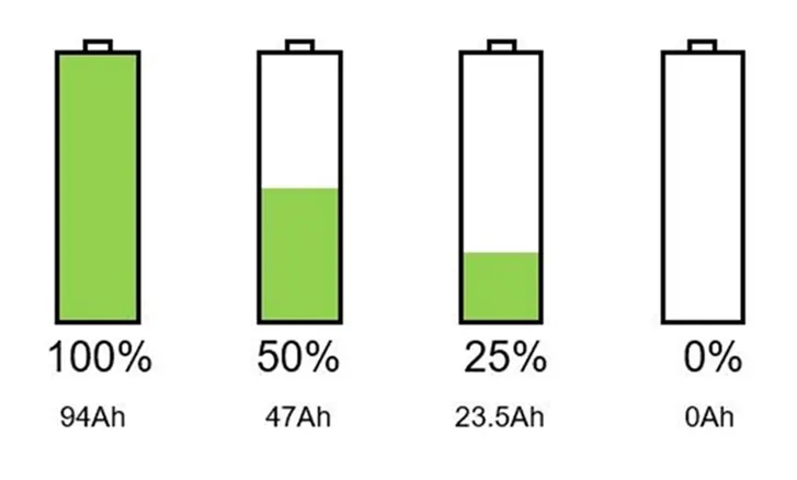
The State of charge (SoC) of a battery cell is required to maintain it’s safe operation and lifetime during charge, discharge and storage. However, SoC cannot be measured directly and is estimated from other measurements and known parameters. This leads to errors in the estimated SoC and that means it is not possible to fully exploit the full capability of the cell.
Coulomb counting gives a relative change in SoC and not an absolute SoC. If you measure the current over a given time step you have a measure of the number of Ah that have left or been received by the battery.
The Coulomb counting method measures the discharging current of a battery and integrates the discharging current over time in order to estimate SOC. The coulomb counting method is done to estimate the SOC with respect to time. Which is estimated from the discharging current I(t), and previously estimated SOC values, SOC(t-1). SOC is calculated by the following equation.

where:
SoC(t)= estimated State of Charge at time, t
SoC(t-1)= previous State of Charge at time t-1
I(t)= charging or discharging current at time, t
Qn= battery cell capacity
Δt= time step between t-1 and t
But there are several factors that affect the accuracy of the Coulomb counting method including temperature, battery history, discharge current, and life cycle. The coulomb counting method depends on the recording of the current noise only. The signal is filtered with a high pass filter with a cut-off frequency of 0.01Hz.
If you want to know the absolute SoC you need to know the starting SoC of the cell, SoC(t-1) as given in the equation. One option is to fully charge the cell to a known voltage. Charging to maximum cell voltage and SoC can be used as a reset and known point.
Modified Coulomb Counting method:
To improve the Coulomb counting method, a new technique called modified Coulomb counting method is proposed. The modified Coulomb counting method uses the corrected current to improve the accuracy of estimation.
The corrected current is the function of discharging current. There is a quadratic relationship between the corrected current and discharging current of battery. By practice of experimental data, corrected current is calculated by the following form:
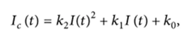
where , k2, k1 and k0 are constant values obtained from the practice experimental data.
In modified Coulomb counting method, SOC is calculated by the following equation:
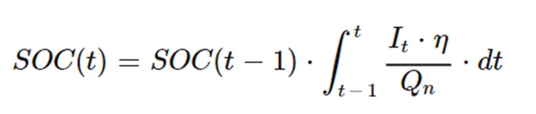
The experimental results show that the accuracy of the modified Coulomb counting method is superior to the conventional Coulomb counting method. The Coulomb counting method then calculates the remaining capacity simply by accumulating the charge transferred in or out of the battery.
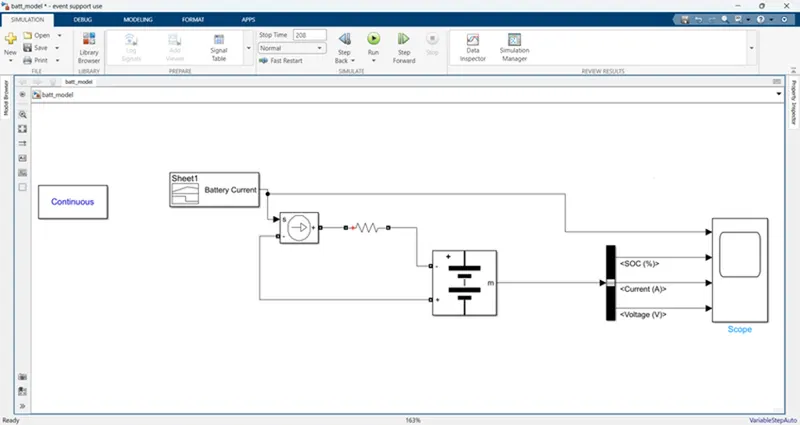
For The SOC of the battery at 2 *104second of the battery operation is checked by creating a model in simulink by using battrey,controlled current source,signal builder,bus selector & scope
The model is shown below
In the signal builder i am taking the given drive cycle as shown below
First click on the file and select the import file
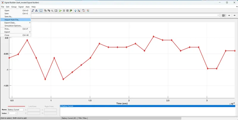
and then browse the file and select the excel file(drive cycle is copied to excel and save a excel file)
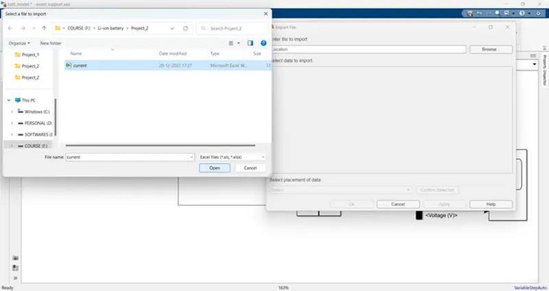
and then click on confirm selection and apply to the signal builder

And then the signal builder as shown below
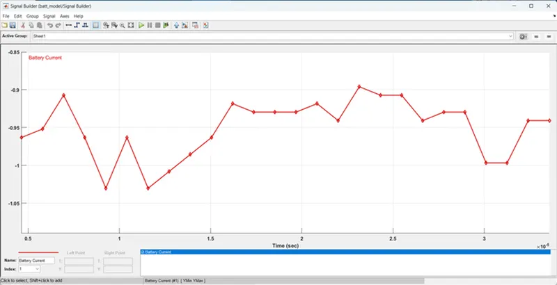
Model explanation:
After importing the file it is connected to controlled current source and the current sourse is +ve terminal is connected to battery -ve terminal through a resistor (becuase of the battery have some resistance) and the current source of -ve terminal is connected to battery +ve terminal and the battery out put is connected to bus selector in that i am selecting the SOC, current & voltage and is connected to scope.
All block parameters are shown below
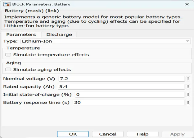
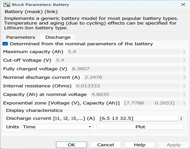
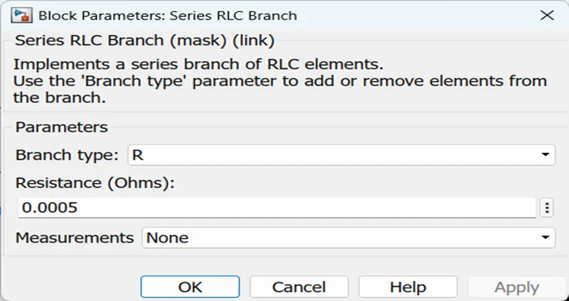
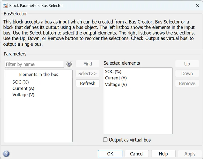
After that i am running the simulation for 208 sec the results are shown below
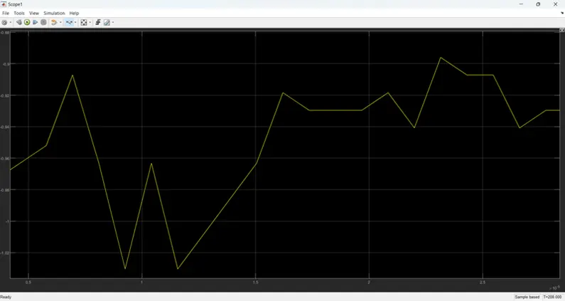
The current is negative becuase of the battery is charging condition
The soc,current & voltage of cell is shown below
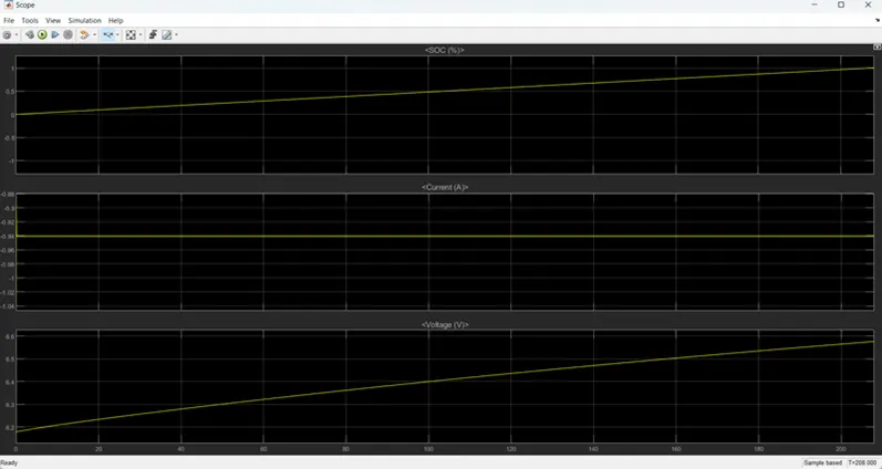
The first one is Soc of the cell it is from raised from 0 to 1 beacuse of battery is in charging mode
The second plot is current of the battery
The third plot is voltage of the battery it raised from 6.2v to 6.6v
After zomming the plot like shown below
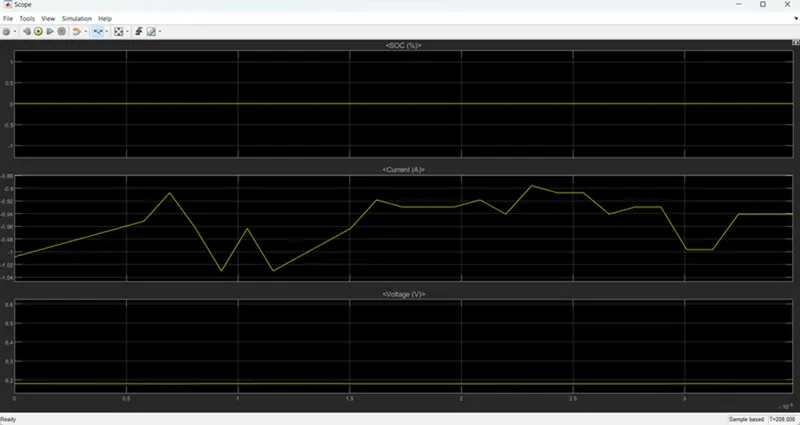
The current is same as input.