Project 2
Designing interleaved isolated DC-DC converter
- Input voltage: 45 – 60 v
- Output voltage: 3 V
- Output current: 100A
Rout= Vo/Iout= 0.03Ohms
for higher efficiency, I've implemented interleaved flyback converter with the feedback
Circuit diagram
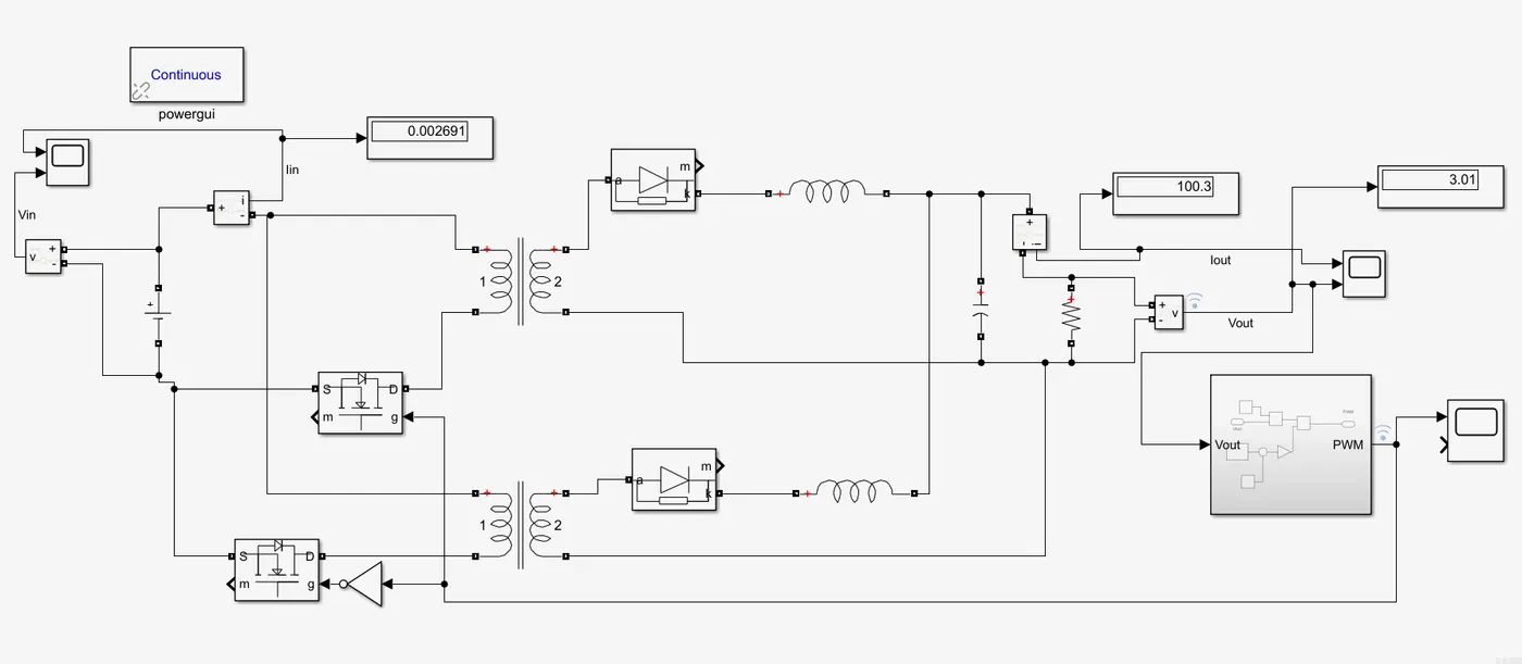
The reason for implementing this design, in the first charging cycle the upper primary side will store energy and it will be transferred to the secondary side when the switch is turned off. Similarly, when we turn on the switch in the lower loop the bottom primary side gets charged and the energy is transferred to the secondary side. This way at any moment we see the energy flow in the secondary side or output side of the converter. This results in higher in keeping the output current tied to the required value.
Feedback loop
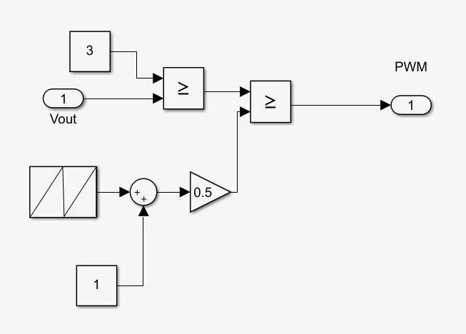
This is a very classical feedback loop that never fails to tie the desired output. The output voltage is compared with the 3V constant block, then the resulting error is compared with a sawtooth signal of 20kHz pulsating between 0 and 1. Thus resulting in the absolute PWM signal for the MOSFET switch to drive.
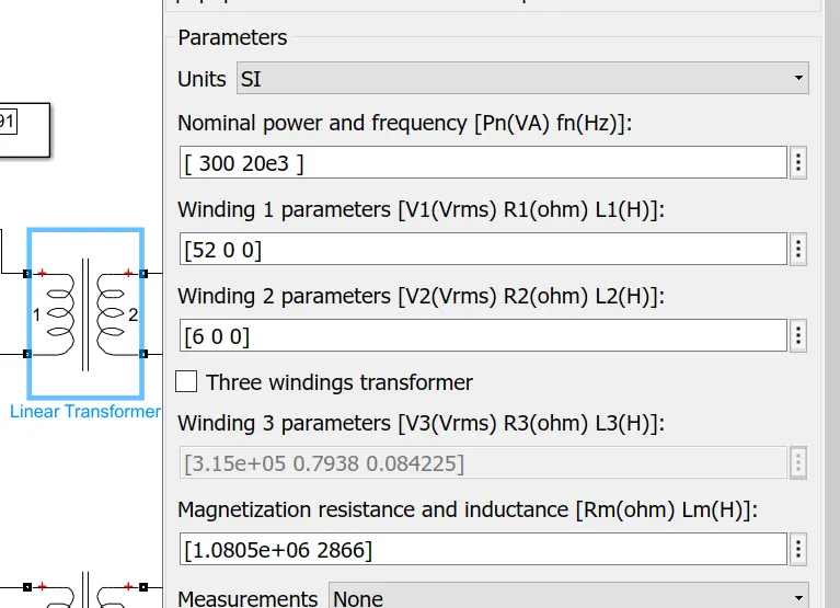
Linear Transformer
The linear transformer used in the circuit has the following configuration
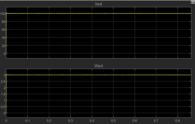
Output current and voltage
Input current and voltage
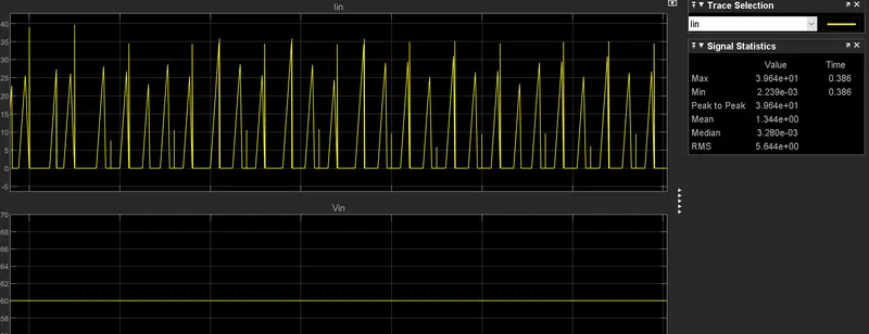
Calculating Efficiency
Vin=60V
Iin (RMS)- 5.5Amps
VOut- 3V
Iout- 100Amps
Efficiency - Pout/Pin
Pout-300W
Pin-324W
Efficiency- 90%