Project 2
All required files of connector, fir tree clip are downloaded from TE Connectivity.
- Connector Defination
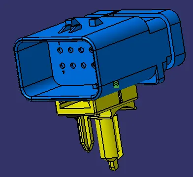
Downloaded 4p and 12p connectors for assembly and interconnection. Created geometry for electrical parameters like points, axis system at bundle connection, connector connection and cavity connection area.
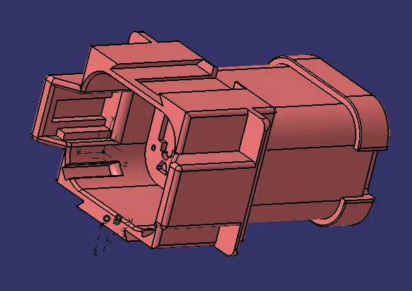
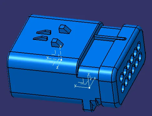
Entered in elctrical part design workbench and defined all required parameters for connectors.
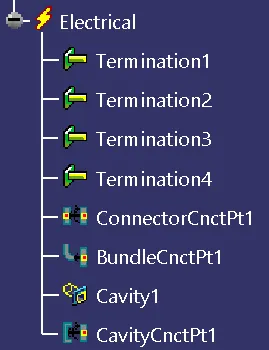
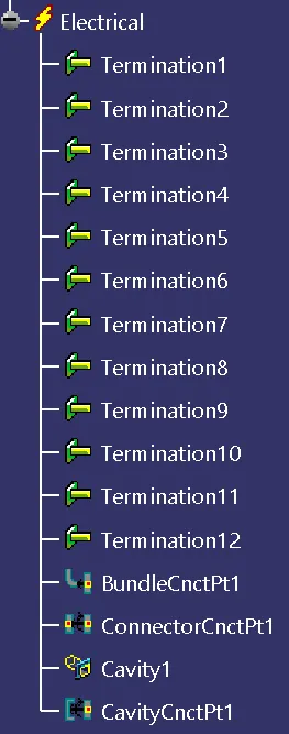
- Mounting Equipments
Furr tree clips are used for connector and harness mounting. Created axis system for clips and clamps and defined support part in electrical part design workbench as shown in images.
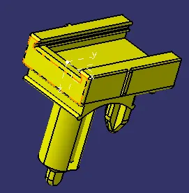
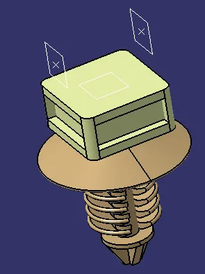
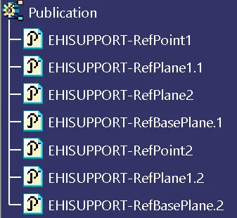
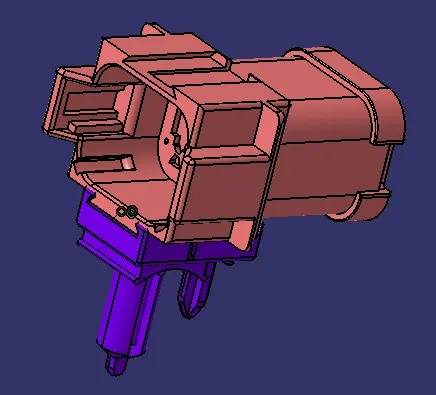
Created assemblies for connector and mounting clips. Imported and connected connector and cavity using command Connect Electrical Devices.
- Protection Covering
Created COT Tubes catalogue for storing protection covering appliences. Created protection covering for harness with diameter 12MM, 35MM, 20MM, 10MM, 5MM.
- Context Assembly Creation
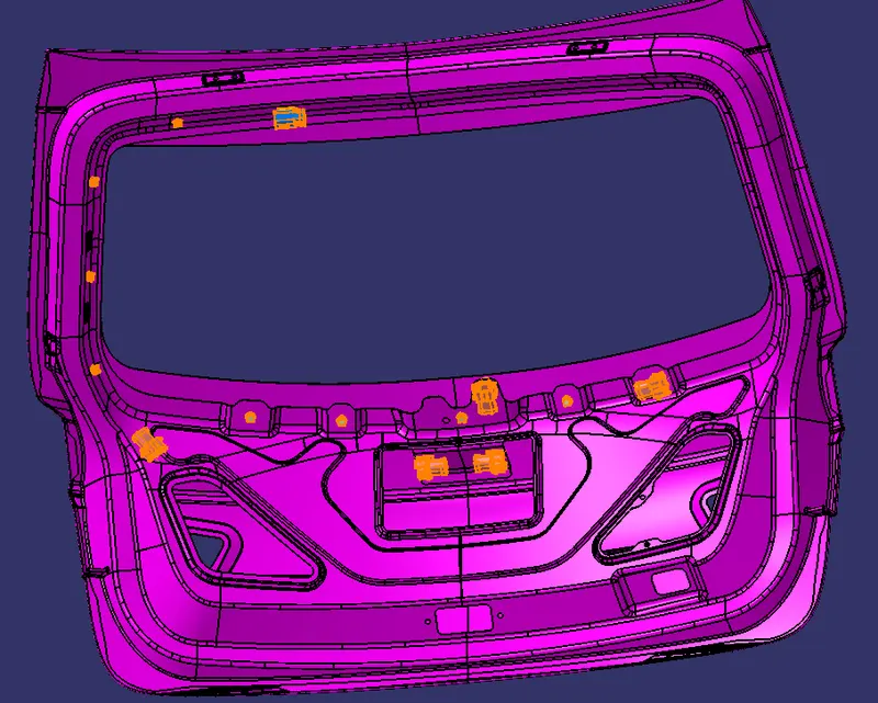
New assembly file created for context assembly and imported Backdoor model. Created one component and imported 12P Connector assembly(1 nos), 4P Connector assembly(5 nos), Furr clips(8 nos).
12P Connector is used for backdoor interconnection.
2)4P Connector is used for tail lamps, number plate light, reverse camera and rear wiper.
Finally positioned all equipments as per their position using Manupalation, compass, snap and smart move.
- Harness Routing
Created multibranchable document and started routing the bundle. From interconnection to tail lamp connector, the diameter for harness bundle is provided 10mm.
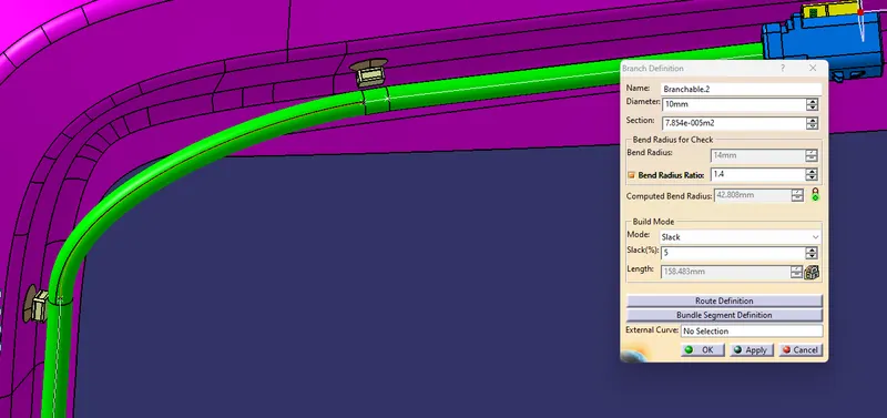
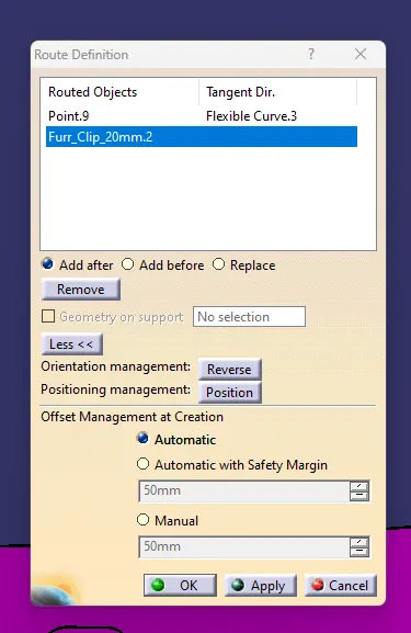
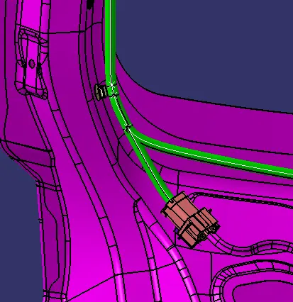
Added slack as per requirement and created branch points at 2 positions. Created bundle from branch points to tail lamp, reverse camera, number plate light and rear wiper with diameter 5mm.
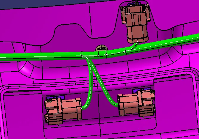
(Bending radius is 1.4mm provided for all bundles)
- Protection Covering Application
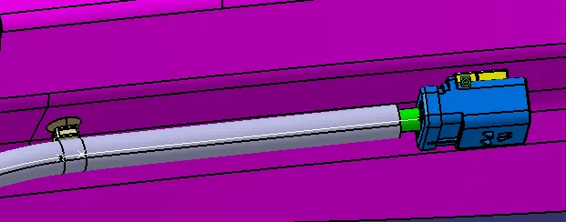
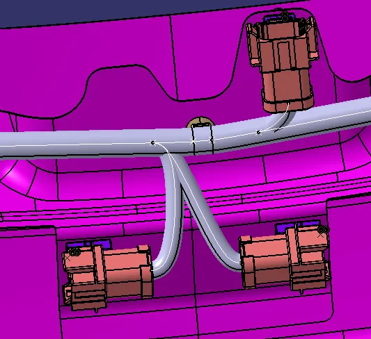
Added protection covering of 12mm at bundle of 10mm diameter and 10mm at bundle of 5mm diameter. Specified extrimity as per requirement at end and start points.
- Harness Flattening
Entered in harness flattening workbench, defined flattening parameters and extracted the context assembly with all attached equipments.
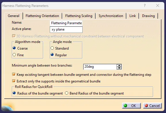
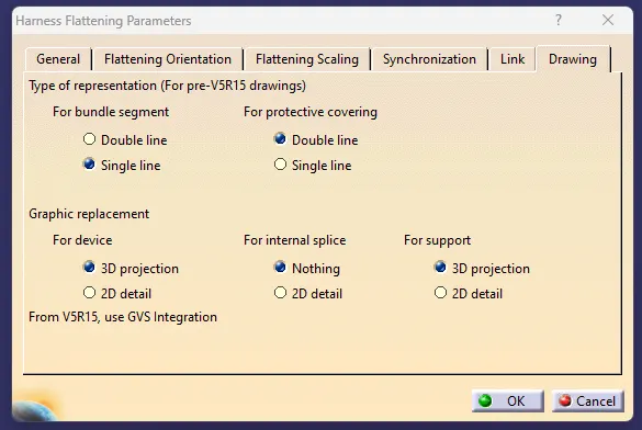
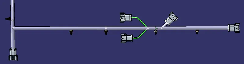
Using flatten, straighten, roll and rotate command, geometry gets simplified and positioned as per XY plane for drawing creation.
- Harness Drawing
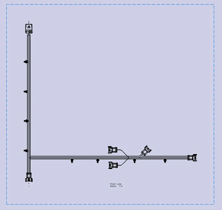
Created drawing document with sheet size A0 and imported the flattened view for harness drawing creation. Created sheet background and modified drawing properties as shown in image.
Saved all files and created .zip file for submission.
Thank you....