Project 2
CPU FAN BEZEL MOLD DESIGN USING SOLIDWORKS
OBJECTIVE:
Creation of Mold for a CPU Fan Bezel using SolidWorks.
INTRODUCTION:
The injection molding process involves heating & injecting plastic material under pressure into a closed metal mold tool. The molten plastic cools & hardens into the shape inside the mold tool, which then opens to allow the moldings to be ejected or removed for inspection, delivery, or secondary operations.
Injection molding is a manufacturing process that allows for parts to be produced in large volumes. It works by injecting molten materials into a mold. It is typically used as a mass production process to manufacture thousands of identical items. Injection molding materials include metals, glasses, elastomers, and confections, although it is most commonly used with thermoplastic and thermosetting polymers.
WORKING:
The first stage of injection molding is to create the mold itself. Most molds are made from metal, usually aluminum or steel, and precision machined to match the features of the product they are to produce.
Once the mold has been created by the mold-maker, the material for the part is fed into a heated barrel and mixed using a helical-shaped screw. Heating bands melt the material in the barrel and the molten metal or molten plastic material is then fed into the mold cavity where it cools and hardens, matching the shape of the mold. The cooling time can be reduced through the use of cooling lines that circulate water or oil from an external temperature controller. Mold tools are mounted on plate molds, which open once the material has solidified so that ejector pins can eject the part from the mold.
METHODOLOGY:
The injection molding process requires careful design, including the shape and features of the part, the materials for the part and the mold, and the properties of the molding machine. As a result, various considerations need to be taken into account when injection molding.
Step 1: Draft analysis
Draft analysis Examines the faces of the model for sufficient draft, to ensure that the part ejects properly from the tooling. By using draft analysis we check if there are any missing drafts in the model and do the necessary changes.
Draft analysis was set to 0.5 degrees and checked if any features require a draft.
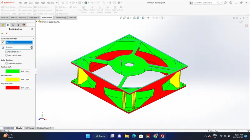
We can notice that no Draft is required for the model we can continuing the mold design process without making any changes to the model.
Step 2: Scaling
Depending on the material, the part will shrink when cooled after molding. Therefore our mold needs to be a little larger than we want our final part to be. So we will scale up our part.
Assuming the material for the model as ABS (shrinkage - 0.6%), the scale value is determined as (0.6/100)+1=1.006 for the model.
Since there will be shrinkage we scale the model to 1.006% to avoid shrinkage.
Step 3: Parting lines
Now we need to separate the model into core and cavity. for this, we use the parting line command. Parting lines are made to separate into core and cavity.
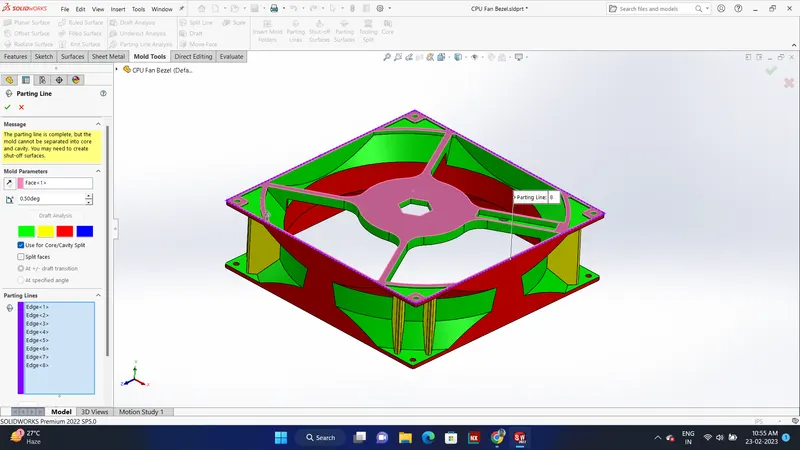
Step 4: Shut off surfaces
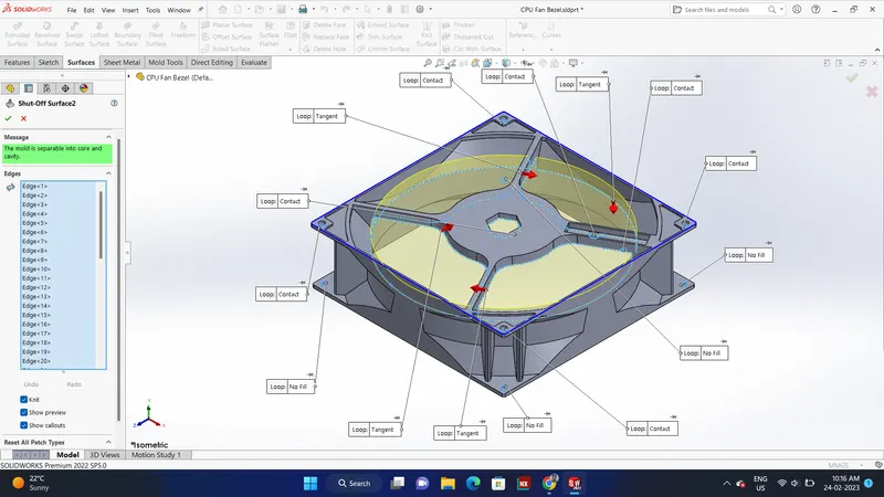
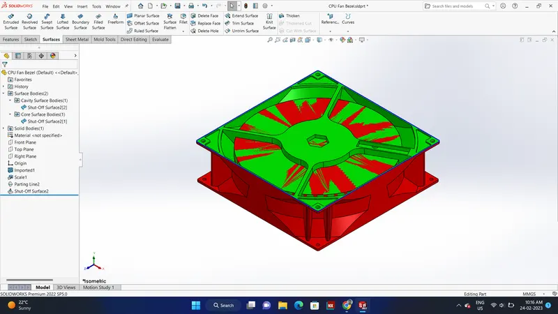
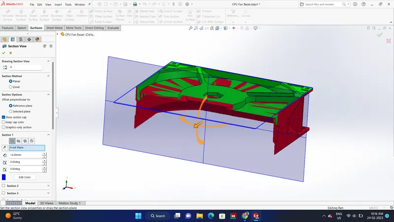
We can observe that there are few openings in the part. we have to cover these parts before creating the mold. For this, we use the shut-off surface command. All the opening holes are covered using a shut-off surface.
Shut-off surface Creates surface patches to close up through holes in the molded part.
Step 5: Parting surfaces
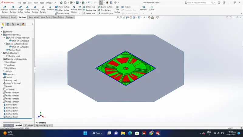
The parting surface is made along the parting line to separate the core from the cavity.
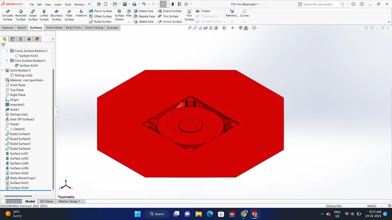
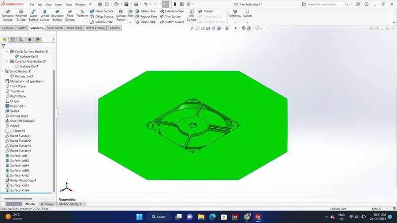
Step 6: Creating core & cavity surfaces
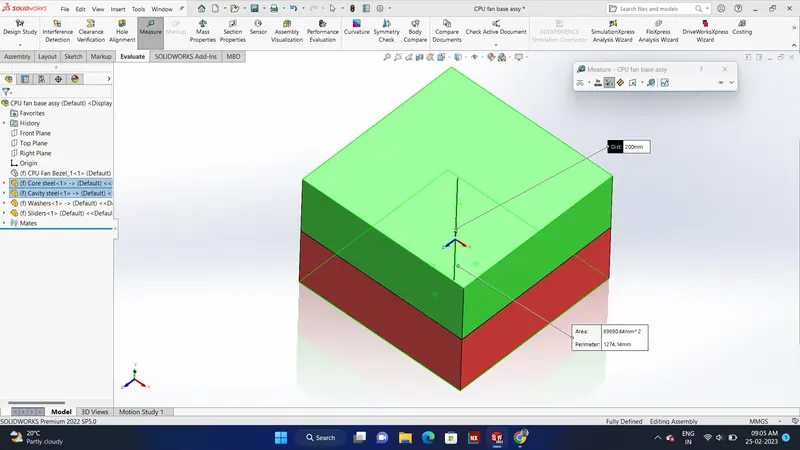
Step 7: Open core cavity in assembly
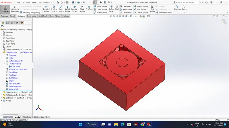
Step 8: core block was created
Stop 9: created a parting surface for the core block
Step 10: cut the core block with the surface to create a core block
Core Block
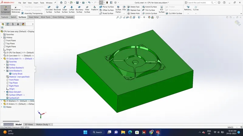
Cavity Block
Ejector pins
Ejector pins are created for the part to be pushed out from the core when the part has cooled down.
Created relief for Ejector pins
Sliders
Undercuts are those features in an injection-molded part that prevent its ejection from the mold
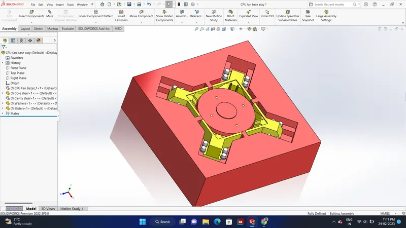
During mold design of the Plastic knob in the step of the draft analysis, we can clearly observe an undercut is present, to optimize the undercut sliders will be used. Slider direction will be perpendicular to the direction of the tooling direction which will be horizontal and these are separable from the core and cavity blocks as the sliders are movable, they should have a base for the movement from the model we can easily provide a base while creating the blocks itself.
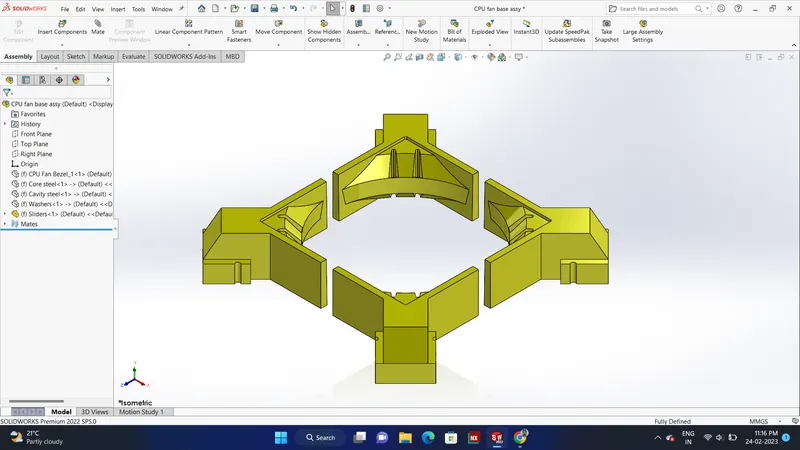
To prevent this we create Sliders. Sliders are separate blocks created which can be slid out of the mold before the part is removed thus preventing the obstruction by the undercuts.
Sliders are created using the split command by sketching the profile of the undercut and the plane up to where it has to split.
We first identify the part having an undercut and then create a movable slider to optimize the undercut.
Steps followed:
Step 1: Identify the undercut
Step 2: Make a sketch covering the undercut area and make a slider block
Step 3: Provide a vedge on the slider and do changes to the dimensions of the slider to accommodate finger cam
Step 4: add extra material to the slider to accommodate washers
Step 5: create a locking mechanism.
Inserts
Inserts are used in the mold when there are parts or places in the mold where the tooling will be difficult. we create a separate insert to make the tooling process easy.
We check for the model to see if there are any constraints in the tooling. If there are any constraints we create an insert to provide smooth and easy tooling
Steps followed:
Step 1: Select the face around the ribs and sketch an insert block
Step 2: separate the insert from the core by using split command and provide colors to differentiate
Step 3: create bolts to insert the inserts to the core.
Washers and locking mechanism
Washers are created on the core block between the slider and the core block.
Along with this, we provide a locking mechanism where the slider locks after traveling a certain distance.
Ejectors
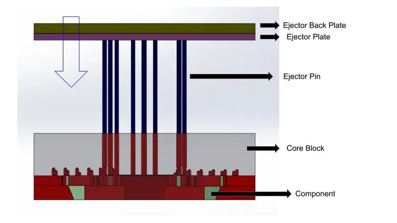
For ejection of the component, the entire ejection system will move In the direction of the core block and the mold will be completely ejected
Ejector pins:
Ejector pins are created for the part to be pushed out from the core when the part has cooled down.
Ejector pins connect the ejector plates and the part.
- 2D sketch and created circles and used split command to make ejector pins
- Created relief for ejector pins for free motion of the pins.
- Here for this model we create a D-shaped pin since the base of the part is inclined.
Ejector Plates:
Ejector plates are created by sketching a rectangle and by using extrude command.
Step 19:Runners and Gates:
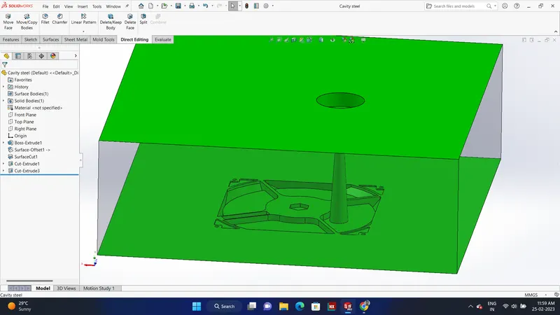
The sprue leads into the runner from the molding nozzle, which then directs the melt into the mold cavity through the gate. At the end of the runner is the gate leading into the mold cavity. The gate leaves a surface blemish on the part. It is small and designed to freeze before the part, runner, or sprue freeze.
Sprue pullers are provided so that sprue comes out along the core block in the downward direction.
Runner diameter calculation
D = (W^1/2 * L^1/4) / 3.7
Where D is runner diameter (in mm)
W is part weight (in g)
L is runner length (in mm)
In this model, we create a trapezoidal runner with a draft of 10 degrees on all sizes of the runner.
Air vents:
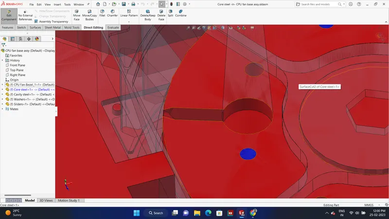
Air vents are a small channel provided in the mold block for the easy escape of air. When the mold block closes after one cycle of molding there will be some amount of air gap in the mold. If we do not provide an escape, air will be present in the mold block, leading to defects in molded components. Therefore we create air vents.
Air vents should be designed for the mold to remove trapped air in the blocks for this a gap of 0.02mm will be provided on the core block with a way for the air to escape out the block.
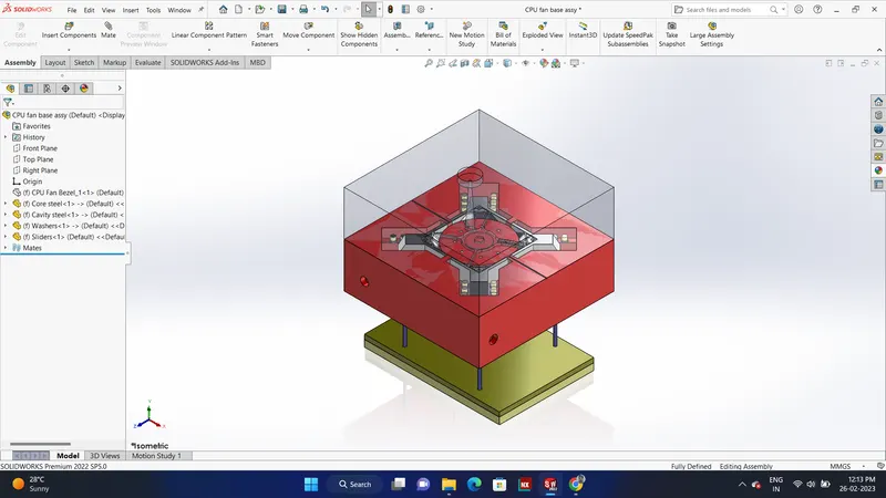
Cooling Channels:
We create cooling channels by keeping in mind that we should provide uniform cooling throughout the mold so that defects such as warpage do not occur.
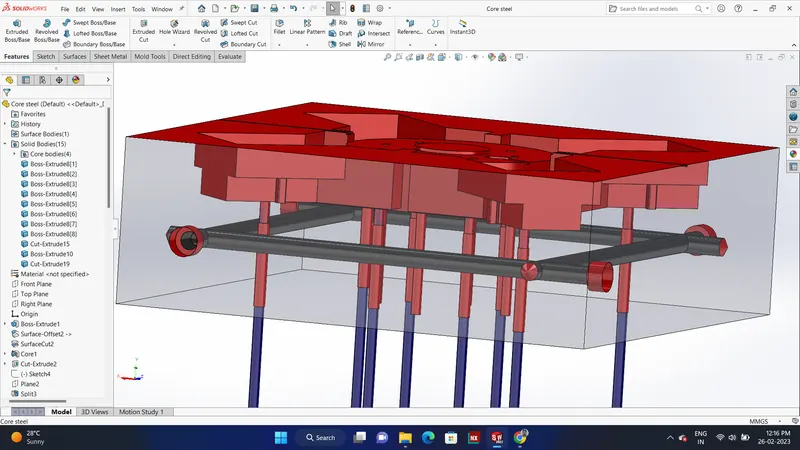
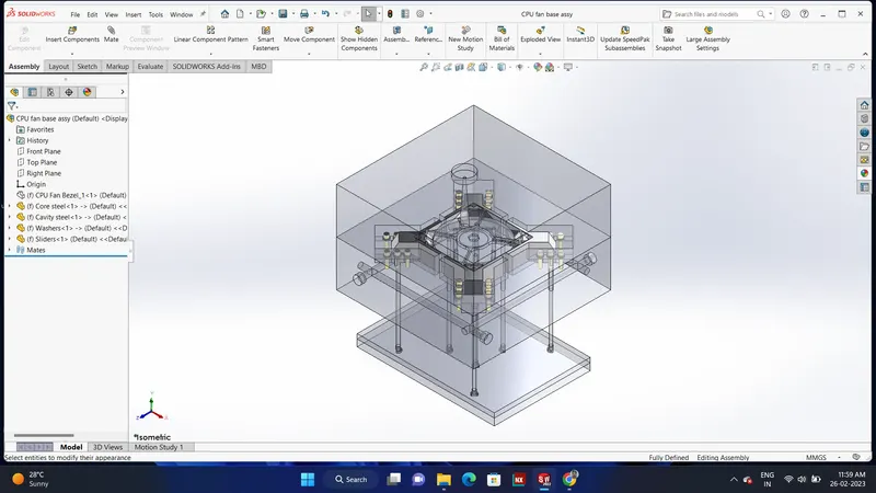
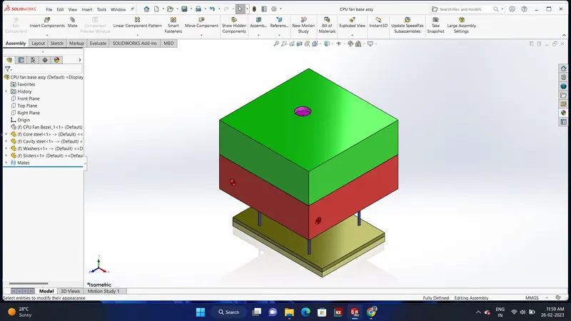
Final View of Mold design
The most important features and commands in SolidWorks used to design the mold
- Draft Analysis: Examines the faces of the model for sufficient draft, to ensure that the part ejects properly from the tooling.
- Undercut Analysis: Identifies trapped areas that prevent the part from ejecting.
- Parting Line Analysis Analyzes transitions between positive and negative drafts to visualize and optimize possible parting lines.
- Parting Lines This tool has two functions:
- Verifies that you have drafted your model, based on the angle you specify.
- Creates a parting line from which you create a parting surface. The Parting Lines tool includes the option to select an edge and have the system Propagate to all edges.
- Shut-off Surfaces Creates surface patches to close up through holes in the molded part.
- Parting Surfaces Extrude from the parting line to separate mold cavity from the core. You can also use a parting surface to create an interlock surface. See Interlock Surface.
- Ruled Surface Adds draft to surfaces on imported models. You can also use the Ruled Surface tool to create an interlock surface.
- Tooling Split Creates the core and cavity bodies, based on the steps followed earlier.
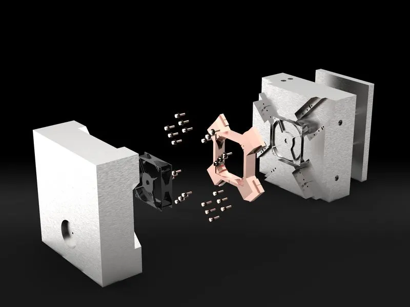
Result:
Hence, by adopting these methodologies steel molds with a proper ejection system with ejector pins and plates, runner and gate system, air vents, and cooling channels for the mold are successfully designed using SolidWorks.