Project 1- Traffic Jam Assistant Feature
Jam Assistant Feature
AIM :
- Model Development of a single feature of Traffic Jam Assist using MATLAB & Simulink as well as Code Generation using Embedded Coder .
Objectives :
- Model Development as per MBD guidelines . Creation of Simulink Data Dictionary .
- Code Generation using Embedded Coder Generating Model Advisor Report .
-
Data Dictionary creation :
(TrafficJamAssistant.sled )
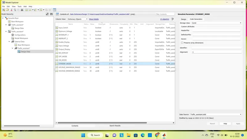
- A new Simulink data dictionary is created and updated signals & calibration Data List as per our requirements .
- The very first thing that we will do is create a Simulink Data Dictionary using the given Signal and Calibration Data List.
-
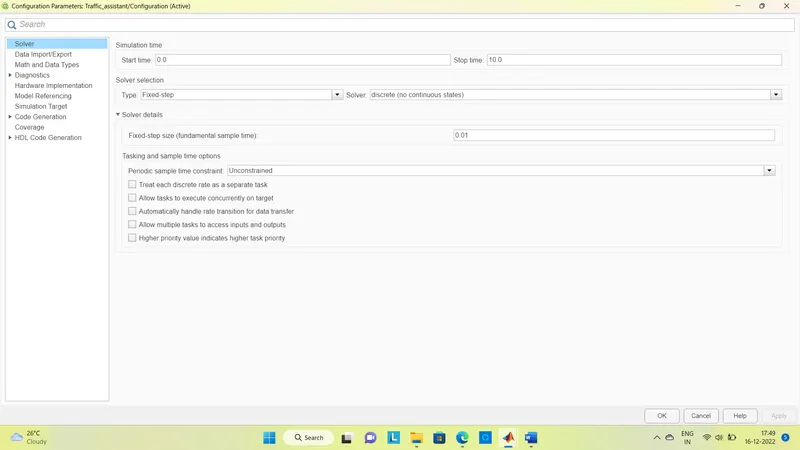
Solver configuration parameter :
- Solver type : Fixed
- Solver : discrete ( no continuous states ) Sample time : 0.01
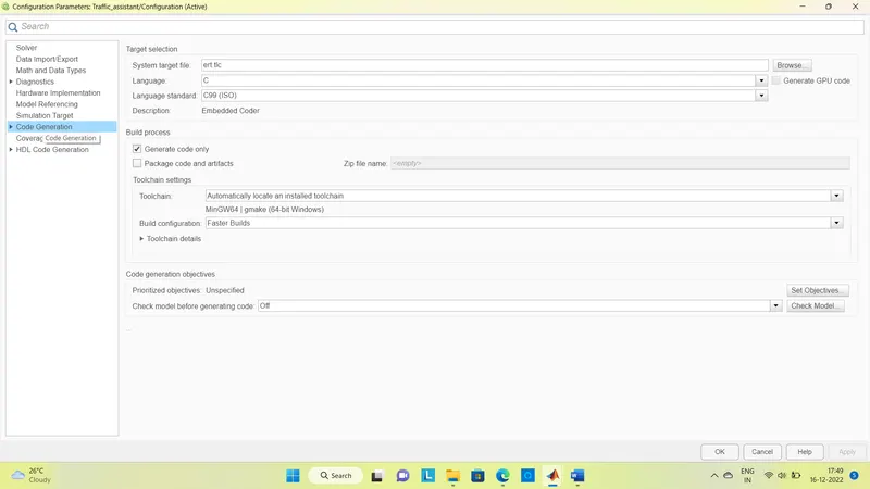
- Code generation Parameters : System target file : ert.tlc ( Embedded Coder ).
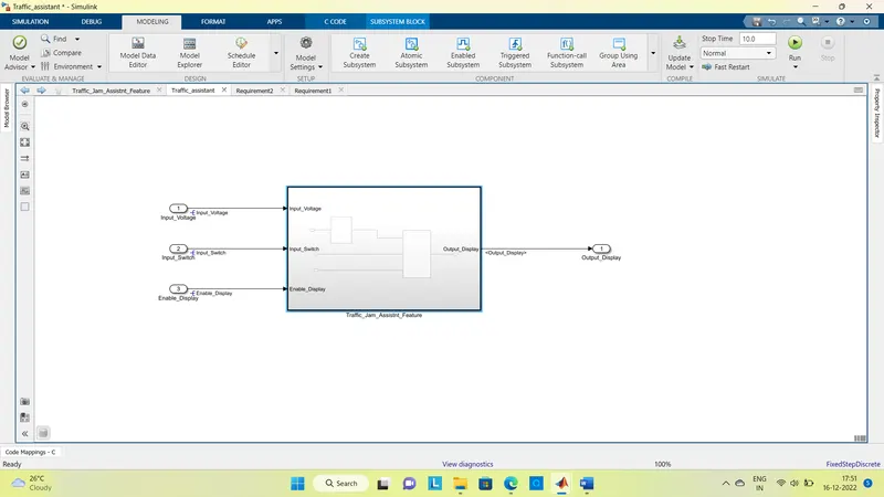
Designing MATLAB Simulink Model :
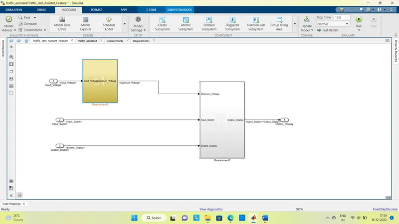
- The Input Voltage , input Switch , and the Enable switch are the inputs to the system , and the Output Display is the final Output from the system .
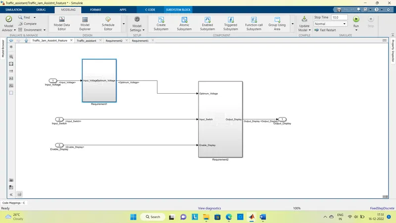
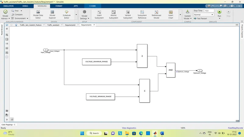
Requirement 1 :
- Input Signal " Input_Voltage " is compared against voltage values " VOLTAGE_MINIMUM_RANGE " & " VOLTAGE_MAXIMUM_RANGE " . Then their outputs are given as the input for AND block , the Output of which is Optimum_Voltage .
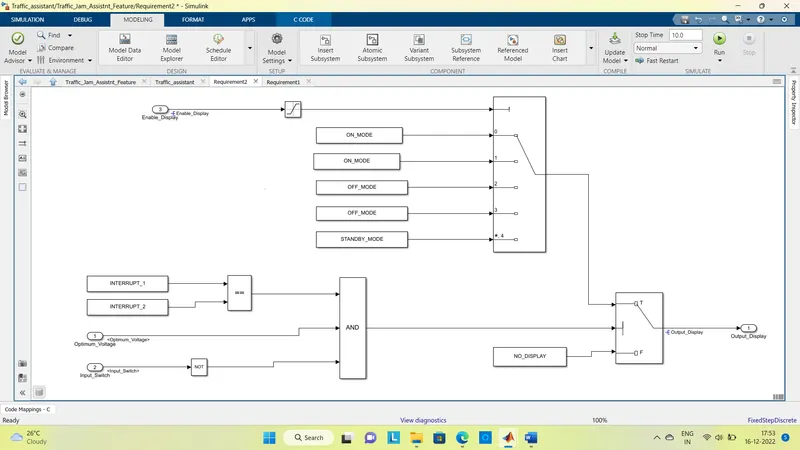
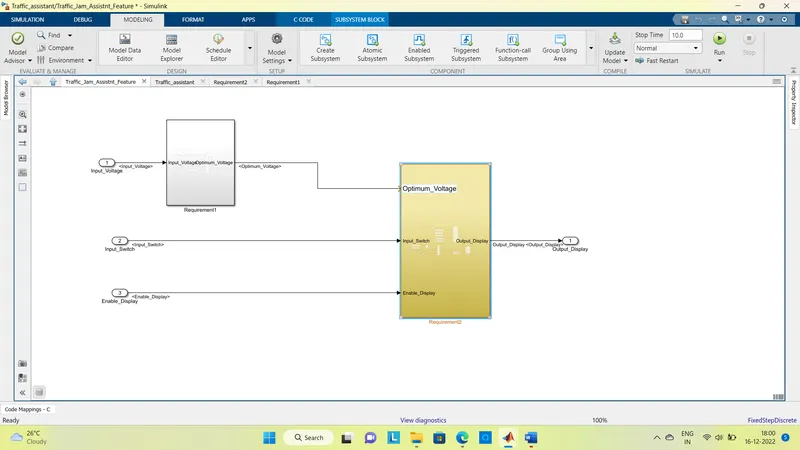
Requirement2 :
- Optimum_Voltage from the Reql , " Input_Switch " , and " Enable_Display " are the Input Signals . The output signal from the subsystem is " Output_Display " .
- Signal " Enable_Display " must be saturated between the range 0 - 7 .
- Input Signal " Enable_Display ' is compared against a pre - defined set of values in a multiport switch . The total data ports in the multiport switch are 5 . Multiport switch inputs 1 & 2 are connected to calibration signal " ON_MODE " , Multiport switch inputs 3 & 4 are connected to calibration signal " OFF_MODE " while Multiport switch input 5 is connected to calibration signal " STANDBY_MODE " . The output from the Multiport switch is connected to the first input port of the Switch block . The third input port of the Switch block is connected to the calibration signal " NO_DISPLAY " .
- Meanwhile NOT the value of the input signal " Input_Switch " is compared in an AND gate against the input signal " Optimum_Voltage " and the output from comparing if calibration signals " INTERRUPT_1 " & " INTERRUPT_2 " are equal . The output of the AND gate is the second input of the switch block .
- The output from the switch block is " Output_Display " .
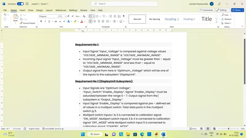
Requirement Tagging :
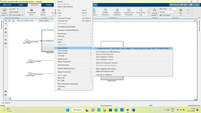
- Requirements can be a tag to requirement 1 & requirement 2 to their corresponding subsystems with word files.
Model Advisor Check :
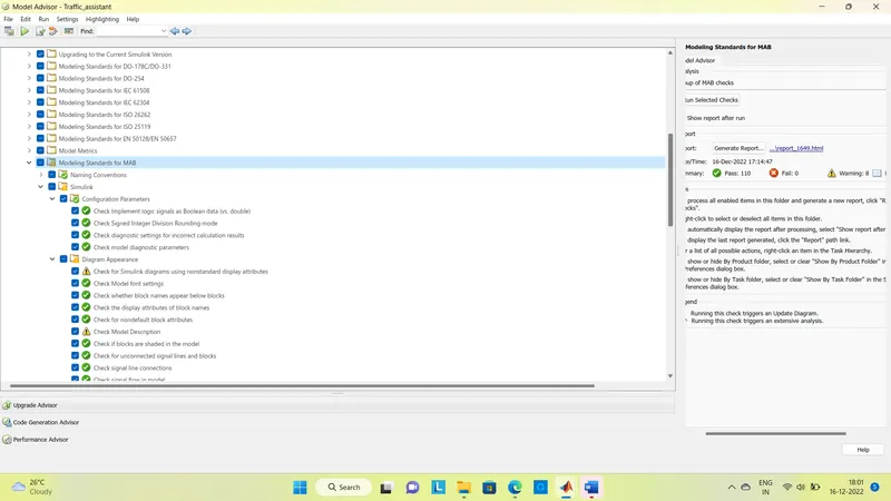
- Model Advisor Check on Modelling Standards for MAAB .
- Model Advisor Check completed with 8 warning and 110 check passed.
- There are warinings that are acceptable but the notable part is that there is not a single failed result.
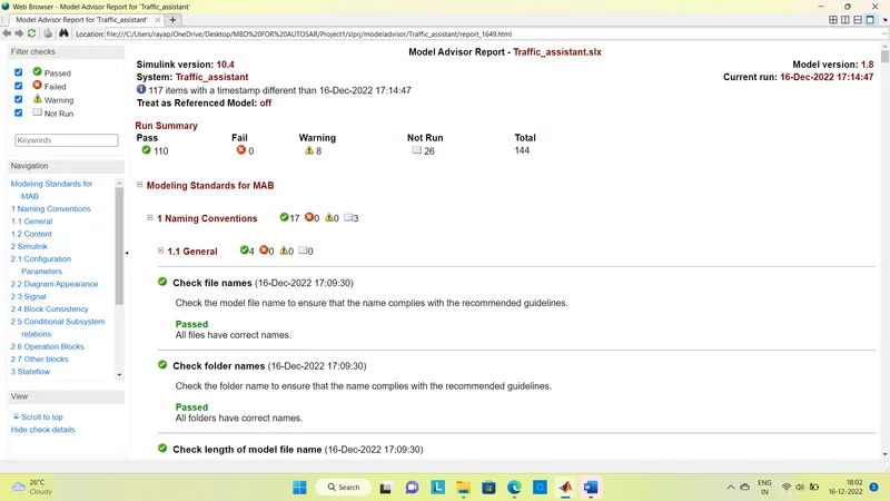
Model Advisor Report :
- Model Advisor Report can be generated,we can choose the format HTML,PDF or Word Format.
- HTML Report is generated and saved in the directory.
Code generation :
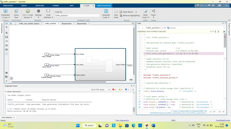
- By using the embedded coder app we can generate code and build our model.
- Successfully conducted model build and generated code . The generated codes and files can be seen in the current directory .
Conclusion :
Developed a model of single feature of Traffice Jam Assist as per MAAB Guidelines as well as created Simulink Data Dictionary using MATLAB & Simulink.Generated a code using Embedde Coder and generated a Model Advisor Report.