Project 1- Traffic Jam Assistant Feature
Aim:
To develop one specific requirement of Traffic Jam Assistant algorithm which would predominantly feature in the IPC algorithm.
Objective:
- This model must be developed in MATLAB Simulink as per MBD guidelines.
- Code Generation Profile must be in Embedded Coder.
- Simulink Data Dictionary must be created for the model & must be linked to the model.
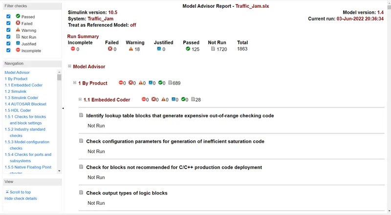
- Model Advisor Report is mandatory & this will be followed by Code Generation.
Theory:
Traffic Jam Assistance Feature:
Traffic Jam Assistance is an active safety system as part of the comprehensive range of intelligent assistance systems. These so-called Advanced Driver Assistance Systems (ADAS).
These Car Pilot safety systems warn the driver of potential hazards and even intervene if necessary. Think of Lane Keep Assistance, Rear Traffic Alert, Blind Spot Monitoring, Drowsiness Warning System and Front Collision Warning with Automatic Emergency Braking. The purpose of this is to make driving easier, more enjoyable and above all, safer. But Car Pilot also includes driver assistance systems which partly take over driving, like Traffic Jam Assistance.
Working:
Traffic Jam Assistance (TJA) is an advanced driver assistance system that continuously measures the speed of the surrounding vehicles when Adaptive Cruise Control is switched on. That speed is compared with your own driving speed. If Traffic Jam Assistance detects many surrounding vehicles at speeds below 60 km/h – and you are therefore very likely to be in a traffic jam – the driver can activate Traffic Jam Assistance. With this, your car partly takes over the driving.
With Traffic Jam Assistance switched on, the car automatically follows the vehicle in front. It accelerates and brakes all by itself, at all speeds below 60 km/h to a standstill and further. In addition, the intelligent technology continuously keeps the distance you set to the vehicle in front of you. But there is more: with Traffic Jam Assistance, your car also steers automatically to stay neatly in the middle of the lane. Even in gentle corners! Very comfortable, carefree and safe driving, regardless the visibility, the weather conditions and the amount of traffic on the road.
Model Development:
Signal and calibration data:
Input Signals:
|
Name of the Signal |
Data Type |
Range |
|
Input_Voltage |
uint8 |
0 - 255 |
|
Input_Switch |
boolean |
0 – 1 |
|
Enable_Display |
uint8 |
0 - 255 |
Output Signal:
|
Name of the Signal |
Data Type |
Range |
|
Output_Display |
uint8 |
0 - 255 |
Calibration Signals:
|
Name of the Signal |
Data Type |
Range |
Initial Value |
|
VOLTAGE_MINIMUM_RANGE |
uint8 |
0 – 255 |
30 |
|
VOLTAGE_MAXIMUM_RANGE |
uint8 |
0 – 255 |
50 |
|
OFF_MODE |
uint8 |
0 – 255 |
2 |
|
ON_MODE |
uint8 |
0 – 255 |
1 |
|
STANDBY_MODE |
uint8 |
0 – 255 |
3 |
|
INTERRUPT_1 |
boolean |
0 – 1 |
1 |
|
INTERRUPT_2 |
boolean |
0 - 1 |
1 |
|
NO_DISPLAY |
uint8 |
0 – 255 |
0 |
Local Signal:
|
Name of the Signal |
Data Type |
Range |
|
Optimum_Voltage |
boolean |
0 - 1 |
Requirement No 1:
- Input Signal “Input_Voltage” is compared against voltage values “VOLTAGE_MINIMUM_RANGE” & “VOLTAGE_MAXIMUM_RANGE”.
- Incoming input signal “Input_Voltage” must be greater than – equal to “VOLTAGE_MINIMUM_RANGE” and less than – equal to “VOLTAGE_MAXIMUM_RANGE”.
- Output signal from here is “Optimum_Voltage” which will be one of the inputs to the subsystem “DisplayUnit”.
Requirement No 2 (DisplayUnit Subsystem):
- Input Signals are “Optimum_Voltage”, “Input_Switch”,“Enable_Display”. Signal “Enable_Display” must be saturated between the range 0 – 7. Output signal from the subsystem is “Output_Display”.
- Input Signal “Enable_Display” is compared against pre – defined set of values in a multiport switch. Total data ports in the multiport switch is 5.
- Multiport switch inputs 1 & 2 is connected to calibration signal “ON_MODE”, Multiport switch inputs 3 & 4 is connected to calibration signal “OFF_MODE” while Multiport switch input 5 is connected to calibration signal “STANDBY_MODE”.
- The output from Multiport switch is connected to the first input port of the Switch block. The third input port of the Switch block is connected to the calibration signal “NO_DISPLAY”.
- Meanwhile NOT value of input signal “Input_Switch” is compared in an AND gate against input signal “Optimum_Voltage” and the output from comparing if calibration signals “INTERRUPT_1” & “INTERRUPT_2” are equal. The output of the AND gate is the second input of the switch block.
- The output from the switch block is “Output_Display”.
Data Dictionary Creation:
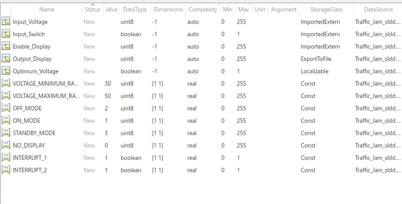
- A new simulink data dictionary data dictionary is created and updated signals & calibratiion data list as per our requirements.
- The first thing that will do is to create a SLDD using the given Signal & Calibration data list.
The following SLDD file is:
Solver Configuration parameter:
- Solver type: Fixed
- Solver : Discrete (no continuous states)
- Sample time: 0.01
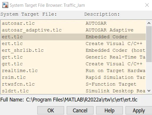
Code Generation Parameters:
- System target file: ert.tlc (Embeded coder)
Designing MATLAB Simulink Model:
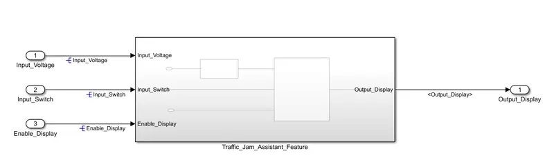
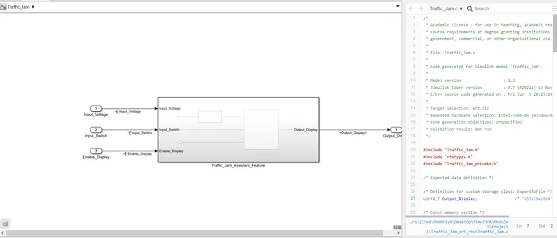
- The Input Voltage, input switch & the enable switch are the inputs to the system, & the output. Display is the final output from the system.
Requirement 1:
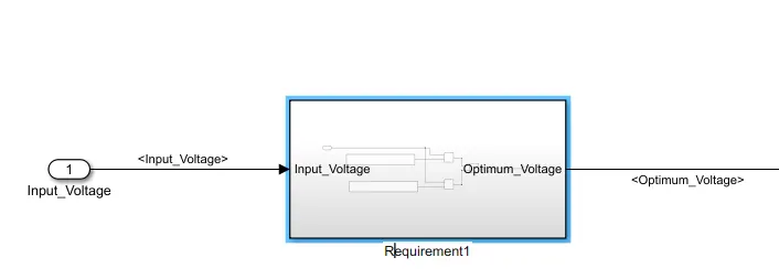
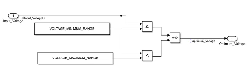
- Input Signal “Input_Voltage” is compared against voltage values “VOLTAGE_MINIMUM_RANGE” & “VOLTAGE_MAXIMUM_RANGE”.
- Then their outputs are given as the input for AND block, the output of which is Optimum_Voltage.
Requirement 2:
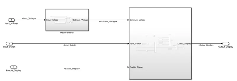
- Input Signals are “Optimum_Voltage”, “Input_Switch”,“Enable_Display”. Output signal from the subsystem is “Output_Display”.
- Signal “Enable_Display” must be saturated between the range 0 – 7.
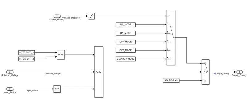
- Input Signal “Enable_Display” is compared against pre – defined set of values in a multiport switch. Total data ports in the multiport switch is 5.
- Multiport switch inputs 1 & 2 is connected to calibration signal “ON_MODE”, Multiport switch inputs 3 & 4 is connected to calibration signal “OFF_MODE” while Multiport switch input 5 is connected to calibration signal “STANDBY_MODE”.
- The output from Multiport switch is connected to the first input port of the Switch block. The third input port of the Switch block is connected to the calibration signal “NO_DISPLAY”.
- Meanwhile NOT value of input signal “Input_Switch” is compared in an AND gate against input signal “Optimum_Voltage” and the output from comparing if calibration signals “INTERRUPT_1” & “INTERRUPT_2” are equal. The output of the AND gate is the second input of the switch block.
- The output from the switch block is “Output_Display”.
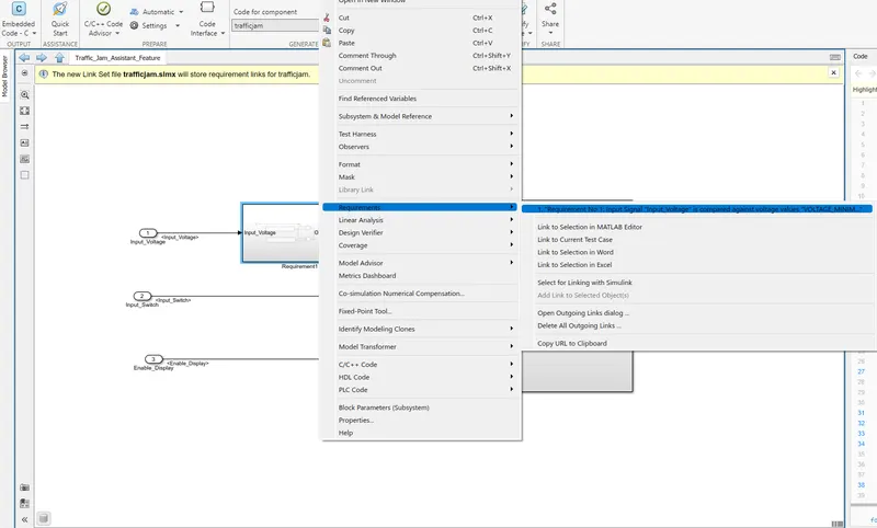
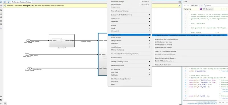
Requirement Tagging:
Requirement can be a tag to requirement 1 & requirement 2 to their corresponding subsystems with word files.
Code Generation:
- By using the embeded coder app we can generate code and build our model.
Code:
/*
 * Academic License - for use in teaching, academic research, and meeting
 * course requirements at degree granting institutions only.  Not for
 * government, commercial, or other organizational use.
 *
 * File: Traffic_Jam.c
 *
 * Code generated for Simulink model 'Traffic_Jam'.
 *
 * Model version                  : 1.3
 * Simulink Coder version         : 9.7 (R2022a) 13-Nov-2021
 * C/C++ source code generated on : Fri Jun  3 20:25:29 2022
 *
 * Target selection: ert.tlc
 * Embedded hardware selection: Intel->x86-64 (Windows64)
 * Code generation objectives: Unspecified
 * Validation result: Not run
 */

#include "Traffic_Jam.h"
#include "rtwtypes.h"
#include "Traffic_Jam_private.h"

/* Exported data definition */

/* Definition for custom storage class: ExportToFile */
uint8_T Output_Display;                /* '/Switch' */

/* Const memory section */
/* Definition for custom storage class: Const */
const boolean_T INTERRUPT_1 = true;    /* Referenced by: '/Constant6' */
const boolean_T INTERRUPT_2 = true;    /* Referenced by: '/Constant7' */
const uint8_T NO_DISPLAY = 0U;         /* Referenced by: '/Constant5' */
const uint8_T OFF_MODE = 2U;           /* Referenced by:
                                        * '/Constant2'
                                        * '/Constant3'
                                        */
const uint8_T ON_MODE = 1U;            /* Referenced by:
                                        * '/Constant'
                                        * '/Constant1'
                                        */
const uint8_T STANDBY_MODE = 3U;       /* Referenced by: '/Constant4' */
const uint8_T VOLTAGE_MAXIMUM_RANGE = 50U;/* Referenced by: '/Constant' */
const uint8_T VOLTAGE_MINIMUM_RANGE = 30U;/* Referenced by: '/Constant1' */

/* Real-time model */
static RT_MODEL_Traffic_Jam_T Traffic_Jam_M_;
RT_MODEL_Traffic_Jam_T *const Traffic_Jam_M = &Traffic_Jam_M_;

/* Model step function */
void Traffic_Jam_step(void)
{
  /* local block i/o variables */
  boolean_T Optimum_Voltage;

  /* Logic: '/Logical Operator' incorporates:
   *  Constant: '/Constant'
   *  Constant: '/Constant1'
   *  Inport: '/Input_Voltage'
   *  RelationalOperator: '/Relational Operator'
   *  RelationalOperator: '/Relational Operator1'
   */
  Optimum_Voltage = ((Input_Voltage >= VOLTAGE_MINIMUM_RANGE) && (Input_Voltage <=
    VOLTAGE_MAXIMUM_RANGE));

  /* Switch: '/Switch' incorporates:
   *  Constant: '/Constant6'
   *  Constant: '/Constant7'
   *  Inport: '/Input_Switch'
   *  Logic: '/Logical Operator'
   *  Logic: '/Logical Operator1'
   *  RelationalOperator: '/Relational Operator'
   */
  if ((INTERRUPT_1 == INTERRUPT_2) && Optimum_Voltage && (!Input_Switch)) {
    uint8_T tmp;

    /* Saturate: '/Saturation' incorporates:
     *  Inport: '/Enable_Display'
     */
    if (Enable_Display <= 7) {
      tmp = Enable_Display;
    } else {
      tmp = 7U;
    }

    /* End of Saturate: '/Saturation' */

    /* MultiPortSwitch: '/Multiport Switch' */
    switch (tmp) {
     case 0:
      /* Switch: '/Switch' incorporates:
       *  Constant: '/Constant'
       */
      Output_Display = ON_MODE;
      break;

     case 1:
      /* Switch: '/Switch' incorporates:
       *  Constant: '/Constant1'
       */
      Output_Display = ON_MODE;
      break;

     case 2:
      /* Switch: '/Switch' incorporates:
       *  Constant: '/Constant2'
       */
      Output_Display = OFF_MODE;
      break;

     case 3:
      /* Switch: '/Switch' incorporates:
       *  Constant: '/Constant3'
       */
      Output_Display = OFF_MODE;
      break;

     default:
      /* Switch: '/Switch' incorporates:
       *  Constant: '/Constant4'
       */
      Output_Display = STANDBY_MODE;
      break;
    }

    /* End of MultiPortSwitch: '/Multiport Switch' */
  } else {
    /* Switch: '/Switch' incorporates:
     *  Constant: '/Constant5'
     */
    Output_Display = NO_DISPLAY;
  }

  /* End of Switch: '/Switch' */
}

/* Model initialize function */
void Traffic_Jam_initialize(void)
{
  /* (no initialization code required) */
}

/* Model terminate function */
void Traffic_Jam_terminate(void)
{
  /* (no terminate code required) */
}

/*
 * File trailer for generated code.
Code Generation Report:
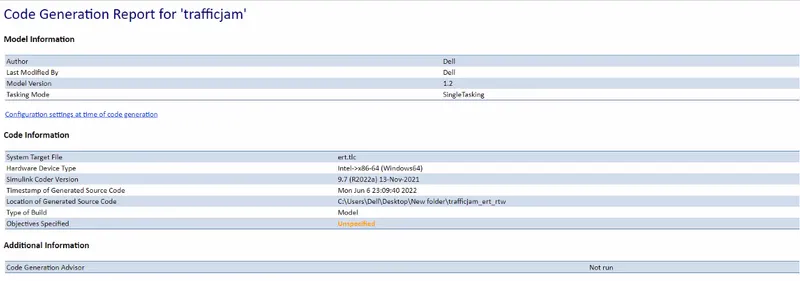
- Succesfully conducted model build & generated code. the generated codes and files can be seen in the current dictionary.
Model Advisory ChecK:'
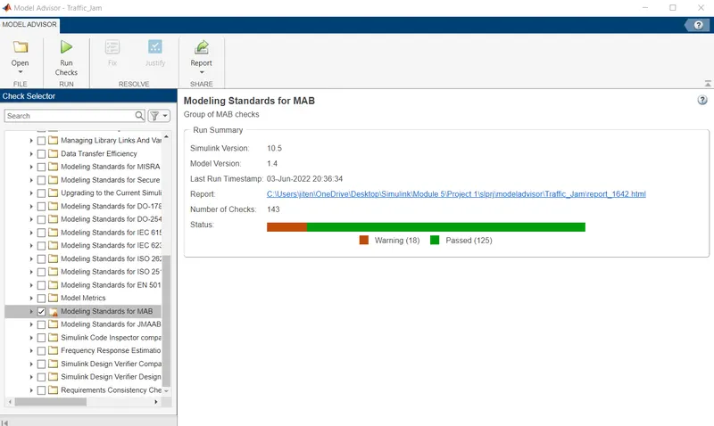
- Model advisor check on modelling standards for MAAB.
Model Advisor Report:
- Model advisor report can be generated, we can choose the format HTML, PDF or word format.
Conclusion:
Developed a model of a single feature of Traffic Jam Assistant as per MAAB guidelenes as well as created simulink data dictionary using MATLAB & Simulink. Generated a code using embeded coder & generated a model advisor report.