Project 1- Traffic Jam Assistant Feature
Ans:
1)Creating MATLAB Model:-
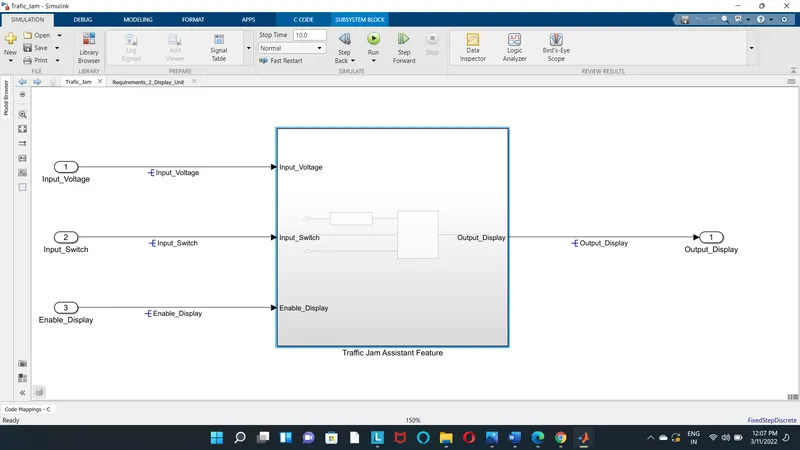
This is the main model subsystem that has three inputs Input_Voltage, Input_Switch and Enable_Display entering into
Traffic_Jam_Assistant_Feature the subsystem and one output Output_Display
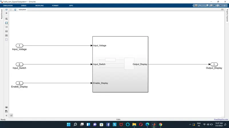
There are two requirment or two subsystem designed inside the mail model
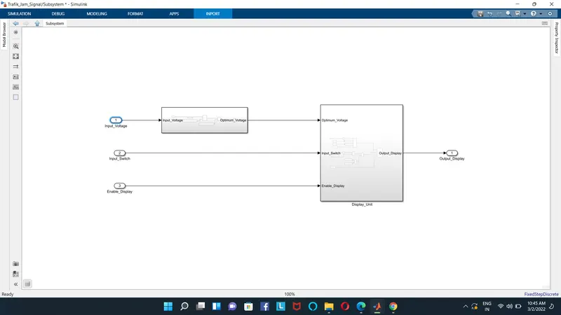
Requirement No 1:
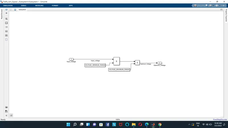
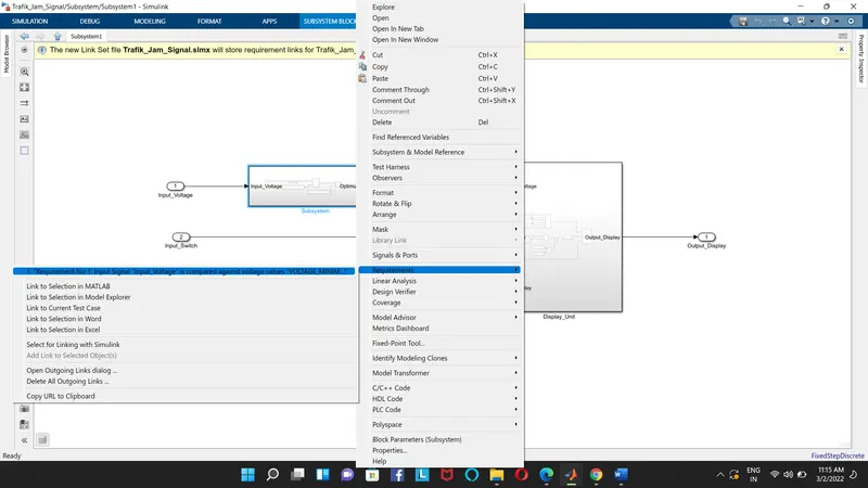
-Input Signal “Input_Voltage” is compared against voltage values “VOLTAGE_MINIMUM_RANGE” & “VOLTAGE_MAXIMUM_RANGE”.
-Incoming input signal “Input_Voltage” must be greater than – equal to “VOLTAGE_MINIMUM_RANGE” and less than – equal to
“VOLTAGE_MAXIMUM_RANGE”.
-Output signal from here is “Optimum_Voltage” which will be one of the inputs to the subsystem “DisplayUnit”
Requirement No 2 (DisplayUnit Subsystem):
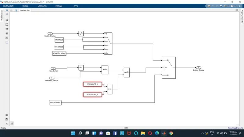
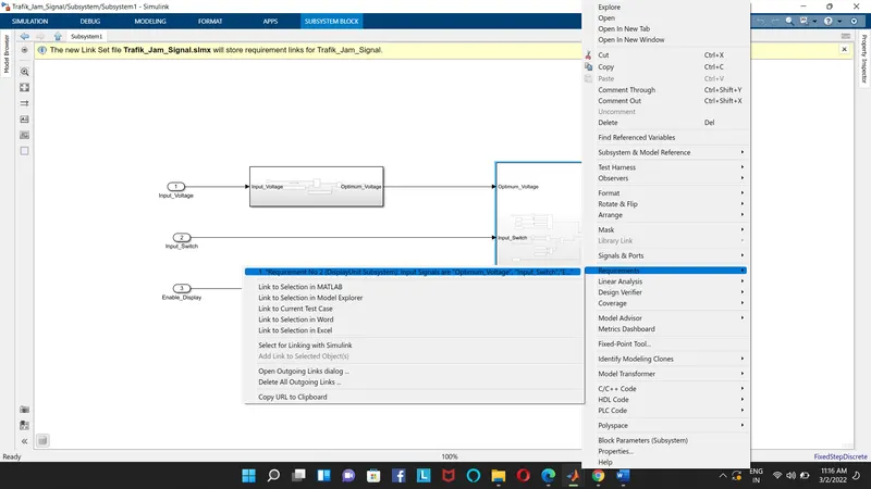
-Input Signals are “Optimum_Voltage”, “Input_Switch”,“Enable_Display”. Signal “Enable_Display” must be saturated between the range 0 – 7.Output signal from the subsystem is “Output_Display”.
-Input Signal “Enable_Display” is compared against pre – defined set of values in a multiport switch. Total data ports in the multiport switch
is 5.
-Multiport switch inputs 1 & 2 is connected to calibration signal “ON_MODE”, Multiport switch inputs 3 & 4 is connected to calibration signal
“OFF_MODE” while Multiport switch input 5 is connected to calibration signal “STANDBY_MODE”.
-The output from Multiport switch is connected to the first input port of the Switch block. The third input port of the Switch block is
connected to the calibration signal “NO_DISPLAY”.
-Meanwhile NOT value of input signal “Input_Switch” is compared in an AND gate against input signal “Optimum_Voltage” and the output
from comparing if calibration signals “INTERRUPT_1” & “INTERRUPT_2” are equal. The output of the AND gate is the second input of the
switch block.
-The output from the switch block is “Output_Display
2)Requirement Tagging:-
3)Developing SLDD:-
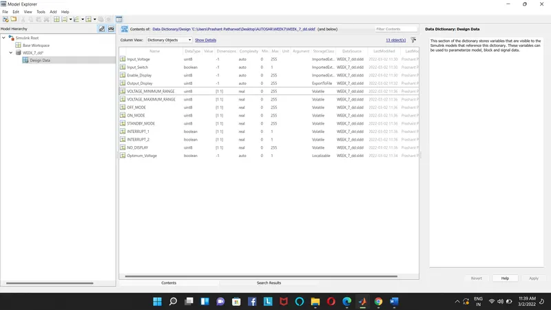
All the inputs, outputs, calibration parameters are saved in SLDD so while simulation the model takes all the values and its parameters from the Simulink Data Dictionary
4) Signal Resolution for inputs and outputs:-
the inputs and output signals are resolved so the signals will take the values from sldd and pass them to the logical blocks. Otherwise, it may
take some junk values if it is unresolved
5) Model Update:-
The model update is done by Ctrl-D. this is done to check for any static errors. If there are no errors coming the model is working fine without any errors.
6)Simulation:-
The model is simulated too for checking for errors and warnings
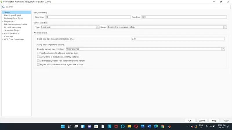
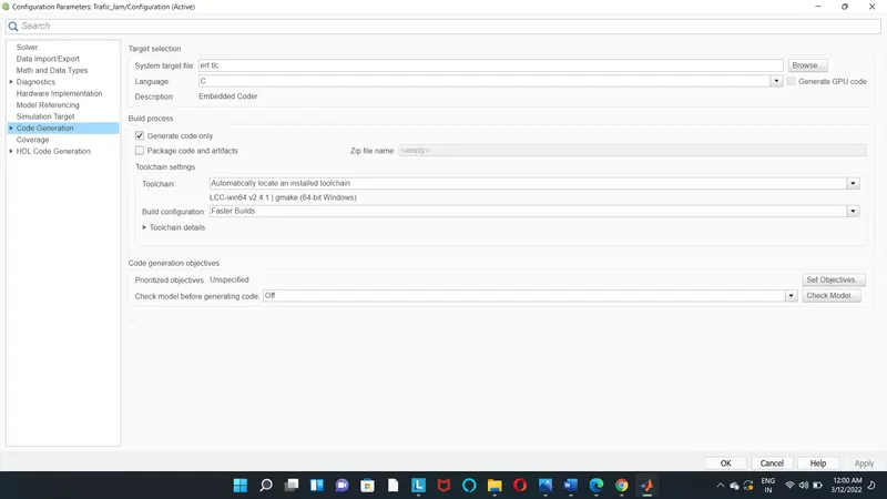
7) Configuration Parameter Update:-
Various configuration parameters are updated as per the code generation the solver type should be fixed for code generation
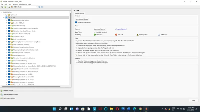
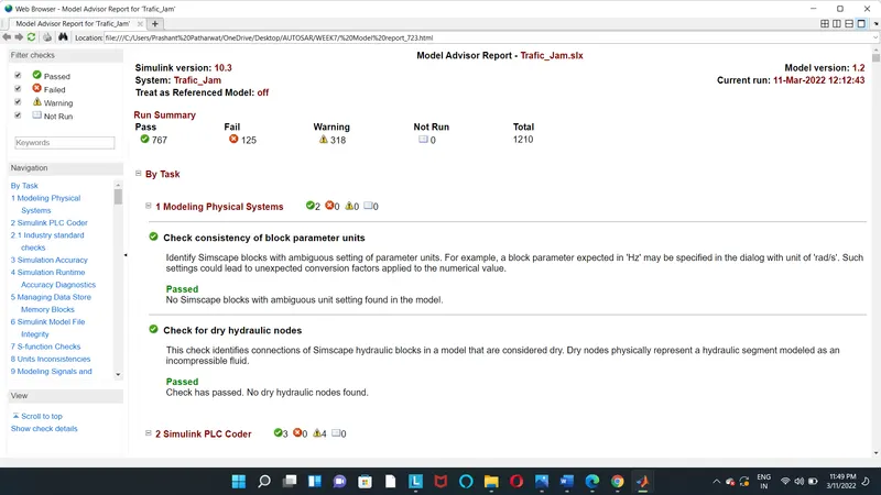
8)Model Advisory Report:-
By running the model advisor tool, we can see commonly made modelling errors.
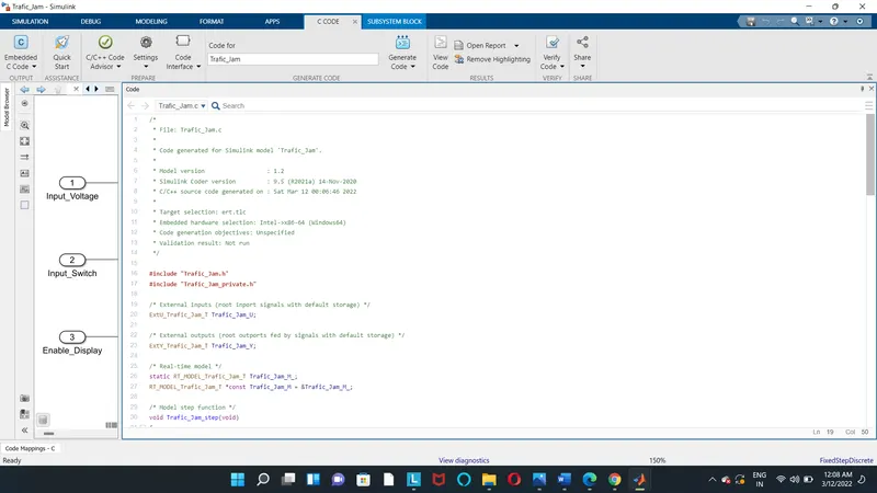
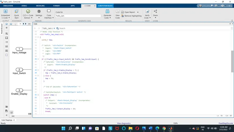
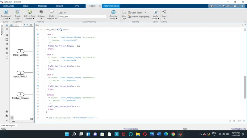
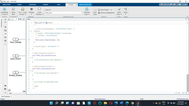
9) Code generation :-
build a model for generating code
Conclusion:
Thus for the above project, Simulink Data Dictionary has been created, and Model Advisor Report also created and done with verification and
Generation of code.