Project 1- Traffic Jam Assistant Feature
AIM:
To develop a specific requirement of Traffic Jam Assistant algorithm which would predominantly feature in the IPC algorithm.
-The given signal parameters are as follows:
Input Signals:
|
Name of the Signal |
Data Type |
Range |
|
Input_Voltage |
uint8 |
0 - 255 |
|
Input_Switch |
boolean |
0 – 1 |
|
Enable_Display |
uint8 |
0 - 255 |
Output Signal:
|
Name of the Signal |
Data Type |
Range |
|
Output_Display |
uint8 |
0 - 255 |
Calibration Signals:
|
Name of the Signal |
Data Type |
Range |
Initial Value |
|
VOLTAGE_MINIMUM_RANGE |
uint8 |
0 – 255 |
30 |
|
VOLTAGE_MAXIMUM_RANGE |
uint8 |
0 – 255 |
50 |
|
OFF_MODE |
uint8 |
0 – 255 |
2 |
|
ON_MODE |
uint8 |
0 – 255 |
1 |
|
STANDBY_MODE |
uint8 |
0 – 255 |
3 |
|
INTERRUPT_1 |
boolean |
0 – 1 |
1 |
|
INTERRUPT_2 |
boolean |
0 - 1 |
1 |
|
NO_DISPLAY |
uint8 |
0 – 255 |
0 |
Local Signal:
|
Name of the Signal |
Data Type |
Range |
|
Optimum_Voltage |
boolean |
0 - 1 |
-The requirement condition is given as below:
Requirement No 1:
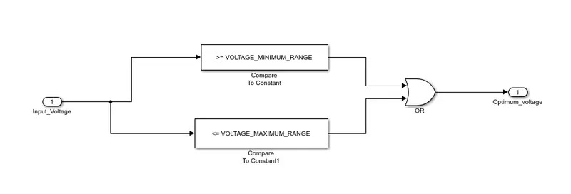
- Input Signal “Input_Voltage” is compared against voltage values “VOLTAGE_MINIMUM_RANGE” & “VOLTAGE_MAXIMUM_RANGE”.
- Incoming input signal “Input_Voltage” must be greater than – equal to “VOLTAGE_MINIMUM_RANGE” and less than – equal to “VOLTAGE_MAXIMUM_RANGE”.
- Output signal from here is “Optimum_Voltage” which will be one of the inputs to the subsystem “DisplayUnit”.
Requirement No 2 (DisplayUnit Subsystem):
- Input Signals are “Optimum_Voltage”, “Input_Switch”,“Enable_Display”. Signal “Enable_Display” must be saturated between the range 0 – 7. Output signal from the subsystem is “Output_Display”.
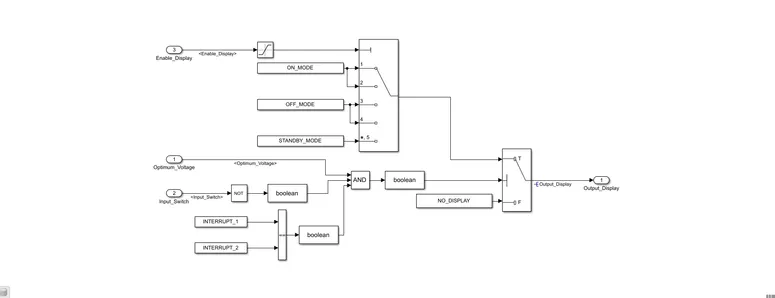
- Input Signal “Enable_Display” is compared against pre – defined set of values in a multiport switch. Total data ports in the multiport switch is 5.
- Multiport switch inputs 1 & 2 is connected to calibration signal “ON_MODE”, Multiport switch inputs 3 & 4 is connected to calibration signal “OFF_MODE” while Multiport switch input 5 is connected to calibration signal “STANDBY_MODE”.
- The output from Multiport switch is connected to the first input port of the Switch block. The third input port of the Switch block is connected to the calibration signal “NO_DISPLAY”.
- Meanwhile NOT value of input signal “Input_Switch” is compared in an AND gate against input signal “Optimum_Voltage” and the output from comparing if calibration signals “INTERRUPT_1” & “INTERRUPT_2” are equal. The output of the AND gate is the second input of the switch block.
- The output from the switch block is “Output_Display”.
Solution:
To create the traffic jam assistance model in simulink model we need to follow the steps below.
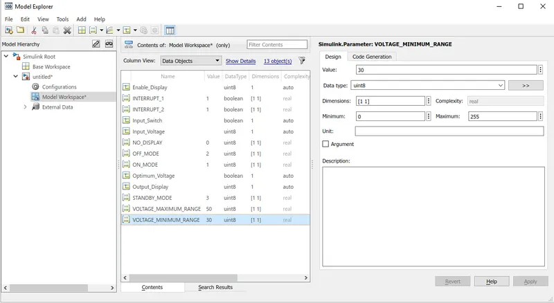
Step1:To create a simulink data dictionary with given input,output and calibration signal.
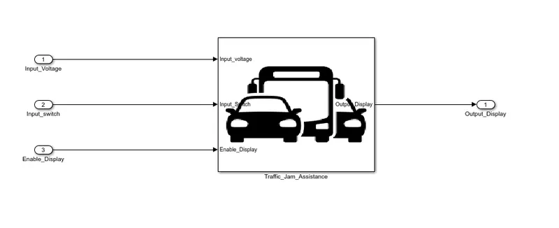
Step2:Now we develop the subsystem for Traffic jam assistance with three inputs and an output.
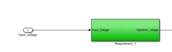
Step3:Now we develop a subsystem for Requirement 1:
Inside Requirement susbsystem we have attached the following blocks as per the requirements,
Step 4:To develop a Display unit subsystem for Requirement 2
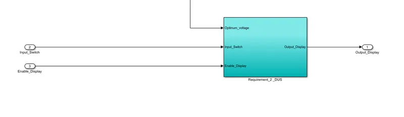
Inside the subsystem we have arranged the blocks as per our requirement,
Model Advisor Check for MAB guidelines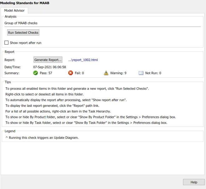
Code generated:
/*
 * File: Traffic_jam.c
 *
 * Code generated for Simulink model 'Traffic_jam'.
 *
 * Model version                  : 1.3
 * Simulink Coder version         : 8.14 (R2018a) 14-september-2020
 * C/C++ source code generated on : Tue Sep 07 06:06:58 2021
 *
 * Target selection: ert.tlc
 * Embedded hardware selection: Intel->x86-64 (Windows64)
 * Code generation objectives: Unspecified
 * Validation result: Not run
 */

#include "Traffic_jam_Assistance.h"
#include "Traffic_jam_Assistance_private.h"

/* Real-time model */
static RT_MODEL_Traffic_jam_Assistance_T Traffic_jam_Assistance_M_;
RT_MODEL_Traffic_jam_Assistance_T *const Traffic_jam_Assistance_M = &Traffic_jam_Assistance_M_;

/* Model step function */
void Traffic_jam_Assistance_step(void)
{
  /* local block i/o variables */
  boolean_T Optimum_Voltage;
  uint8_T tmp;

  /* Outputs for Atomic SubSystem: '<Root>/Traffic_jam_assistance' */
  /* Logic: '<S3>/OR' incorporates:
   *  Constant: '<S4>/Constant'
   *  Constant: '<S5>/Constant'
   *  Inport: '<Root>/Input_Voltage'
   *  RelationalOperator: '<S4>/Compare'
   *  RelationalOperator: '<S5>/Compare'
   */
  Optimum_Voltage = ((Input_Voltage >= VOLTAGE_MINIMUM_RANGE) || (Input_Voltage <=
    VOLTAGE_MAXIMUM_RANGE));

  /* Switch: '<S2>/Switch' incorporates:
   *  Constant: '<S2>/Constant4'
   *  Constant: '<S2>/Constant5'
   *  Inport: '<Root>/Input_Switch'
   *  Logic: '<S2>/AND'
   *  Logic: '<S2>/NOT'
   *  RelationalOperator: '<S2>/Equal'
   */
  if (Optimum_Voltage && (!Input_Switch) && (INTERRUPT_1 == INTERRUPT_2)) {
    /* Saturate: '<S2>/Saturation' incorporates:
     *  Inport: '<Root>/Enable_Display'
     */
    if (Enable_Display < 1) {
      tmp = 0U;
    } else {
      tmp = 1U;
    }

    /* End of Saturate: '<S2>/Saturation' */

    /* MultiPortSwitch: '<S2>/Multiport Switch' */
    if (tmp == 1) {
      /* Switch: '<S2>/Switch' incorporates:
       *  Constant: '<S2>/Constant'
       */
      Output_Display = ON_MODE;
    } else {
      /* Switch: '<S2>/Switch' incorporates:
       *  Constant: '<S2>/Constant1'
       */
      Output_Display = STANDBY_MODE;
    }

    /* End of MultiPortSwitch: '<S2>/Multiport Switch' */
  } else {
    /* Switch: '<S2>/Switch' incorporates:
     *  Constant: '<S2>/Constant3'
     */
    Output_Display = NO_DISPLAY;
  }

  /* End of Switch: '<S2>/Switch' */
  /* End of Outputs for SubSystem: '<Root>/Traffic_jam_Assistance' */
}

/* Model initialize function */
void Traffic_jam_Assistance_initialize(void)
{
  /* (no initialization code required) */
}

/* Model terminate function */
void Traffic_jam_Assistance_terminate(void)
{
  /* (no terminate code required) */
}

/*
 * File trailer for generated code.
 *
 * [EOF]
 */
Conclusion:
The model was build and sucessfuly runned based on the requirement.Model Advisory was checked and report code was generated.