Project-1: Powertrain for aircraft in runways
1. Search and list out the total weight of various types of aircrafts.
ans:
The total weight of various types of aircraft can vary significantly depending on their size, purpose, and design. Here's a list of the approximate maximum takeoff weights (MTOW) for different categories of aircraft as of my last knowledge update in September 2021. Keep in mind that these weights can change with newer models and modifications:
1. Light Aircraft:
- Single-Engine Piston Aircraft: Typically around 1,000 to 3,000 pounds (450 to 1,360 kilograms).
2. General Aviation and Business Jets:
- Light Business Jets: Approximately 5,000 to 15,000 pounds (2,270 to 6,800 kilograms).
- Medium Business Jets: Roughly 15,000 to 30,000 pounds (6,800 to 13,600 kilograms).
3. Commercial Aircraft:
- Regional Jets: Between 30,000 to 100,000 pounds (13,600 to 45,360 kilograms).
- Narrow-Body Aircraft (e.g., Boeing 737, Airbus A320): About 100,000 to 200,000 pounds (45,360 to 90,720 kilograms).
- Wide-Body Aircraft (e.g., Boeing 777, Airbus A350): Typically 200,000 to 1,000,000 pounds (90,720 to 453,600 kilograms) or more.
4. Cargo Aircraft:
- Cargo versions of commercial aircraft can have higher maximum takeoff weights, often exceeding 1,000,000 pounds (453,600 kilograms).
5. Military Aircraft:
- Fighter Jets: Generally range from 20,000 to 70,000 pounds (9,070 to 31,750 kilograms) depending on the type.
- Military Transport Aircraft (e.g., C-130 Hercules, C-17 Globemaster): Vary widely from 150,000 to over 600,000 pounds (68,040 to 272,160 kilograms).
6. Helicopters:
- Small Helicopters: Typically 1,000 to 5,000 pounds (450 to 2,270 kilograms).
- Medium-Lift Helicopters (e.g., Sikorsky UH-60 Black Hawk): About 10,000 to 22,000 pounds (4,540 to 9,980 kilograms).
- Heavy-Lift Helicopters (e.g., Boeing CH-47 Chinook): Approximately 25,000 to 54,000 pounds (11,340 to 24,490 kilograms).
7. Unmanned Aerial Vehicles (UAVs) and Drones:
- Weights vary widely from a few pounds to several tons, depending on the UAV's size and purpose.
In aircraft design and engineering, the weight distribution of an aircraft is a critical consideration for ensuring stability and safety during flight. One of the key aspects of weight distribution is the allocation of weight to various compartments within the aircraft. These compartments are often referred to as "stations" or "zones." Here's an overview of some common compartments or stations found in aircraft:
1. Nose Compartment (Station 0):This is the area at the very front of the aircraft, often housing the radar equipment, avionics, and sometimes a crew rest area. The weight in this compartment contributes to the aircraft's forward weight distribution.
2. Cockpit Compartment: The cockpit is the area where the flight crew (pilots) operate the aircraft. It includes seats, controls, avionics, and instrumentation. The weight of the crew, their seats, and associated equipment is accounted for in this compartment.
3. Passenger Compartment: In commercial aircraft, this is where passengers are seated. The weight of seats, passengers, and their carry-on baggage is distributed throughout this compartment. It is crucial to balance the passenger load to maintain the aircraft's center of gravity within safe limits.
4. Cargo Compartment: Cargo aircraft and some commercial aircraft have dedicated cargo compartments. The weight of cargo, freight containers, and luggage is concentrated in this area. The distribution of cargo is carefully calculated to maintain proper weight and balance.
5. Fuel Tanks: Fuel is one of the most critical components in aircraft weight distribution. The aircraft's fuel is stored in various tanks throughout the wings, fuselage, and sometimes the tail. As fuel is consumed during the flight, the aircraft's weight and balance change accordingly.
6. Aft Compartment: Located toward the rear of the aircraft, this compartment may house additional cargo, avionics equipment, or other systems. The weight in this compartment affects the aircraft's aft weight distribution.
7. Empennage (Tail Section): The tail section of the aircraft houses the horizontal and vertical stabilizers, as well as the tail cone. Weight in this area can significantly impact the aircraft's tail-heavy or tail-light characteristics, which can affect stability.
8.Wing Sections: The wings of an aircraft are designed to carry a significant portion of the aircraft's weight, including fuel. Fuel is stored in wing tanks, and the distribution of fuel across the wings is closely monitored to maintain proper lateral balance.
The aircraft performance and weight characteristics. Let's briefly define each of them:
1. Aircraft Gross Weight:This is the total weight of the aircraft, including everything on board—passengers, cargo, fuel, and the aircraft itself. It's the weight of the aircraft at any given moment.
2. Maximum Ramp Weight:The maximum weight an aircraft can have when it's on the ground, including all passengers, cargo, and fuel. It might be higher than the maximum takeoff weight to account for fuel burn during taxi.
3. Maximum Takeoff Weight (MTOW):This is the maximum weight at which an aircraft can safely take off. It includes the aircraft's operating weight, passengers, cargo, and the necessary fuel.
4. Manufacturers Empty Weight: This is the weight of the aircraft when it's in a "brand new" condition, including all standard equipment, but without any fuel, passengers, or optional equipment.
5. Operating Empty Weight (OEW): This is the weight of the aircraft in its current operating condition, including standard equipment, oil, and other necessary fluids but without passengers or cargo. It's essentially the manufacturer's empty weight plus the weight of the fluids.
6. Zero Fuel Weight (ZFW): This is the weight of the aircraft without any fuel. It includes the operating empty weight plus the weight of passengers and cargo. ZFW is important for weight and balance calculations because it affects the aircraft's CG.
These terms are essential for flight planning, aircraft performance calculations, and ensuring the safety and efficiency of aircraft operations. Specific values for V-speeds, weight limits, and performance characteristics are provided in an aircraft's operating manual and performance charts, which are used by pilots and flight planners to make informed decisions during flight.
2. Is there any difference between ground speed and air speed?
ans:
Ground Speed:
Ground speed, often abbreviated as GS, is the actual speed of an aircraft relative to the Earth's surface. It takes into account both the aircraft's true airspeed (TAS) and the effect of winds blowing over the ground. Here are some key points about ground speed:
1. Calculation of Ground Speed: Ground speed is calculated by combining the aircraft's TAS with the vector sum of the aircraft's motion and the wind's motion. If there is a headwind (wind blowing opposite to the aircraft's direction), ground speed will be lower than TAS. Conversely, if there is a tailwind (wind blowing in the same direction as the aircraft's motion), ground speed will be higher than TAS.
2. Importance of Ground Speed:
- Navigation: Ground speed is crucial for navigation because it tells the pilot the actual rate at which the aircraft is progressing over the Earth's surface. It helps in estimating the time to reach a destination and in determining the track (the direction) over the ground.
- Fuel Efficiency: Ground speed affects fuel consumption. A headwind increases fuel consumption, while a tailwind reduces it, as the aircraft spends more or less time in the air.
- ATC Communications: Air Traffic Control (ATC) often communicates with aircraft based on their ground speed to provide separation and sequencing instructions.
Airspeed:
Airspeed is the speed of an aircraft relative to the air through which it is flying. It is categorized into different types, each serving specific purposes:
1.Indicated Airspeed (IAS):
- IAS is the airspeed displayed on the aircraft's airspeed indicator.
- It is uncorrected for any instrument or installation errors.
- It is primarily used for reference and for maintaining safe speeds during various phases of flight.
2. Calibrated Airspeed (CAS):
- CAS is IAS corrected for instrument and installation errors.
- Manufacturers provide correction tables or charts for CAS, helping pilots obtain more accurate speed indications.
3. True Airspeed (TAS):
- TAS is CAS corrected for variations in air density at altitude.
- As an aircraft climbs to higher altitudes where the air is less dense, TAS becomes greater than CAS at the same power setting.
- TAS is crucial for calculating true performance values, such as true groundspeed and fuel consumption.
4. Groundspeed:
- Groundspeed, as previously mentioned, is TAS corrected for wind effects.
- It is the actual speed at which the aircraft moves over the ground, accounting for headwinds and tailwinds.
- Groundspeed is vital for flight planning, determining the time to reach waypoints, and making adjustments during the flight to stay on schedule.
In summary, ground speed reflects the actual motion of the aircraft over the Earth's surface and considers wind effects, while airspeed measures the speed of the aircraft relative to the air it is moving through. Both ground speed and airspeed are essential for safe and efficient flight, and pilots use them in combination to navigate, calculate fuel consumption, and make real-time decisions during their journeys.
3. Why is it not recommended to use aircraft engine power to move it on the ground at Airport?
ans:
Using aircraft engine power to move an aircraft on the ground at an airport is generally not recommended for several important reasons:
1. Safety Concerns:
- Aircraft engines are extremely powerful and can generate high thrust, which can make ground movement unpredictable and potentially hazardous.
- The abrupt application of engine power on the ground can lead to loss of control, especially in adverse weather conditions, on slippery surfaces, or during taxiing at low speeds.
2. Risk of Damage:
- Using engine power for ground movement can place excessive stress on the landing gear, tires, and other components designed for taxiing, not high-thrust propulsion.
- Taxiing with engine power can lead to tire overheating and wear, potentially resulting in tire blowouts.
3. Fuel Efficiency:
- Taxiing under engine power consumes a significant amount of fuel, which can be costly for airlines and operators, especially at busy airports with long taxi times.
- Aircraft engines are most efficient when they operate at cruising altitudes, so using them for ground movement is not fuel-efficient.
4. Environmental Impact:
- Running aircraft engines on the ground produces emissions and noise, contributing to airport pollution and noise pollution in the vicinity of the airport.
- Many airports have strict regulations and guidelines for minimizing unnecessary engine idling to reduce environmental impact.
5. Wear and Tear:
- Continuous use of engine power for ground movement can result in increased wear and tear on the engines, which can lead to maintenance issues and more frequent engine overhauls.
6. Control and Maneuverability:
- Aircraft are designed with dedicated systems for ground movement, such as nose wheels and steering mechanisms, to provide precise control and maneuverability during taxiing.
- Using engine thrust can make it difficult to steer the aircraft accurately, increasing the risk of runway incursions, collisions, or other ground incidents.
7. Standard Procedures:
- Aviation authorities and organizations have established standard procedures and guidelines for safe ground movement at airports. These procedures emphasize the use of dedicated ground equipment, such as pushback tugs and towbars, to move aircraft safely and efficiently.
8. Regulatory Compliance:
- In many countries and airports, regulations prohibit the use of engine power for routine taxiing unless it's necessary for specific situations, such as when an aircraft is being repositioned within an airport without passengers or cargo on board.
Overall, the use of engine power for ground movement is discouraged to ensure the safety of passengers, crew, and ground personnel, as well as to reduce operational costs, minimize environmental impact, and adhere to established aviation standards and best practices. Airlines and airports have well-defined procedures and equipment in place to facilitate safe and efficient aircraft movement on the ground without relying on engine thrust.
4. How an aircraft is pushed to runway when its ready to take off?
ans:
When an aircraft is ready to take off, it is typically pushed back from its parking position at the gate or terminal to the runway using specialized ground equipment and procedures. This process is known as "pushback" and involves several steps:
1. Ground Crew Preparation:
- Before pushback begins, the ground crew prepares the aircraft for departure. This includes securing the aircraft doors, connecting the ground power unit (GPU) for electrical power, and removing any external equipment such as air conditioning units, catering trucks, and baggage loaders.
2.Pushback Tug Connection:
- A specialized ground vehicle known as a "pushback tug" or "tug" is positioned near the aircraft's nose or nose wheel. The tug is equipped with a towbar, which is attached to the aircraft's nose landing gear or a designated towing point on the fuselage.
3. Cockpit Communication:
- The flight crew communicates with the ground crew, usually through signals or radio communication, to ensure that the aircraft is ready for pushback. The flight crew confirms that the parking brakes are released and that the engines are shut down.
4. Pushback Maneuver:
- The pushback tug operator, who is often in a cabin or cockpit on the tug, begins to push the aircraft away from the gate or parking position. They carefully steer the aircraft using the tug, following guidance from the marshaller or ground crew.
5. Clearance and Safety Checks:
- Throughout the pushback maneuver, the ground crew and flight crew maintain communication to ensure the aircraft is moving safely. The marshaller guides the aircraft's path and provides signals to the tug operator.
- The tug operator ensures that the aircraft's nose wheel is tracking properly and that there are no obstructions in the path.
6. Pushback Completion:
- Once the aircraft is clear of the gate or parking area and properly aligned for taxiing, the pushback tug comes to a stop, and the aircraft's brakes are set to hold it in position.
7. Engine Start:
- After the pushback is complete and the aircraft is in a suitable position on the taxiway, the flight crew typically starts the aircraft's engines. They receive clearance from air traffic control for engine start, and the auxiliary power unit (APU) or external GPU is disconnected.
8. Taxiing to the Runway:
- With the engines running and all systems checked, the aircraft taxis under its own power to the designated runway for takeoff. The flight crew follows taxiway markings and communicates with air traffic control for clearance and instructions.
9. Runway Hold and Takeoff:
- The aircraft taxis to the runway's holding point, where it stops and waits for clearance from air traffic control for takeoff. Once cleared, the aircraft accelerates down the runway for takeoff.
The pushback process is a standard and carefully coordinated procedure that ensures aircraft are positioned correctly for departure. It allows for efficient use of airport space and ensures the safety of both ground personnel and the aircraft during the pre-takeoff phase.
5. Learn about take off power, tyre design, rolling resistance, tyre pressure, brake forces when landing.
ans:
Takeoff Power:
- Takeoff power is the level of engine thrust or power required to accelerate the aircraft from a standstill on the runway to a speed that allows it to become airborne.
- The amount of takeoff power needed depends on several factors, including the aircraft's weight, air density, runway length, and weather conditions.
- Pilots and aircraft performance charts provide specific takeoff power settings and speeds for different situations to ensure a safe and efficient takeoff.
Tire Design:
- Aircraft tires are specially designed and constructed to withstand the high loads and stresses encountered during takeoff, landing, and taxiing.
- Key features of aircraft tire design include reinforced sidewalls, multiple plies of nylon or steel belts, and a tread pattern that provides good traction and disperses water.
- Aircraft tires are also designed to operate at high speeds without overheating.
Rolling Resistance:
- Rolling resistance is the force that opposes the motion of an aircraft's tires as they roll along the runway or taxiway.
- Several factors contribute to rolling resistance, including tire design, tire pressure, runway surface condition, and the weight of the aircraft.
- Reducing rolling resistance is essential to minimize the energy required for taxiing and takeoff, which helps conserve fuel.
Tire Pressure:
- Aircraft tire pressure is carefully controlled and maintained at specific levels to ensure safe and efficient operation.
- Tire pressure affects the tire's load-carrying capacity, wear rate, and rolling resistance.
- Maintaining proper tire pressure is crucial for safe takeoffs and landings, as well as for preventing blowouts or tire failures.
Brake Forces When Landing:
- During landing, the aircraft's brakes are used to slow down and come to a stop on the runway.
- The brake forces required depend on factors such as the aircraft's weight, landing speed, runway length, and prevailing weather conditions.
- Brake systems on commercial aircraft are highly sophisticated and designed to provide precise control over braking forces.
- To prevent overheating and wear, brake temperatures are closely monitored, and cooling systems may be employed to dissipate heat.
here are some numerical data examples and considerations related to takeoff power, tire design, rolling resistance, tire pressure, and brake forces during landing:
Takeoff Power:
- Takeoff power is typically specified as a percentage of maximum engine thrust. For example, a commercial jetliner may use 80% to 90% of its maximum engine thrust for takeoff.
- The actual takeoff power setting depends on the aircraft type, weight, runway length, and weather conditions. These settings are calculated and provided in the aircraft's performance charts.
Tire Design:
- Aircraft tires are designed to handle tremendous loads. For instance, a single tire on a large commercial airliner can carry a load of around 10,000 to 20,000 pounds (4,500 to 9,000 kilograms) or more.
- The number of plies (layers) in an aircraft tire can vary, but it's common to have multiple plies, often made of materials like nylon or steel.
Rolling Resistance:
- Rolling resistance is typically expressed as a coefficient (μ) that represents the ratio of the force required to overcome rolling resistance to the normal force (weight) on the tires.
- Coefficients for rolling resistance can vary depending on runway surface conditions. For example, on a dry asphalt runway, μ might be around 0.02 to 0.04.
Tire Pressure:
- Aircraft tire pressure can vary depending on the aircraft type and design. For example, tire pressure for commercial airliners might range from 180 to 230 psi (pounds per square inch), or higher for certain aircraft.
- The precise tire pressure for a specific aircraft is determined by the manufacturer and is critical for maintaining tire integrity and performance.
Brake Forces When Landing:
- The brake forces required during landing depend on the aircraft's weight and landing speed. A typical commercial airliner might require around 50,000 to 100,000 pounds (22,680 to 45,360 kilograms) of brake force during landing.
- Aircraft braking systems are designed to handle these forces and provide controlled deceleration. Modern aircraft may have multiple sets of brakes on each landing gear to distribute the load and dissipate heat effectively.
In summary, takeoff power is the engine thrust required for aircraft to become airborne, tire design is critical for handling the loads and stresses of takeoff and landing, rolling resistance affects fuel efficiency during taxiing, proper tire pressure is maintained for safe operation, and brake forces are carefully managed during landing to ensure safe deceleration and stopping on the runway. All of these factors play crucial roles in the safety and efficiency of aircraft operations.
Part B:
6. A. With necessary assumptions, calculate the force and power required to push / pull an aircraft by a towing vehicle
ans:
Given Values:
- Mass of the aircraft (m_aircraft) = 164,000 kg
- Height of the aircraft (h_aircraft) = 15.80 m
- Width of the aircraft (w_aircraft) = 43.90 m
- Frontal area of the aircraft (A_aircraft) = h_aircraft × w_aircraft = 15.80 m × 43.90 m = 693.62 m⊃2;
- Drag coefficient of the aircraft (Cd_aircraft) = 0.0265
- Air density (ρ) = 1.225 kg/m⊃3;
For the towing vehicle:
- Mass of the towing vehicle (m_towing) = 35,000 kg
- Height of the towing vehicle (h_towing) = 2.0 m
- Width of the towing vehicle (w_towing) = 3.4 m
- Frontal area of the towing vehicle (A_towing) = h_towing × w_towing = 2.0 m × 3.4 m = 6.8 m⊃2;
- Drag coefficient of the towing vehicle (Cd_towing) = 0.6
- Towing speed (v) = 8.89 m/s (converted from 32 kmph)
Calculations:
1. Rolling Resistance Force (F_rr):
- Coefficient of rolling resistance for both aircraft and towing vehicle (µ_rr) = 0.02
- Gravitational acceleration (g) = 9.8 m/s⊃2;
For the aircraft:
F_rr_aircraft = µ_rr × m_aircraft × g
F_rr_aircraft = 0.02 × 164,000 kg × 9.8 m/s⊃2;
F_rr_aircraft = 32,048 N
For the towing vehicle:
F_rr_towing = µ_rr × m_towing × g
F_rr_towing = 0.02 × 35,000 kg × 9.8 m/s⊃2;
F_rr_towing = 6,860 N
Total Rolling Resistance Force (F_rr_total) = F_rr_aircraft + F_rr_towing
F_rr_total = 32,048 N + 6,860 N
F_rr_total = 38,908 N
2. Air Drag Force (F_ad):
For the aircraft:
F_ad_aircraft = 0.5 × ρ × A_aircraft × Cd_aircraft × v⊃2;
F_ad_aircraft = 0.5 × 1.225 kg/m⊃3; × 693.62 m⊃2; × 0.0265 × (8.89 m/s)⊃2;
F_ad_aircraft ≈ 887.45 N
For the towing vehicle:
F_ad_towing = 0.5 × ρ × A_towing × Cd_towing × v⊃2;
F_ad_towing = 0.5 × 1.225 kg/m⊃3; × 6.8 m⊃2; × 0.6 × (8.89 m/s)⊃2;
F_ad_towing ≈ 190.31 N
Total Air Drag Force (F_ad_total) = F_ad_aircraft + F_ad_towing
F_ad_total ≈ 887.45 N + 190.31 N
F_ad_total ≈ 1,077.76 N
3. Total Force Required (F_total) = F_rr_total + F_ad_total
F_total = 38,908 N + 1,077.76 N
F_total = 39,985.76 N (approximately 40,000 N)
4. Total Power Required (P_total) = F_total × v
P_total = 40,000 N × 8.89 m/s
P_total ≈ 355,110 W (approximately 355.11 kW)
So, the total force required to push/pull the aircraft by the towing vehicle is approximately 40,000 Newtons (N), and the total power required is approximately 355.11 kilowatts (kW).
B. Develop the model for the calculated force and power using Simulink.
ans:
The following figure shows the simulink model to calculate force and power.
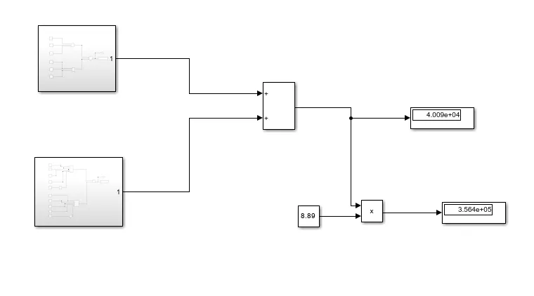
In this model two subsystems are used as one for rolling resistance force and another for airdrag force all calculations done through the blocks using formulas same as in problem above and values are also the same.
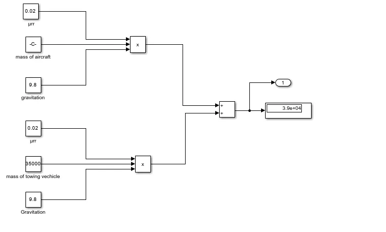
this block above shows inside the rr force subblock where the both aircraft and towings forces are calculated.
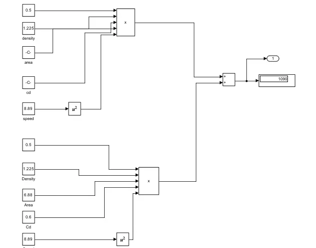
in the above blockset the airdrag forces of the both vehicles are computed and displayed and hence the total power and force are calculated using simulink model.
7. A. Design an electric powertrain with type of motor, it’s power rating, and energy requirement to fulfill aircraft towing application in Simulink. Estimate the duty cycle range to control the aircraft speed from zero to highest. Make all required assumptions. Prepare a table of assumed parameters. Draw a block diagram of powertrain.
(Hint :DC7 Block)
ans:
the following parameters and values are for ref.
- Mass of the aircraft (m_aircraft) = 164,000 kg
- Height of the aircraft (h_aircraft) = 15.80 m
- Width of the aircraft (w_aircraft) = 43.90 m
- Drag coefficient of the aircraft (Cd_aircraft) = 0.0265
- Air density (ρ) = 1.225 kg/m⊃3;
For the towing vehicle:
- Mass of the towing vehicle (m_towing) = 35,000 kg
- Height of the towing vehicle (h_towing) = 2.0 m
- Width of the towing vehicle (w_towing) = 3.4 m
- Drag coefficient of the towing vehicle (Cd_towing) = 0.6
- Towing speed (v) = 8.89 m/s (converted from 32 kmph)
perform the calculations similar to the previous response:
Energy Required:
1. Power (P) calculated earlier = 356.41 kW
2. Time (t) assumed as 20 minutes, converted to hours = 0.33 hours
Using the formula: Energy = Power × Time
Energy = 356.41 kW × 0.33 hours
Energy = 117.6 kWh
So, the energy required for the specified power over 20 minutes is 117.6 kWh.
Duty Cycle Calculation:
1. Input Voltage (V) = 650 V
2. Input Current (I) = 600 A
Calculate Power Input:
Power Input = Input Voltage × Input Current
Power Input = 650 V × 600 A
Power Input = 390,000 W
Power Input = 390 kW
Now, calculate the duty cycle:
Duty Cycle = Power Output / Power Input
Duty Cycle = 356.41 kW / 390 kW
Duty Cycle ≈ 0.9141
To express the duty cycle as a percentage:
% Duty Cycle = Duty Cycle × 100
% Duty Cycle = 0.9141 × 100
% Duty Cycle ≈ 91.41%
So, the duty cycle required for towing the vehicle TBL280 is approximately 91.41%.`
the block diagram is given as in block and image:
+------------------------+
| |
| Electric Motor |
| |
+------------+-----------+
|
| Control
|
+------------v-----------+
| |
| Duty Cycle Generator |
| |
+------------+-----------+
|
| Power
|
+------------v-----------+
| |
| Aircraft Load |
| |
+------------------------+
A block diagram of an aircraft towing powertrain typically consists of key components such as an electric motor, motor controller, duty cycle generator, aircraft load, and optional feedback sensors, control system, battery or power source, and mechanical transmission. The electric motor, controlled by the motor controller and duty cycle generator, provides the necessary mechanical power to move the aircraft load. Feedback sensors and a control system may be included for precise control, while a power source supplies the electrical energy required. The output force applied to the aircraft load and the resulting mechanical power are central to the powertrain's operation, with electrical connections facilitating communication between components. The design of such systems considers the specific aircraft, towing requirements, and operational conditions for efficient and safe towing operations.
the simulink model of dc drive is shown :
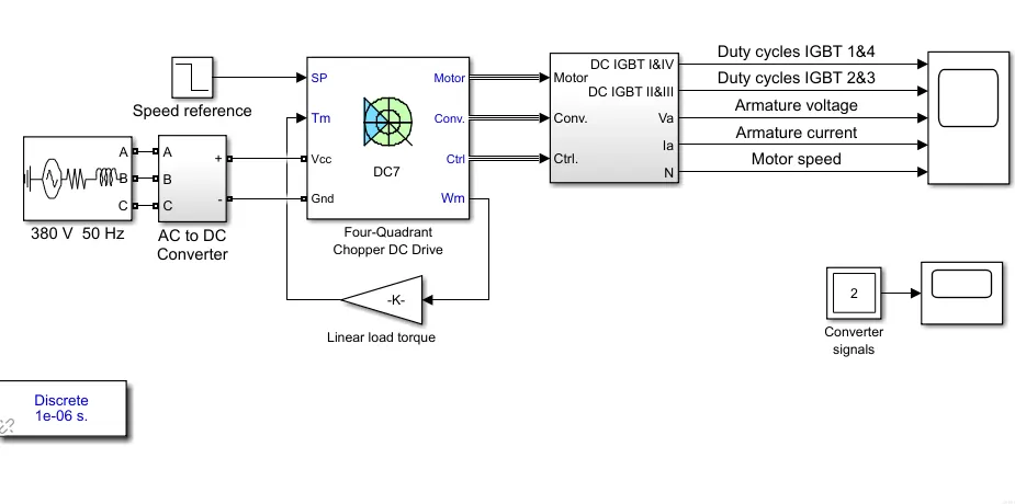
the scope results showing the required parameters are also plotted here:
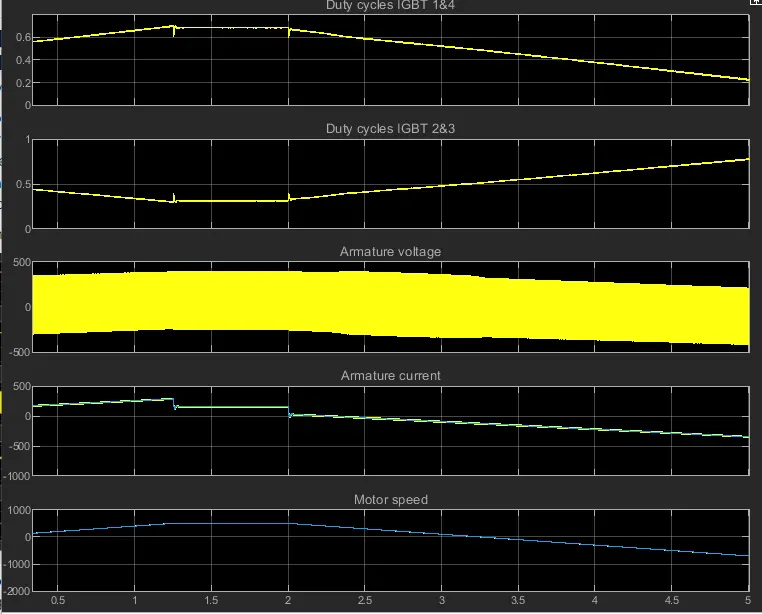
In the above result plot we have observed the plots of Duty cycles, Armature volte, armature current and Motoor speed. We can observe that when the motor reaches it highest voltage and current, the speed of the motor maintained constant. And till then the speed is increasing.
B. Also, Design the parameters in excel sheet.
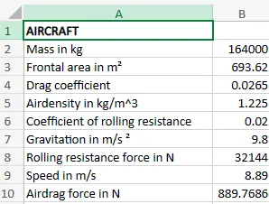
the link to the excel is here:
https://1drv.ms/x/s!AghcWEY04dtvhVs9Zc-NIaONB4B8?e=1IBTpd&nav=MTVfezAwMDAwMDAwLTAwMDEtMDAwMC0wMDAwLTAwMDAwMDAwMDAwMH0