Project-1: Powertrain for aircraft in runways
1.Search and list out the total weight of various types of aircrafts.
MTOW-Maximum Take off weight
The maximum taxi weight (MTW) (also known as the Maximum Ramp Weight (MRW) is the maximum weight authorized for maneuvering (taxiing or towing) an aircraft on the ground as limited by aircraft strength and airworthiness requirements. It includes the weight of taxi and run-up fuel for the engines and the APU (Auxillary Power Unit).
It is greater than the maximum takeoff weight due to the fuel that will be burned during the taxi and runup operations.
The difference between the maximum taxi/ramp weight and the maximum take-off weight (maximum taxi fuel allowance) depends on the size of the aircraft, the number of engines, APU operation, and engines/APU fuel consumption, and is typically assumed for 10 to 15 minutes allowance of taxi and run-up operations.
The maximum takeoff weight (also known as the maximum brake-release weight) is the maximum weight authorised at brake release for takeoff, or at the start of the takeoff roll.
The maximum takeoff weight is always less than the maximum taxi/ramp weight to allow for fuel burned during taxi by the engines and the APU.
In operation, the maximum weight for takeoff may be limited to values less than the maximum takeoff weight due to aircraft performance, environmental conditions, airfield characteristics (takeoff field length, altitude), maximum tire speed and brake energy, obstacle clearances, and/or en route and landing weight requirements.
MLW-Maximum Landing Weight-
The maximum weight authorised for normal landing of an aircraft.The MLW must not exceed the MTOW.
The operation landing weight may be limited to a weight lower than the Maximum Landing Weight by the most restrictive of the following requirements:
- Aircraft performance requirements for a given altitude and temperature:landing field length requirements,approach and landing climb requirements
- Noise requirements
If the flight has been of short duration, fuel may have to be jettisoned to reduce the landing weight.
Overweight landings require a structural inspection or evaluation of the touch-down loads before the next aircraft operation.

2. Is there any difference between ground speed and air speed?
The reference point is fixed to the ground but it could just as easily be fixed to the aircraft itself.
Relationships of wind speed to ground speed and airspeed
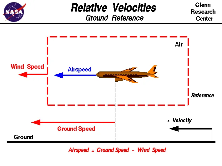 |
i m taking this figure from google image to demonstrate
WIND SPEED-
For a reference point picked on the ground, the air moves relative to the reference point at the wind speed. Notice that the wind speed is a vector quantity and has both a magnitude and a direction. Direction is important.
A 20 mph wind from the west is different from a 20 mph wind from the east. The wind has components in all three primary directions (north-south, east-west, and up-down). In this figure, we are considering only velocities along the aircraft's flight path. A positive velocity is defined to be in the direction of the aircraft's motion. We are neglecting cross wind which occur perpendicular to the flight path but parallel to the ground, and updrafts and downdrafts which occur perpendicular to the ground.
GROUND SPEED-
For a reference point picked on the ground, the aircraft moves relative to the reference point at the ground speed. Ground speed is also avector quantity so a comparison of the ground speed to the wind speed must be done according to rules for vector comparision.
Ground speed is the horizontal speed of an aircraft relative to the ground. An aircraft heading vertically would have a ground speed of zero. Information displayed to passengers through the entertainment system often gives the aircraft ground speed rather than airspeed.
Ground speed can be determined by the vector sumof the aircraft's true airspeed and the current wind speed and direction; a headwind subtracts from the ground speed, while a tailwind adds to it. Winds at other angles to the heading will have components of either headwind or tailwind as well as a crosswind component.
AIRSPEED-
The important quantity in the generation of lift is the relative velocity between the object and the air, which is called the airspeed. Airspeed cannot be directly measured from a ground position, but must be computed from the ground speed and the wind speed. Airspeed is the vector diff between the ground speed and the wind speed.
Airspeed = Ground Speed - Wind Speed
On a perfectly still day, the airspeed is equal to the ground speed. But if the wind is blowing in the same direction that the aircraft is moving, the airspeed will be less than the ground speed.
Taking an example-
Suppose we had an airplane that could take off on a windless day at 100 mph (liftoff airspeed is 100 mph). We are at an airport with an east-west runway that is 1 mile long. The wind is blowing 30 mph towards the west and the airplane takes off going east. The wind is blowing towards the aircraft which we call a headwind. Since we have defined a positive velocity to be in the direction of the aircraft's motion, a headwind is a negative velocity. While the plane is sitting still on the runway, it has a ground speed of 0 and an airspeed of 30 mph:
Airspeed = Ground Speed (0) - Wind Speed (-30) = 30 mph
The airplane starts its take off roll and has a constant acceleration a. From Newton's second law of motion, the ground speed V at any time t is:
V = a * t
and the distance d down the runway at any time is:
d = 1/2 * a * t^2
For a fixed length runway, this specifies the time to be used in the velocity equation. Let's assume that at 5000 feet down the runway, the velocity is 80 mph. Then the airspeed is given by
Airspeed = Ground Speed (80) - Wind Speed (-30) = 110 mph
and the airplane begins to fly.
Now another pilot, with exactly the same airplane decides to take off to the west. The wind is now in the same direction as the motion and this is called a tailwind. The sign on the wind speed is now positive, not negative as with the headwind. The acceleration along the ground is the same, so at 5000 feet down the runway, the ground speed is again 80 mph. The airspeed is then given by:
Airspeed = Ground Speed (80) - Wind Speed (30) = 50 mph
This airplane doesn't have enough airspeed to fly. It runs off the end of the runway
BEST example
A kite usually has no ground speed because a kite is held on the end of a string But the kite still has an airspeed that is equal to the wind speed. You can fly a kite only with the wind at your back.
3. Why is it not recommended to use aircraft engine power to move it on the ground at Airport?
The risks which may arise from engine ground running relate to the potential for loss of control of the aircraft by those persons occupying the pilot seats in the flight deck. Unwanted consequences from such static running are mainly related to those arising from the unintended movement of the aircraft during engine running - effectively a loss of control - especially during high power engine running. Damage can occur to the aircraft itself, other aircraft nearby or to airside structures. In addition, there is a risk of injury to ground support personnel who may be in relatively close proximity to the aircraft.
4. How an aircraft is pushed to runway when its ready to take off?
In aviation,pushbacck is an airport procedure during which an aircraftis pushed backwards away from an airport gate by external power. Pushbacks are carried out by special, low-profile vehicles called pushback tractors or tugs.
Although many aircraft are capable of moving themselves backwards on the ground using reverese thrust (a procedure referred to as a powerback), the resulting jetblast or propwash might cause damage to the terminal building or equipment. Engines close to the ground may also blow sand and debris forward and then suck them into the engine, causing damage to the engine. A pushback is therefore the preferred method to move the aircraftt away from the gate.
Pushbacks at busy aerodromes are usually subject to ground control clearance to facilitate ground movement on taxiways. Once clearance is obtained, the pilot will communicate with the tractor driver (or a ground handler walking alongside the aircraft in some cases) to start the pushback. To communicate, a headset may be connected near the nose gear.
Since the pilots cannot see what is behind the aircraft, steering is done by the pushback tractor driver and not by the pilots. Depending on the aircraft type and airline procedure, a bypass pinmay be temporarily installed into the nose gear to disconnect it from the aircraft's normal steering mechanism.
Once the pushback is completed, the towbar is disconnected, and any bypass pin removed. The ground handler will show the bypass pin to the pilots to make it clear that it has been removed. The pushback is then complete, and the aircraft can taxi forward under its own power
5.Learn about take off power, tyre design, rolling resistance, tyre pressure, brake forces when landing
Take off power-The amount of power that an engine is allowed to produce for a limited period of time for takeoff. The use of takeoff power is usually limited to 5 min for reciprocating engines and up to 2½ min for gas turbine engines. This may not always be the case. Specifically, with respect to reciprocating engines, it is the brake horsepower developed under standard, sea-level conditions and under the maximum conditions of the crankshaft rotational speed and the engine manifold pressure approved for the normal take off It is limited in continuous use to the period of time shown in the approved engine specifications. With respect to gas turbine engines, it is the thrust developed under static conditions at a specified altitude and atmospheric conditions of the rotor shaft rotational speed and gas temperature approved for the normal takeoff.
Tyre design-
When it comes to safety, tyres are one of the most important components of aircraft. They help to absorb the shock of landing and provide cushioning. It also provides the necessary traction for braking and stopping of an aircraft.
An aircraft tyre is designed to withstand extremely heavy loads while landing, take off, taxing, and parking. The number of wheels required for aircraft increases with the weight of the aircraft, as the weight of the aeroplane needs to be distributed more evenly
A radial tyre has the fibre strands of the ply fabric oriented with and at 90° to the direction of rotation and the tyre sidewall. This restricts flexibility bidirectionally and the flexibility of the sidewall while it strengthens the tyre to carry heavy loads.Most radial tyres are resistant to penetrations and cuts, especially in the tread area due to their unique construction process. In fact, only a small portion of the radial tyre will be affected in case of any damage.
A bias-ply tyre has the fabric bias oriented with and across the direction of rotation and the sidewall. Since fabric can stretch on the bias, the tyre is flexible and can absorb loads. Tyre strength is obtained by adding plies. Bias-ply tires are cut resistant in the sidewall area. However, if there is any cut in the tread area, it can affect only a small portion of tyre.
Radial tyres are a newer design. Traditional aircraft were using Cross Ply tyre. The choice of tyre in aircraft only depends on manufacturer type certificate data sheet. Radial tyres are in demand because of their long term value, although they are more expensive than bias-ply tyres.
Rolling resistance-
Rolling resistance is the combination of forces that work against the forward motion of your vehicle. The weight of the vehicle, gravity and inertia, the amount of friction between the tires and the road surface, and air drag all play a part. When you coast in your car or on a bike, rolling resistance is what slows you down. The more rolling resistance, the more power it takes to propel a vehicle. Between 3 and 11 percent of the fuel used in passenger vehicles goes to overcoming this force, so reducing it means saving on fuel.
Since tires contribute to between 15 and 25 percent of a vehicle’s overall rolling resistance — depending on how fast you’re going, vehicle type and road surface — they are a significant factor
Tyre pressure-
Aircraft tires are usually inflated with nitrogen to minimize expansion and contraction from extreme changes in ambient temperature and pressure experienced during flight. Dry nitrogen expands at the same rate as other dry atmospheric gases but common compressed air sources may contain moisture, which increases the expansion rate with temperature.
Tests of airliner aircraft tires have shown that they are able to sustain pressures of maximum 800 psi or 55 bar before bursting. During the tests the tires have to be filled with water, to prevent the test room being blown apart by the energy that would be released by a gas when the tire bursts.
The main landing gear on the Concorde was typically inflated to 232 psi or 16.0 bar whilst its tail bumper gear tires were as high as 294 psi (20.3 bar).
Brake forces when landing-
Aircraft brakes stop a moving aircraft by converting its kinetic energy to heat energy by means of friction between rotating and stationary discs located in brake assemblies in the wheels In general, when the wheels touch the ground, a set of spoilers raise up quickly, which kills the lift provided by the wings.
While the spoilers provide some drag, their primary purpose is to stop the plane from actually flying, putting all of the weight on the landing gear and in turn making the brakes that much more effective. ircraft have highly-engineered, multi-disc brakes made of a carbon-steel material Manufacturers include Honeywell and Goodrich, part of Collins Aerospace. In general, the brakes are composed of discs that rotate with the wheel and separate discs that are fixed.
Auto brakes-Wheel brakes are usually selected to engage automatically after landing. These are called auto brakes
To push or pull an aircraft by a towing vehicle, 3 type of forces will act on that vehicle. Those are -
Part B:
6. A. With necessary assumptions, calculate the force and power required to push / pull an aircraft by a towing vehicle.
let us assumed
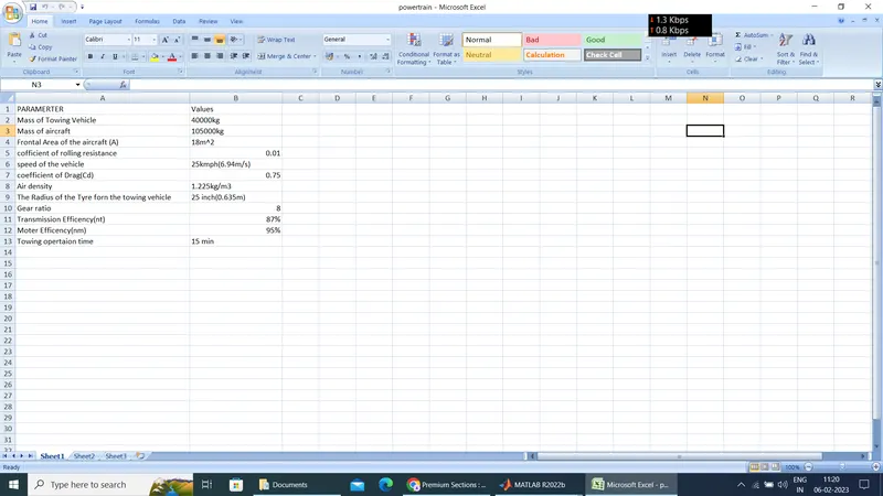
Mass of Towing Vehicle= 40,000kg
Mass of aircraft = 105,000kg
Total mass (m)= 40,000+105,000 =145000
Frontal Area of the aircraft (A) =18 m²
Coefficient of rolling resistance (Urr)=0.01
Speed of the vehicle (2)=25Kmph
converting it into m/sec
u=25*(1000/3600)=6.94m/sec
Drag coefficient (Cd) =0.75
Air density (P)=1.205Kg/m³
Calculating Rolling resistance Force (Frr) =Urr*m*g
=0.01*145.000*9.8
= 14210N
Calculating Aerodynamic Drag Force (Fd)=0.5*p* Cd*A* v^2
=0.5 *1.205 * 0.75*18* (6.94)2
=8.133*48.16N
= 391.68N
Therefore the total Force required to push/pull the aircrcraft by the towing vehicle (F) Frr+Fd
=14210N+391.68N
=14601.68 N
Calculating the power (p) =Force*Velocity
=14601.68*6.94
=145140.69
=145kw
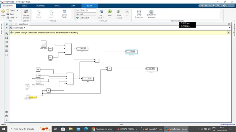
B. Develop the model for the calculated force and power using Simulink.
Blocks Used:
1) Constant-
2) Sum
3) Product
4)Square
5)Display
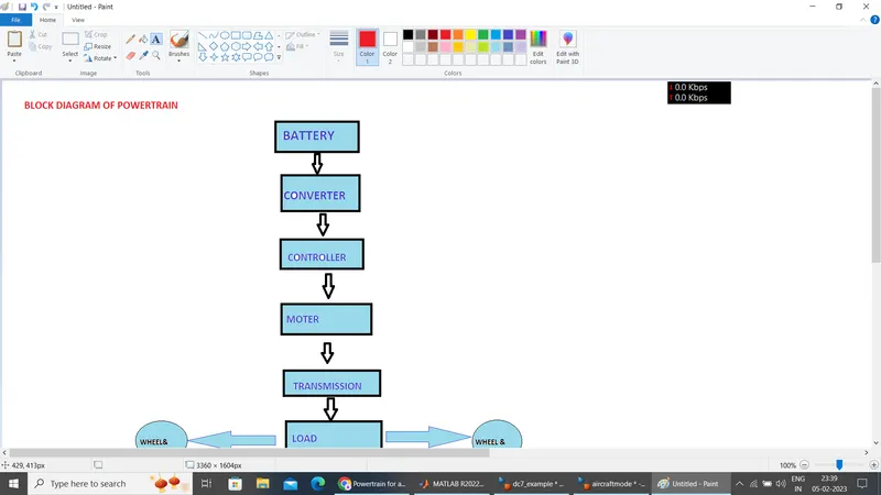
7. A. Design an electric powertrain with type of motor, it’s power rating, and energy requirement to fulfill aircraft towing application in Simulink. Estimate the duty cycle range to control the aircraft speed from zero to highest. Make all required assumptions. Prepare a table of assumed parameters. Draw a block diagram of powertrain.
BLOCK DIAGRAM-
Based on the calculations done in 6(A).
Taking the prevoius example power value 145 kW for this problem
Power =145 kW
Force required to push/pull the aircraft = 14601.68 N
=14.60kN
Let us assume,
The Radius of the Tyre for the Tug - 25inches =0.635m
Gear ratio=8
Transmission Effeciency (nt) =87%
Motor Efficiency (nm)=95%
then,
Torque required for the wheels (Tw)=Total Force *Radius in meters
=14.60 *0.635
=9.2720KNm
Motor Torque=Wheel torque/(Gear ratio*'nt)
=9.2720/(8*0.87)
=1.3321KNm
For nm =95%. The required motor Torque (Tm)= 1.3321/0.95 =1.402 kNm
Similarly. The total power required by the motor considering all the efficiencies (Pt) = 145/(0.87*0.95)=175.4Kw
Let us assume the towing operation was done for a 15 minutes (0.25Hrs) duration.
Then, Total Energy consumed = 175.4* 0.25=43.85KWh
If we consider the battery capacity=220 kw is used by the towing vehicle then.
Duty Cycle (d)= (Required Power)/ (Rated power)= 175.4/220 =0.797
Therefore the controller will be able to provide a duty cycle ranging from 0 to 79% in order to control the towing speed.
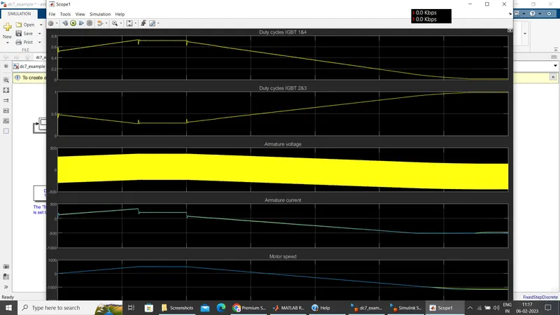
using dc7 block-
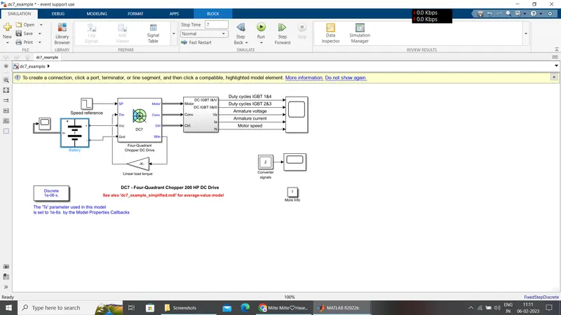
Assume or taking ref of MOTER Specification for 150kw
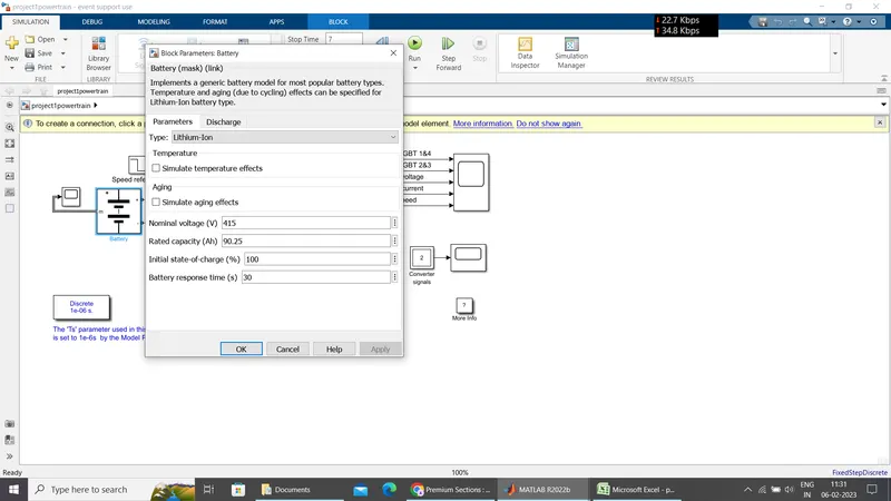
Electric moter 6P 150 kW 3ph 415V 315l FT
v=450
i=150kw/450
=361A
put it on the battery capcity
nominal voltage=415
ah=361*0.25=90.25ah
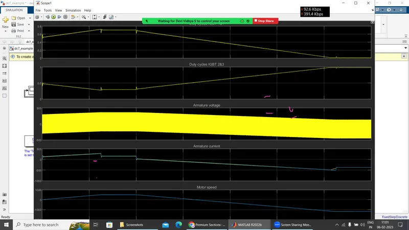
without changing moter torque
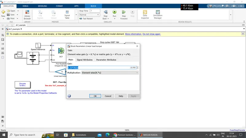
changing linear torque value 1.3321(Moter torque)
EXCEL sheets