Project-1: Powertrain for aircraft in runways
Project-1: Powertrain for Aircraft in Runways
Part A:-
Objective:-
- To search and list out the total weight of various types of aircrafts.
- To distinguish between Air speed & Ground Speed.
- We have to describe why is it not recommended to use aircraft engine power to move it on the ground at Airport.
- To describe that how an aircraft is pushed to runway when its ready to take off.
- To learn about take off power, tyre design, rolling resistance, tyre pressure, brake forces when landing.
Explanation:-
#Study 1:- Search and list out the total weight of various types of aircrafts.
Ans:- Aircraft Gross Weight:-
- Actually, aircraft gross weight is defined as the total weight at any moment during flight or ground operation.
- The aircraft gross weight decreases due to fuel or oil consumption during flight.
- In some case gross weight (aircraft) may vary due to drop in payload or inflight refueling,where as on the other hand when the brakes are released the gross weight will be equal to take off weight.
- As we know, the weight is the force generated vy the gravitational force of earth which is calculated by using the formula W=m*g, where W is the weight of object, m is the mass of object & g is the acceleration due to gravity which is equal to 9.8 m/s.
- if we want to calculate the weight of an aircraft then there are different parts having different masses such as fuel, engine, body, tail,wings etc.
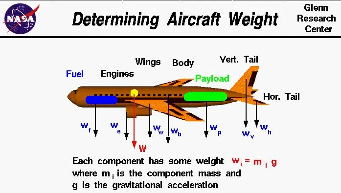
- Here we can see that, there are 8 different parts having different wights.
- so in order to calculate the total weight of an Aircraft, we have to add these weights.
- so total wight (W) = Wf + We + Ww + Wb + Wp + Wv + Wh
Types of Aircraft weights are:-
(a) Manufacturer's Empty Weight (MEW):-
- It includes the weight of entire flight with it's all interior working parts such as Gear, rubber, wings, main engine, APU, Power plants etc.
- But it excludes baggage, passenger& fuels.
(b) Zero Fuel Weight (ZFW):-
- If we add the payload weight with the empty plane weight, then we will get the Zero fuel weight (ZFW).
- payload includes passenger's weight, weight of luggages & cargo weight.
- Passenger's weight is the standard weights used defined by ICAO.
(c) Maximum Take-off weight (MTOW):-
- Actually,Fuel burn during taxi operation to the departure runway reduces the gross weight. At the holding point, we have the Actual Take-off Weight (ATOW) which is used for take-off performance calculation.
- Aircraft gross weight reduces due to to fuel & oil consumption during flight.
- it also varry due to inflight refueling & payload dropping.
(d) Regulated Take-off Weight(RTOW):-
- Depending on different factors (flap setting,altitude,lenght of runway),RTOW varies for each take off,but can never be high for MTOW.
(e) Maximum Landing Weight (MLW):-
- After subtracting the weight varriation due to oil consumption,inflight refueling & payload drop then the current weight with which an aircraft is about to land is called as Maximum landing weight.
- It is the maximum weight at which an aircraft is permitted to land.
(f) Maximum Ramp Weight(MRW):-
- It is the maximum weight used for manuevering (towing) aircraft on the ground.
|
Aircraft |
Empty Weight (kg) |
Max. Fuel Weight (kg) |
Max.Cargo Weight (kg) |
Max. Gross Take-off weight (kg) |
|
2,85,000 |
3,00,000 |
190,000 |
6,40,000 |
|
|
2,77,000 |
2,54,000 |
84,000 |
5,75,000 |
|
|
2,20,000 |
1,94,000 |
1,34,000 |
4,47,700 |
|
|
1,68,000 |
1,75,000 |
54,000 |
3,72,000 |
|
|
1,35,500 |
1,01,500 |
57,300 |
2,54,000 |
|
|
24,500 |
21,900 |
3,000 |
45,200 |
|
|
17,800 |
5,300 |
8,500 |
28,000 |
|
|
3,200 |
1,450 |
1,900 |
5,400 |
|
|
1,450 |
155 |
560 |
2,000 |
|
|
1,000 |
220 |
430 |
1,630 |
(**) https://pilotteacher.com/how-much-do-airplanes-weigh-with-20-examples/
#Study2:- Is there any difference between ground speed and air speed?
Ans:-
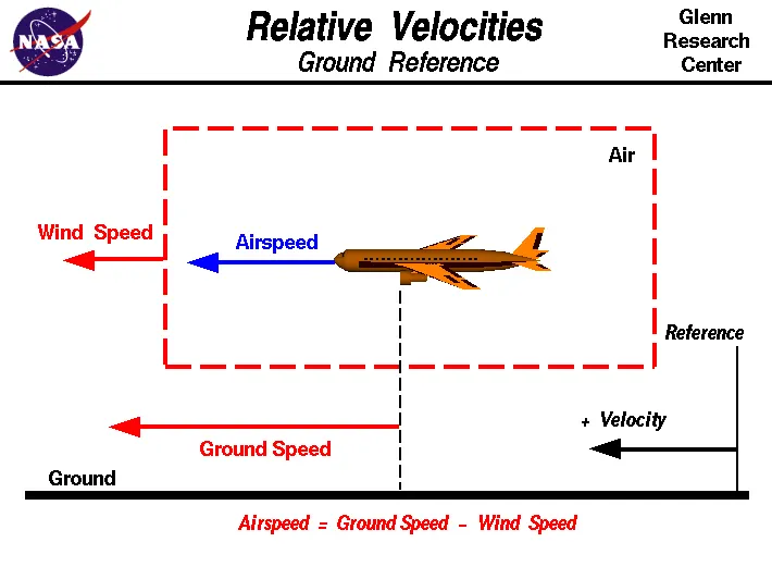
- From the above figure, we can see that there are 3 different speeds are associates flying of an Aircraft.
- such as Air speed, Wind speed & Ground speed.
- Wind Speed:- Wind speed is the speed which either push the aircraft when blows in opposite direction to the direction of movement of the aircraft & on the other hand wind speed helps in increasesing the speed of aircraft when it blows in the same direction with the aircraft.
- so we can simply say that wind speed is a vector quantity means it has both magnitude & direction.
- direction of wind speed is very very important because as we discussed above if the direction of wind changes then there is a effect on the fuel & oil consumption.
- wind can blow in all directions like north-south, east-west & up-down.
- Gound Speed:- For a reference point picked on the ground, the aircraft moves relative to the reference point at the ground speed. Ground speed is also a vector quantity so a comparison of the ground speed to the wind speed must be done according to rules for vector comparisons.
- Air Speed:- Air speed is the relative speed between ground speed & wind speed.
- Air speed is the major quantity for lifting an aircraft.
- Air speed cann't determine directly, so we can determine by using the above formula.
- From the above figure, we can simply say that, the air speed is the vector difference between Ground speed & wind speed.
Air Speed = Ground Speed - Wind Speed
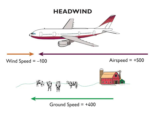
- So we can simply say that, Ground speed is different than Air speed.
- Ground speed is how fast an airplane's shadow would move across the land. If there's a strong wind pushing an aircraft, that's reflected in the ground speed.
- Airspeed, in contrast, is how fast an airplane is really flying strictly under its own power, which is calculated by subtracting the wind speed from the ground speed.
- If the wind speed is 0 then air speed will be equal with ground speed.
#Study3:- Why is it not recommended to use aircraft engine power to move it on the ground at Airport?
Ans:- Actually, most of aircrafts can move itshelf in reverse manner by using the reverse thrust technology.But in most of the practical it is not possible because when airplanes start using reverse thrust it will consume lot of fuels as well as causes lot of noise and also hazardous for the people working near by.
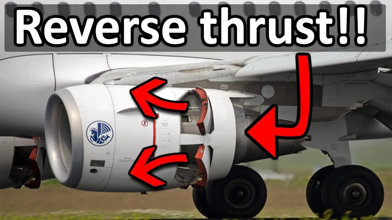
- The another reason for not using the reverse thrust is the plane blast which will cause damage to the big buildings & it's equipement.
- Since the engine is also close to the ground it will blow off the sand and debreis forward and sucks it to the engine and causes damage to it.
- Usage of low power mounted engines have a risk of impurities on the ground may enter inside the engine.
- So in order to overcome these problems, we are recommonded to use a towing vehicle which tows the aircraft in reverse direction to a safe place from where it will safely take-off further.
#Study4:- How an aircraft is pushed to runway when its ready to take off?
Ans:- There are two methods are used to push an aircraft into runway when it is ready to take-off. such as:-
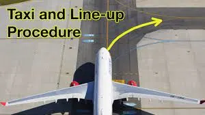
- Taxiing
- Towing
(A) Taxiing:-
- It is defined as the movement of an aircraft to the ground by it's own power.
- An aircraft moves through wheels on ground the term also used for the air-craft that has skies or floating equipments.
- An aeroplane uses taxiways to move from one place to another place on the same airport.
(B) Towing:-
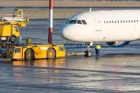
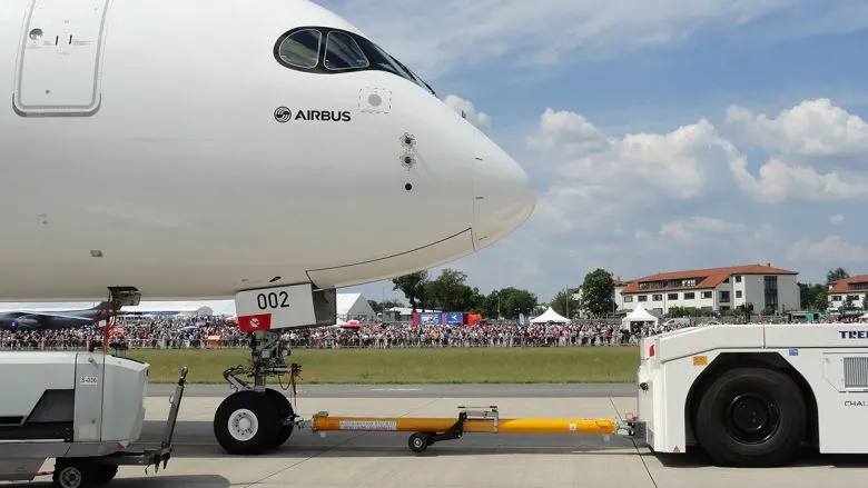
- In case of towing or pushback, an aircraft is moved by a tug.
- Movement of large aircraft about the airport, flight line & hangar is usually accomplished by towing with a tow tractor called as tug.
- A pushback truch lifts the front wheel of the aircraft, their role in most airports is to move the aircraft away from the parking spot on the taxiways.
- Here the truck is removed & when all platform staffs are out of the way, then the engines are started one after another.
- Towing aircraft can be a hazardous operation, causing damage to aircraft & injury to personnel, if done carelessly.
- In the case of small aircraft, some moving parts is accomplished by hand pushing into the correct area of aircraft.
#Study5:- Learn about take off power, tyre design, rolling resistance, tyre pressure, brake forces when landing.
Ans:- (A) Take-off Power:-
- Take-off is the starting phase for an aircraft where an aircraft leaves the ground & becomes airborne.
- When an aircraft travels vertically, it is called as lift-off.
- For an aircraft that take-off horizontally,then it is compolsory to move in the ground 1st in the same direction of take-off then it can fly or it can take-off easily.
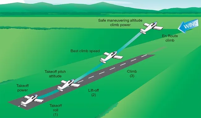
- For light aircraft,usually full power is used during take-off.
- After towing the aircraft into the runways, it is very very important that the aircraft should aligned with the intented take-off direction.
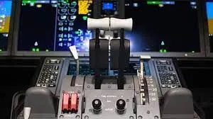
- after releasing the brake padels, the throttles are smoothly provide the take-off power.
- Takeoff power can be determined by using the force equillibrium along with the runways as:-
- T is the Thrust developed by Tug during the pushing of aircraft along the runways.
- D is the areodynamic drag co-efficient which resists the motion of an aircraft
- F is the rolling resistance friction force developed between the tyre & the ground.
so, during the take-off, the imbalance of these forces developes an acceleration along the runway.
dV/dt = (T-D-F)/m
Where,
- dV/dt is the acceleration along the runway
- m is the mass of the vehicle
(B) Tyre Design:-
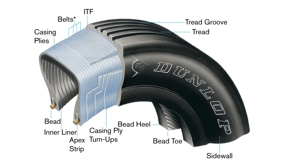
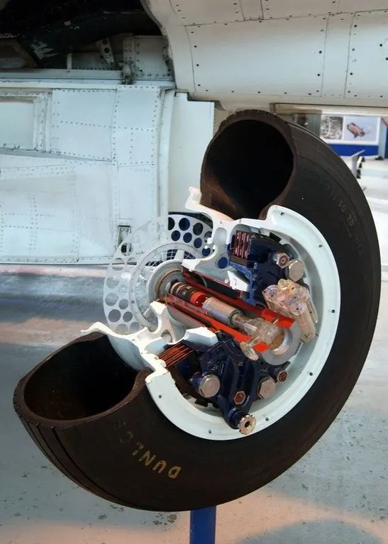
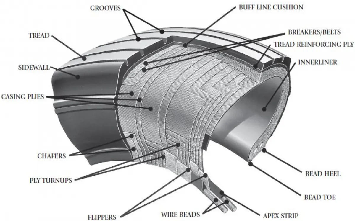
(C) Rolling Resistance:-
- Rolling resistance force is the resisting force which opposes the motion of a vehicle or any object rolling on a surface or ground.
- sometimes it is called as rolling drag or rolling friction.
- It is mainly caused by non-elastic effects.
- some researchers have included this term in rolling resistance, some suggest that this dissipation term should be treated separately from rolling resistance because it is due to the applied torque to the wheel and the resultant slip between the wheel and ground, which is called slip loss or slip resistance.
- Rolling resistance force can be calculated by using the following formula as:-
Frr= Crr*m*g
Where,
- Frr is the rolling resistance force.
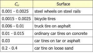
- Crr is the co-efficient of rolling resistance
- m is the mass of vehicle
- g is the acceleration due to gravity
so, co-efficient of rolling resistance may varry for different surface as:-
(D) Tyre Pressure:-
- Airplane tires are designed to withstand a wide range of operating conditions, including carrying very high loads and operating at very high speeds.
- It is common for a jet airplane tire to carry loads as heavy as 60,000 pounds while operating at ground speeds up to 235 miles per hour.
- Generally,a aircraft tyre can handle upto 38 ton load.
- It can meet the grounds 500 times before needing a re-tread, a refresh it can take on seven times in it's life.
(E) Brake force when landing:-
- In aircraft types,the brake units are powered by the hydraulics system.
- An electrical signal is sent from the flight deck to hydraulic actuators nera the main landing gear.
- Here,hydraulic fluid at 3,000 pound per square inch is used to force the brake unit against the wheel, thus slowing it down.
Part:-B
6. A. With necessary assumptions, calculate the force and power required to push / pull an aircraft by a towing vehicle.
Ans:- As we know, an aircraft is pushed or pulled by a tow machine called as Tug. so in order to calculate the required force to puch or pull an aircraft by a tug, we have to determine the following parameters, such as:-
- Rolling resistance Force for both aircraft & Tug
- Aerodynamic Drag force for bith aircraft & Tug.
(A) Rolling Resistance force:-
- It is a type of opposing force which is created between the two surfaces such as road & tyre of the vehicle.
- When a vehicle starts to run on a road then this rolling resistance force opposes the vehicle.
- we can calculate this force by using the following formula such as:-
Frr =  *m*g -------------------------(1)
Where,
- Frr is the Rolling resistance force.
- is the co-efficient of rolling resistance force.
- m is the total mass of the vehicle.
- g is the acceleration due to gravity.
(B) Aerodynamic Drag Force:-
- It is a type of resisting force which opposesthe motion of a body when it rolls on a surface.
- there are several factors in the air which opposes the motion of a running vehicle.
- we can determine the aerodynamic drag force by using the following formula.

Where,
- Fd is the aerodynamic drag force
 is the air density
- v is the velocity of the vehicle
- Cd is the drag co-efficient
- A is the frontal area of the vehicle
So, in order to calculate the force & power required to push & pull an aircraft by a Tug then we have to take some assumptions as given as follows:-
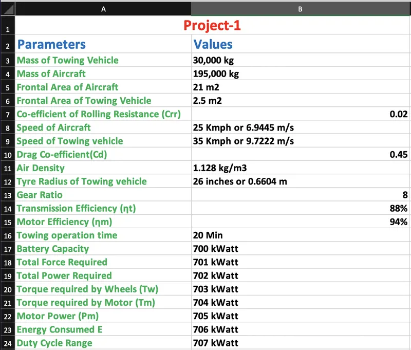
- Mass of Towing Vehicle= 30,000 kg
- Mass of aircraft = 195,000 kg
- Total mass (m)= 30,000+195,000 =225,000 kg
- Frontal Area of the aircraft (A1) =21 m2
- Speed of the aircraft (V1) =25 Kmph
- Frontal Area of Tug (A2) = 2.5 m2
- converting it into m/sec, (V1) = 25*(1000/3600)=6.9445 m/sec
- Speed of Tug (V2) = 35 Kmph
- converting it into m/sec, (V2) = 35*1000/3600 = 9.7222 m/s
- Drag coefficient (Cd) =0.45
- Air density ( ) =1.128 Kg/m3
- Co-efficient of rolling resistance () = 0.02
- Acceleration due to gravity (g) = 9.8 m/s^2
so, Rolling Resistance Force (Frr) = *m*g
= 0.02*225000*9.8
= 44,100 N
& Aerodynamic Drag Force (Fd1) = 0.5*ρ*A1*Cd*V^2
= 0.5*1.128*21*0.45*(6.9445)^2
= 257.0353 N
So Aerodynamic Drag Force (Fd2) = 0.5*ρ*A2*Cd*V^2
= 0.5*1.128*2.5*0.45*(9.7222)^2
= 59.9737 N
So, Total Force Required By Tug (F) = Frr + Fd1 + Fd2
= 44100 + 257.0353 + 59.9737
= 44,417.009 N ≈ 44,417 N
= 44.417 kN
So, Power required by the Tug (P) = Force * Velocity
= 44,417 * 9.7222
= 431,830.957 Watt ≈ 431,831 Watt
= 431.831 kW
∴ So we can say that, A Tow machine (Tug) requires 44.417 kN of force & 431.831 kW of power to push or pull an aircraft.
7. A. Design an electric powertrain with type of motor, it’s power rating, and energy requirement to fulfill aircraft towing application in Simulink. Estimate the duty cycle range to control the aircraft speed from zero to highest. Make all required assumptions. Prepare a table of assumed parameters. Draw a block diagram of powertrain.
(Hint :DC7 Block)
Ans:- Block Diagram of Powertrain:-
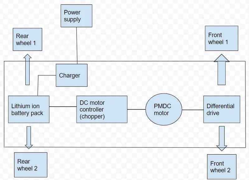
- The above block diagram represents the Powertrain blockset of towing vehicle which are used to push or pull an aircraft.
- From the diagram, we can see that there are 4 wheels (2 Front wheels & 2 Rear wheels).
- The battery pack is Lithium ion battery pack which are used to provide sufficient electrical power to different parts such as Motor, Controller,auxillary battery etc.
- Power supply is connected with the lithium ion battery pack through charger.
- then after getting charged, the battery pack will provide power to the controller which will control the operation of different parts inside the vehicle.
- Then There is a DC motor controller (Chopper) is connected with battery pack which will provide sufficient power to the Motor according to the rating of motor.
- Then a differential drive which carries the wheels is connected with the motor.
- then when motor starts to rotate then wheels also starts to rotate by the help of these transmission system (Differential drives).
As we have calculated in 6A as:-
- Total Force required by a Towing vehicle = 44.417 kN
- Total power required by a towing vehicle = 431.831 kW
Now, let's assume the following parameters as:-
- Radius of tyre of the Towing Vehicle = 26 inches = 66.04 cm = 0.6604 m
- Gear ratio = 8
- Transmission efficiency (ηt) = 88%
- Motor efficiency (ηm) = 94%
- time required fpr towing operation = 20 Minutes = 1/3 Hrs
- Battery capacity = 700 kW
Then,
- Torque required by the wheels (Tw) = Total Force*Radius of tyre of Tug
= 44.417*0.6604
= 29.333 kNm
- Motor Torque due to transmission efficiency (ηt) = Tw/(Gear Ratio*ηt)
= 29.333/(8*0.88)
= 4.1666 kNm
- for Motor efficiency (ηm=94%),
The required Motor torque (Tm) = 4.1666 / 0.94
= 4.4325 kNm
- Simillarily, the total Power required by the motor considering all efficiencies (Pm) = Total power/(ηt*ηm)
= 431.831/(0.88*0.94)
= 522.04 kWatt
- so, Energy consumed by the Towing operation (E) = Motor Power*Time duration for towing
= 522.04*(1/3)
= 174.013 kWh
- so,The duty cycle range to control the speed from 0 to max speed is given as = Required Power/ Battery capacity
= 522.04 / 700
= 0.74577 ≈ 0.75
- Therefore controller will provide range of duty cycle from 0% to 75% to control the towing speed.
Simulink Model:-
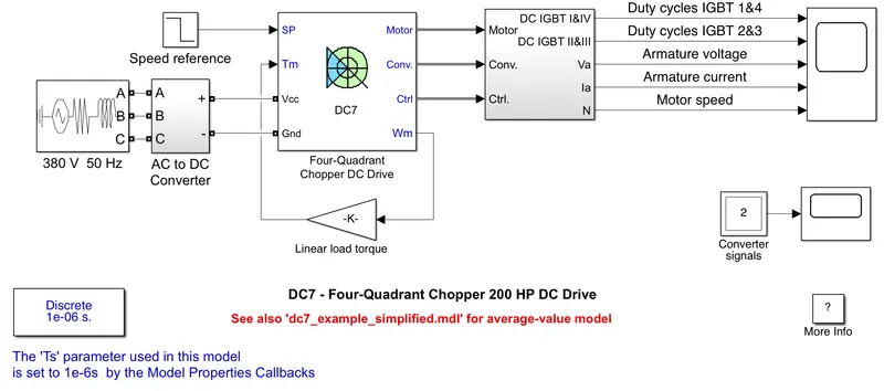
- The above model consists of 3-phase source of 380V 50 Hz rating, an AC to DC converter, a Four-quadrant Chopper DC drive, speed reference, gain block (Linear load torque),Selector subsystem, powergui & a scope.
- The 200 HP DC motor is separately excited with a constant 150 V DC field voltage source.
- The armature voltage is provided by an IGBT converter controlled by two PI regulators.
- The converter is fed by a 515 V DC bus obtained by rectification of a 380 V AC 50 Hz voltage source.
- In order to limit the DC bus voltage during dynamic braking mode, a braking chopper has been added between the diode rectifier and the DC7 block.
- The first regulator is a speed regulator, followed by a current regulator.
- The speed regulator outputs the armature current reference (in p.u.) used by the current controller in order to obtain the electromagnetic torque needed to reach the desired speed.
- The speed reference change rate follows acceleration and deceleration ramps in order to avoid sudden reference changes that could cause armature over-current and destabilize the system.
- The current regulator controls the armature current by computing the appropriate duty ratios of the 5 kHz pulses of the four IGBT devices (Pulse Width Modulation).
- For proper system behaviour, the instantaneous pulse values of IGBT devices 1 and 4 are opposite to those of IGBT devices 2 and 3.
- This generates the average armature voltage needed to obtain the desired armature current.
- In order to limit the amplitude of the current oscillations, a smoothing inductance is placed in series with the armature circuit.
- Before starting the simulation, set the initial bus voltage to 515 V via the GUI block ('Initial States Setting' button and 'Cbus' variable).
- Start the simulation. You can observe the motor armature voltage and current, the four IGBT pulses and the motor speed on the scope. The current and speed references are also shown.
- The motor is coupled to a linear load, which means that the mechanical torque of the load is proportional to the speed.
- The speed reference is set at 500 rpm at t = 0 s. Observe that the motor speed follows the reference ramp accurately (+400 rpm/s) and reaches steady state around t = 1.3 s.
- The armature current follows the current reference very well, with fast response time and small ripples. Notice that the current ripple frequency is 5 kHz.
- At t = 2 s, speed reference drops to -1184 rpm. The current reference decreases to reduce the electromagnetic torque and causes the motor to decelerate with the help of the load torque.
- At t = 2.2 s, the current reverses in order to produce a braking electromagnetic torque (dynamic braking mode). This causes the DC bus voltage to increase.
- At t = 3.25 s, the motor reaches 0 rpm and the load torque reverses and becomes negative. The negative current now produces an accelerating electromagnetic torque to allow the motor to follow the negative speed ramp (-400 rpm/s). At t = 6.3 s, the speed reaches -1184 rpm and stabilizes around its reference.
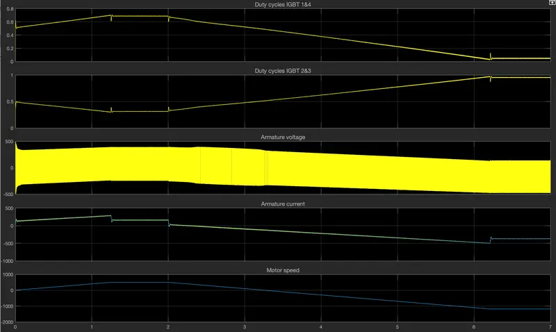
- From the scope result, we can see that when two IGBTs 1 & 4 are ON then armature fluctuated more with higher amplitude means high value of armature voltage.
- at that time, the armature cure current remains +ve which states that motor is in loaded conditions.
- Motor speed also increases & +ve.
- then when 2 & 3 IGBTs are ON, then armature voltages flactuate but with lower amplitude so we can say that voltage value becomes low.
- at that time, armature currents starts decreasing & becomes -ve which states that motor is in either charging or in regenerative conditions.
- Speed also become -ve which states that it motor charges it's direction of rotating & acts as generator.
B. Also, Design the parameters in excel sheet.
Ans:-