Study of Aircraft and Modelling of Powetrain in Runways
STUDY OF AIRCRAFT, PARAMETERS AND EVALUATE THE POWER REQUIRED TO TOW AN AIRPLANE :-
AIM :-
To study about aircraft and to evaluate the power required to tow the aircraft to the runways.
SYSTEM SPECIFICATIONS :-
- Manufacturer - DELL
- Model – Vostro 3478
- Operating System - Windows 10
- Processor - Intel(R) Core(TM) i5-8250U CPU @ 1.60GHz 1.80GHz
- RAM – 8 GB
OBJECTIVES :-
- Study about weight of different types of aircraft.
- Study of relation between air speed and ground speed.
- Study about engine power and coasting of aircraft in airport.
- To learn about aircraft parameters that are affecting the propulsion.
- To evaluate the power required to tow the aircraft from standby to the runways.
QUESTION & ANSWER :-
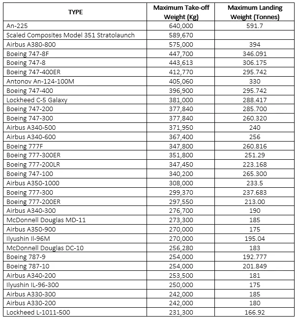
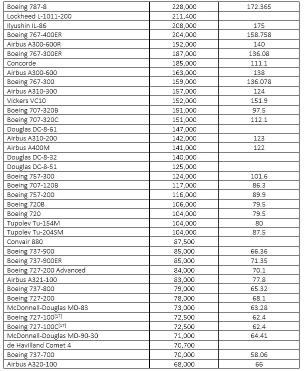
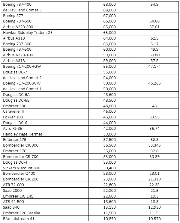
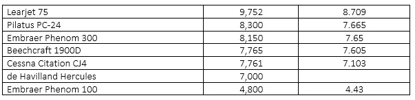
1) Search and list out the total weight of various types of aircrafts.
The aircrafts are being classified by two different weight categories namely,
- Maximum Take-off Weight
- Maximum Landing Weight
Maximum Take-off Weight :-
- The maximum take-off mass (MTOM), often referred to as maximum take-off weight (MTOW), of an aircraft is a value defined by the aircraft manufacturer.
- It is the maximum mass at which the aircraft is certified for take-off due to structural or other limits.
- MTOW is usually specified in units of kilograms or pounds.
Maximum Landing Weight :-
- The maximum landing weight is the maximum aircraft gross weight due to design or operational limitations at which an aircraft is permitted to land.
- The MLW is set in order to ensure safe landings; if an aircraft weighs too heavy during touchdown, it may suffer structural damage or even break apart upon landing.
Weight of various types of aircrafts :-
2) Is there any difference between the ground speed and the air speed ?
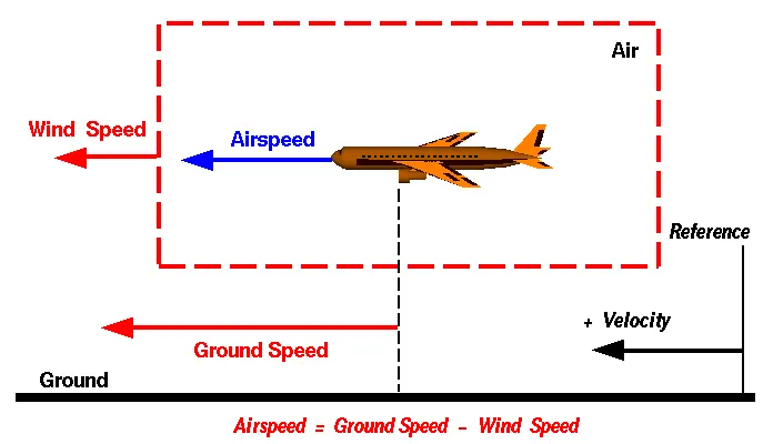
Wind Speed :-
- The rate at which the air is moving in a particular area (Kmph).
- It’s a vector quantity i.e., both magnitude and direction.
- We are considering only the velocities along with the aircraft direction.
- A reference point is considered, so that the air moves relative to the reference point at the wind speed.
Ground Speed :-
- Ground speed is the horizontal speed of an aircraft relative to the Earth’s surface.
- It is vital for accurate navigation to the destination that the pilot has an estimate of the ground speed that will be achieved during a flight.
- An aircraft diving vertically would have a ground speed of zero.
- A reference point is considered, so that the aircraft moves relative to the reference point at ground speed.
- It’s a vector quantity and the comparison of ground and wind speed to be followed by the rules of the vector comparisons.
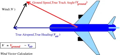
Air Speed :-
- The important quantity in the generation of lift is the relative velocity between the object and the air, which is called the
- Airspeed cannot be directly measured from a ground position, but must be computed from the ground speed and the wind speed.
- Airspeed is the vector difference between ground speed and wind speed,
Air Speed = Ground Speed – Wind Speed
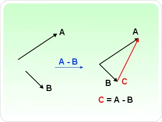
Relation between air speed and ground speed :-
- Airspeedis the vector difference between the ground speed and the wind speed.
- On a perfectly still day, the airspeedis equal to the ground speed. But if the wind is blowing in the same direction that the aircraft is moving, the airspeed will be less than the ground speed.
Why is it not recommended to use aircraft’s engine power to move it on the ground at airport?
The aircraft engine power is used for taxing and moving to the correct station of their respective stations. The reason for using engine power all the time in the airport is,
- The engine will produce debris so it will cause damage to the adjacent aircraft, gate equipment or terminal waiting area glass windows.
- The fuel used (white petrol) is costly so it’s recommended to used engine power when it’s necessary.
- All the aircrafts out there cannot take reverse action or they don’t have that kind of engine equipped with them.
- It’s recommended to used engine power for taxing and moving from runway to their respective stations.
- If in case the pilot losses the aircraft control it will lead to accident because the aircraft engine is so powerful.
4) How is an aircraft pushed to runway when it’s ready to take off?
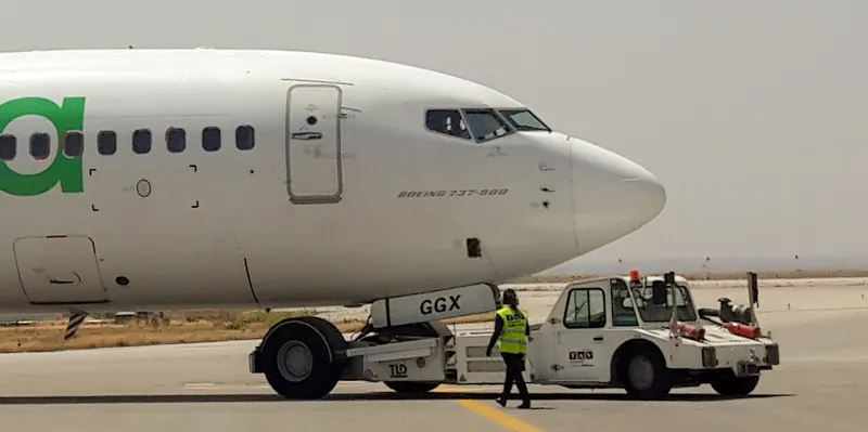
- Pushback is when an aircraft is pushed backwards away from the airport gate by vehicles called tugs or tractors.
- Closer to departure, an aircraft tug will park right in front of the nose wheel.
- The tug might be directly attached to the plane's nose gear with a tow bar, or could be a "wheel-lift" tug. These tugs cradle the nose gear, then lift it up before moving the plane. That gives the tug driver control over the plane's direction during pushback.
- New taxi technologies are appearing, like pilot-controlled tugs, and electric motors mounted to the plane's landing gear. Both promise to save fuel, and reduce airport noise.
5) Learn about take-off power, tire design, rolling resistance, tire pressure and brake forces when landing.
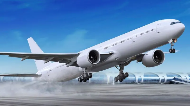
Take-off Power :-
- On take-off, in order to position the aircraft to a safe height away from terrain and obstacles (i.e. a flight path of maximum height and minimum ground distance desired).
- the engine thrust is set to a high ‘take-off power’ setting (although this is not necessarily full power) and the aircraft attitude is pitched up to maintain a specific speed.
- Once the ‘safe height’ is reached the engine thrust can therefore be reduced to a more appropriate setting and the aircraft flight path can be changed to a more appropriate flight path.
Tire Design :-
- They help to absorb the shock of landing and provide cushioning. It also provides the necessary traction for braking and stopping of an aircraft.
- An aircraft tyre is designed to withstand extremely heavy loads while landing, take off, taxing, and parking. The number of wheels required for aircraft increases with the weight of the aircraft, as the weight of the aeroplane needs to be distributed more evenly.
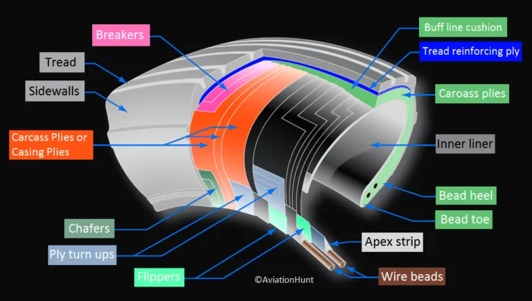
The technical aspects of the tire are discussed below,
Tread :-
- The tread is made of rubber mixed with other additives to obtain the desired level of toughness, durability, and resistance to wear.
- The tread pattern is designed to aircraft operational requirements, with the ribbed tread design used widely due to its good traction under varying runway conditions.
Sidewall :-
- The sidewall is a protective layer of rubber that covers the outer casing ply.
- It extends from the tread edge to the bead area.
Tread Reinforcing Ply :-
- One or more layers of fabric that strengthens and stabilizes the tread area for high-speed operation.
- It also serves as a reference for the buffing process when tires are rethreaded.
Buff Line Cushion :-
- The buff line cushion is made of rubber compound to enhance the adhesion between the tread reinforcing ply and the breakers or casing plies.
- It is of sufficient thickness to allow for the removal of the old tread when the tire is rethreaded.
Breakers :-
- Breakers are reinforcing plies of rubber-coated fabric placed under the buff line cushion to protect casing plies and strengthen and stabilize the tread area.
- They are considered an integral part of the casing construction.
Casing Plies :-
Alternate layers of rubber-coated fabric (running at opposite angles to one another) provide the strength of the tire.
Wire Beads :-
- Hoops of high tensile strength steel wire that anchor the casing plies and provide a firm mounting surface on the wheel.
- The outer edge of the bead that fits against the wheel flange is called the bead heel. The inner bead edge is called the bead toe.
Apex Strip :-
A wedge of rubber affixed to the top of the bead bundle.
Flippers :-
Layers of rubberized fabric that help anchor the bead wires to the casing and improve the durability of the tire.
Ply Turn-ups :-
The casing plies are anchored by wrapping them around the wire beads, thus forming the ply turn-ups.
Chafer :-
A protective layer of rubber and/or fabric located between the casing plies and wheel to minimize chafing.
Liner :-
- In tubeless tires, the liner is a layer of low permeability rubber that acts as a built-in tube and restricts gas from diffusing into the casing plies.
- In tube-type tires, a thinner liner is used to prevent tube chafing against the inside ply.
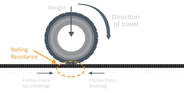
Rolling Resistance :-
- Rolling Resistance sometimes called as rolling friction or rolling drag, is the force resisting the motion of the body rolls on a surface.
- Another cause of rolling resistance lies in the slippage between the wheel and the surface, which dissipates the energy.
- For all the moving objects there will be rolling resistance which varies according to the tyre pressure and conditions.
- The formula for rolling resistance is given by,
`F_(rr) = C_(rr)*m*g`
Tire Pressure :-
- Aircraft tiresgenerally operate at high pressures, up to 200 psi (14 bar; 1,400 kPa) for airliners, and even higher for business jets.
- If the tire pressure is more than the nominal pressure it would lead to inflation because of the external pressure (load), because the aircraft tire is designed to withstand extremely heavy loads for shorter duration.
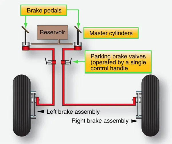
Brake Forces :-
- While landing the airplane and then braking it is a big real time challenge for the pilot because he’s is at high risk.
- The pilot should not apply sudden full brakes because it would lead to failure as the aircraft will be running at high speed with greater forces.
- The brakes should be applied gradually then after reducing the speed and forces it is advisable to apply complete braking.
6) With necessary assumptions, calculate the force and power required to push / pull an aircraft by a towing vehicle.
To tow an aircraft a towing vehicle will be used, so in order to calculate the force and power we need to calculate them individually for aircraft and towing vehicle.
Total Power / Force = Aircraft Power / Force + Towing Vehicle Power / Force
FOR AIRCRAFT :-
Parameters :-
- Span = 10.688 m
- Length = 7.62 m
- Total Area = Span*Length = 81.29 m^2
- Gravity = 9.81 m/s^2
- Co-efficient of Drag = 0.021
- Final Velocity = 10 m/s
- Initial Velocity = 0 m/s
- Acceleration Time = 15 s
- Mass = 40000 Kg
- Rolling Resistance Co-efficient = 0.03
- Density of Air = 1.225 Kg/m^3
Force Calculation :-
Rolling Resistance,
RR = `μ_(rr)`*m*g
RR = 0.03*40000*9.81
RR = 11772 N
Aerodynamic Drag,
AD = 0.5*rho*c_d*A*v^2
AD = 0.5*1.225*0.021*81.29*(10*10)
AD = 104.559 N
Acceleration Force,
AF = m*a
AF = 40000*
AF = 40000*
AF = 26666.66 N
Total Resistive Forces,
Total Force (Airplane) = RR + AD + AF
Total Force (Airplane) = 11772 + 104.559 + 26666.66
Total Force (Airplane) = 38543.22 N
Total Force (Airplane) = 38.54 KN
Power Calculation :-
Power (Airplane) = Total Force*Velocity
Power (Airplane) = 38543.22*10
Power (Airplane) = 385.4 KW
FOR TOWING VEHICLE :-
Parameters :-
- Total Area = 6.7 m^2
- Gravity = 9.81 m/s^2
- Co-efficient of Drag = 0.45
- Final Velocity = 10 m/s
- Initial Velocity = 0 m/s
- Acceleration Time = 15 s
- Mass = 9000 Kg
- Diameter of the wheel = 0.6858 m
- Radius of the wheel = 0.3429 m
- Rolling Resistance Co-efficient = 0.01
- Density of Air = 1.225 Kg/m^3
Force Calculation :-
Rolling Resistance,
RR =`μ_(rr)` *m*g
RR = 0.01*9000*9.81
RR = 882.9 N
Aerodynamic Drag,
AD = 0.5*rho*c_d*A*v^2
AD = 0.5*1.225*0.45*6.7*(10*10)
AD = 184.668 N
Acceleration Force,
AF = m*a
AF = 9000*
AF = 9000*
AF = 6000 N
Total Resistive Forces,
Total Force (Towing Vehicle) = RR + AD + AF
Total Force (Towing Vehicle) = 882.9 + 184.668 + 6000
Total Force (Towing Vehicle) = 7066.668 N
Total Force (Towing Vehicle) = 70.66 KN
Power Calculation :-
Power (Towing Vehicle) = Total Force*Velocity
Power (Towing Vehicle) = 7066.668*10
Power (Towing Vehicle) = 70666.68 W
Power (Towing Vehicle) = 70.66 KW
TOTAL FORCE & POWER :-
Force,
Total Force = Total Force (Aircraft) + Total Force (Towing Vehicle)
Total Force = 38.54 + 70.66
Total Force = 109.2 KW
Power,
Total Power = Total Power (Aircraft) + Total Power (Towing Vehicle)
Total Power = 385.43 + 70.66
Total Power = 456.06 KW (Required at velocity of 10 m/s)
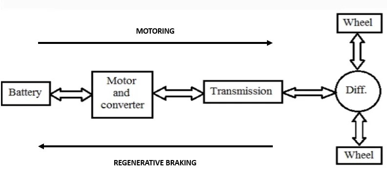
7) Design an electric powertrain with type of motor, it’s power rating, and energy requirement to fulfil aircraft towing application. Estimate the duty cycle range to control the aircraft speed from zero to highest. Make all required assumptions. Prepare a table of assumed parameters. Draw a block diagram of powertrain.
EVALUATING THE DUTY CYCLE :-
We have got the total power for towing at a velocity of 10 m/s as 456.06 KW.
We need to calculate the torque at the wheels,
WKT,
Torque = (F_t*r)/G
Where,
F_t - Tractive Force
r - Radius
G - Gear Ratio
Parameters we have considered r = 0.3429 m & G = 9.
Now,
Torque = (F_t*r)/G
Torque = (70660*0.3429)/9
Torque = 2692.14 N-m
So the torque required to move the airplane is 2692.14 N-m
We need to select the motor to find the duty cycle, so I had considered a WEG motor having the above required power and torque rating.
Parameters of the motor are,
Efficiency = 0.961 or 96.1 %
Rated Voltage = 440 V
Rated Power = 480 KW
Now,
Efficiency = `P_(OUT)/P_(IN)`
0.961 = `456.12/P_(IN)`
P_in = 474.63 KW
The input power to be given to the motor is 474.63 KW to deliver output power of 456.12 (in accounting the losses).
In general, the current (I) remains constant throughout the circuit. The voltage is being varied all the time, so to find out the duty cycle we have to make a relationship between input and output (Voltage & Current).
WKT,
Power = Voltage (V) * Current (I)
Current (I) = Power/Voltage (V)
Then
I_in = `P_(IN)/V_(IN)`
I_out = `P_(OUT)/V_(OUT)`
WKT – I_in = I-out,
`P_(IN)/V_(IN) = P_(OUT)/V_(OUT)`
`V_(OUT)/V_(IN) = P_(OUT)/P_(IN)`
Duty Cycle (D) = `P_(OUT)/P_(IN)`
Duty Cycle (D) = `456.12/474.63`
Duty Cycle (D) = 0.961 (or) 96.1 %
Here I’m considering that the time required to flow the required amount of power is 1 min (60 sec).
Energy Required,
Energy = Power*Time
Energy = 456.12*60
Energy = 27367.2 KJ
Energy = 7.62 kWh
POWERTRAIN BLOCK DIAGRAM :-
ASSUMED PARAMETERS :-
- No motor and transmission losses
- Time taken to deliver the power of 456.12 KW is 1 min (60 sec)
- Radius = 0.349 m and Gear Ratio = 9.
- The inverter, motor and battery are operating at 100 % efficiency.
- Motor Efficiency = 96.1 %