Project-1: Powertrain for aircraft in runways
Part A)1.- Aircraft Gross Weight:The aircraft gross weight is the total aircraft weight at any moment during the flight or ground operation.An aircraft's gross weight will decrease during a flight due to fuel and oil consumption. An aircraft's gross weight may also vary during a flight due to payload dropping .
At the moment of releasing its brakes, the gross weight of an aircraft is equal to its takeoff weight. During flight, an aircraft's gross weight is referred to as the en-route weight or in-flight weight.
1.Narrow body aircraft:
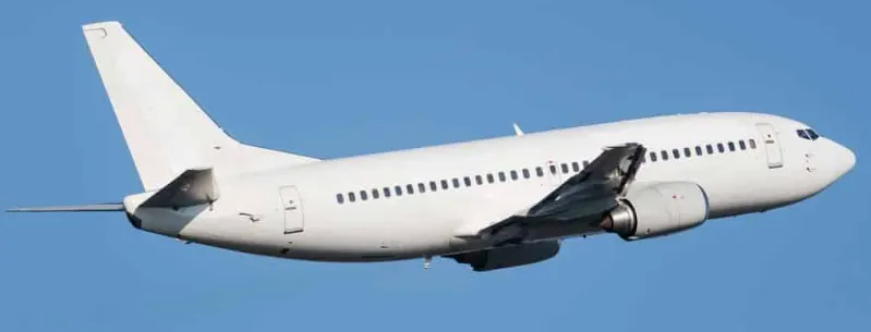
Narrow body aircraft are also known as single-aisle aircraft since they allow seating in a single row and have a cabin with a diameter of about three to four meters. This allows for up to 6 abreast seating and down to 2-abreast.
The highest seating capacity is 295 passengers. This only occurs with the Boeing 757-300. The size of the fuselage in a narrow body airplane allows passengers to stand and walk around, but not with much autonomy. There are many executive airlines that utilize narrow airplanes with luxury interiors like the Airbus 318 and the Airbus 319.
Weight =20,000kg to 40,000kg
2.Powered Lift aircrafts:
A powered lift aircraft takes off vertically under engine power but uses a fixed wing for horizontal flight. These aircraft do not need a long runway to take off and land, like helicopters , but they have a speed and performance similar to standard fixed wing aircraft in combat or other situations.
Weight : 160 kgs
3.Fighter Aircraft
A fighter aircraft, often referred to simply as a fighter, is a military fixed wing aircraft designed primarily for air to air combat against other aircraft. The key performance features of a fighter include not only its firepower but also its high speed and manuverability relative to the target aircraft.
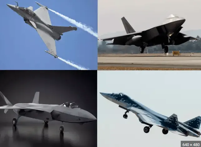
Weight : 13500 kgs
4.Transport Planes :
Military transport aircraft or military cargo aircraft are used to airlift troops, weapons and other military equipment to support military operations. Transport aircraft can be used for both strategic and tactical missions, and are often diverted to civil emergency relief missions.
Weight : 250,000 kgs
5.Aerobatic Planes
An aerobatic aircraft is an aerodyne (a heavier-than-air aircraft) used in aerobatics, both for flight exhibitions and aerobatic competitions
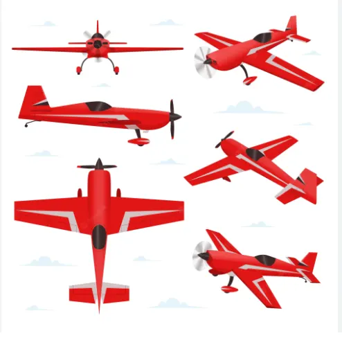
Weight : 771 kgs
6.Glider planes:
Glider is a fixed wing plane that is supported in flight by the dynamic reaction of the air against its lifting surfaces, and whose free weight does not depend on an engine. Most gliders do not have an engine, although motor glider have small engines for extending their flight when necessary by sustaining the altitude (normally a sailplane is on a continuously descending slope) with some being powerful enough to take off self launch.
Weight of Glider planes : 110 kg - 200 kg
2). Difference between ground speed and air speed:
| Ground Speed | Air speed |
| Ground speed is the airplane’s speed relative to the surface of the Earth | Airspeed is the speed relative to the air it is flying in. |
| Ground speed is what determines how fast an aircraft will get to its destination | Airspeed is what determines whether there is enough airflow around an aircraft to make it fly |
| Ground speed is simply the sum of airspeed and wind speed. | It is independent of ground speed. |
Airspeed is the vector difference between the ground speed and the wind speed.
- Airspeed = Ground Speed - Wind Speed
On a perfectly still day, the airspeed is equal to the ground speed. But if the wind is blowing in the same direction that the aircraft is moving, the airspeed will be less than the ground speed.
3). Why is it not recommended to use aircraft engine power to move it on the ground at Airport:
Towing is coupling two or more objects together so that they may be pulled by a designated power source.
Although many aircraft are capable of moving themselves backwards on the ground using reverse thrust (a procedure referred to as a powerback), the resulting jet prop might cause damage to the terminal building or equipment. Engines close to the ground may also blow sand and debris forward and then suck them into the engine, causing damage to the engine. A towing vehicle is therefore the preferred method to move the aircraft away from the gate.
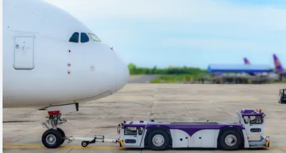
To not use the aircraft engine is typically done due to the following reasons:
- The jet blast from the engines can damage the terminal building and nearby equipment. It can even throw away people standing nearby.
- Engines can blow sand and debris.
- Engines can suck in sand and debris which can cause serious damage to the engine.
- It is easier for the truck driver to see the surroundings better than the pilot sitting in the cockpit with limited windows.
- The plane engines are very loud. This noise can add up substantially when multiple planes are moving around the airport. It won't be a pleasant experience for people sitting inside the terminal.
- It saves fuel. Virgin Atlantic had proposed a new system in which the pushback trucks will push the plane all the way to the runway to save fuel and reduce impact on nearby environment.
4).Taxiing is the movement of an aircraft on the ground, under its own power, in contrast to towing or push-back where the aircraft is moved by a tug.
The power for taxiing comes from the engines itself. If it is a propeller powered aircraft, the propeller provides thrust and pulls the aircraft, like it would in air. If it is a jet engine, the exhaust air that comes out of the engine creates a forward force due to Newton's third law and moves the airplane.
Airliners have nose wheel steering, controlled by a cockpit control called a tiller. The tiller allows nose wheel to rotate at quite extreme angles making tighter turns possible. It also reduces the fuel consumption as you do not need much engine power during taxiing. If rudders were used, the power has to be increased to make sure sufficient air flows over the rudder surface to make it effective.
Once on the take off roll and the airplane gains sufficient speed i.e. enough air flows over the rudders, pilots go back to using the rudder pedals to maintain the centre line.
Some large airplanes with multi wheel main gears have a tendency to scrub the tyres on the tarmac when nose wheel is steered. To counter this problem, an automatic main gear steering is inbuilt in the aircraft. This makes the main gears turn the opposite direction to that of the nose wheel, greatly decreasing the wear on the tyres.
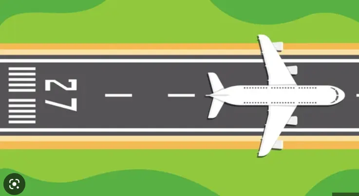
Small general aviation aircraft uses the rudder for turns during taxi. They don't have a separate control for nose wheel. In such airplanes, to make tighter turns, you could use differential braking. That is, if you want to make a tight turn for example to the left, you would push the upper part of your left rudder pedal which would apply left braking. This allows the airplane to make a sharper turn to the left.
5). Take off power, tyre design, rolling resistance, tyre pressure, brake forces when landing:
a.Take off Performance :
Take off performance can be predicted using a simple measure of the acceleration of the aircraft along the runway based on force equilibrium.
The forces involved will be,
T – Thrust of propulsion system pushing aircraft along runway.
D – Aerodynamic Drag of vehicle resisting the aircraft motion.
F – Rolling resistance friction due to the contact of wheels or skids on the ground.
During take-off run the imbalance in these forces will produce an acceleration along the runway.
dv/dt = (T - D - F) /m
The procedure for take-off will be that the vehicle will accelerate until it reaches a safe initial flying speed. The pilot can then rotate the vehicle to an attitude to produce climb lift and it will ascend from the ground. The determination of this safe flying speed or rotation speed, VR, is a critical factor in determining take-off performance.
For safety reasons VR is usually determined as being 1.1 × VSTALL
VSTALL : is the lowest speed that the aircraft can be flown before the airflow starts to separate from wings as the angle of attack becomes too great. The wing is assumed in this case to be in take-off configuration or "clean".
It can be calculated based on knowledge of the aircraft take-off configuration and hence the maximum achievable lift coefficient CL(max). As shown in the previous section , to maintain level flight the lift produced must equal the weight, hence the stall speed can be calculated as,
Vstall=sqrt{W/((1/2)*Cl(max)*ro*S)}
b).Tyre Design: An aircraft tyre is designed to withstand extremely heavy loads while landing, take off, taxing, and parking. The number of wheels required for aircraft increases with the weight of the aircraft, as the weight of the aeroplane needs to be distributed more evenly.It also provides the necessary traction for braking and stopping of an aircraft.
Carcass plies(layers of rubber) are used to form the tire.
An aircraft tyre is constructed for the purpose it serves.
- They support the weight of an aircraft while it is on the ground.
- It also provides the necessary traction for braking and stopping of an aeroplane.
- Tyre also helps to absorb the shock of landing and provide cushioning the roughness of takeoff, roll-out, and taxi operations.
Retreading – Retreading is methods of restoring a worn tyre by renewing the tread area or by renewing the tread area plus one or both sidewalls. Repairs are included in the tyre retreading process.
Load Rating – Load rating is the maximum permissible load at a specified inflation pressure.
Ply Rating – Ply Rating is used to identify the maximum recommended load rating and inflation pressure for a specified tyre. It is an index of tyre strength.
Speed Rating – The speed rating is the maximum takeoff speed to which the tyre has been tested.
Skid Depth – Skid depth is the distance between the tread surface and the deepest groove as measured in the mould.
Aircraft tyres must have an approved speed and load rating and have sufficient clearance when retracted through landing gear to allow for tyre growth. Tyre growth is the increase in the size of the tyre due to centrifugal forces at high speed.
Aircraft tyres may be Tube-type or Tubeless:
Tubeless tyres are more advantageous over tube-type. There is no longer the use of tube-type tyre in recent aviation. Nowadays all airliners are using tubeless tyres. Tubeless that are meant to be used without a tube.
Aircraft tyres may be Radial or Bias
Almost all airliners are using Radial tyre. Bias is an older design, and it’s mainly used for road vehicles. Radial tyres have the word RADIAL on the sidewall. Radial tires are more expensive than bias-ply tyres. Radial tires are in demand because of their lower life cycle cost and long term value.
Chines are sometimes found on the nose wheels of aircraft with fuselage mounted engines. The edges of the tire sidewalls have a curved protrusion (chine) that deflects standing water outward to reduce water ingestion into the engines. Tyres may have chines on one or both sides, depending on the number of nose tyres on the aircraft.
c)Rolling resistance:The friction between aircraft and runway will be proportional to the normal force exerted by the aircraft on the runway.
The rolling resistance can be expressed as:
Fr = c W
where Fr = rolling resistance or rolling friction (N, lbf)
c = rolling resistance coefficient - dimensionless (coefficient of rolling friction - CRF)
W = m ag
= normal force - or weight - of the body (N, lbf)
m = mass of body (kg, lb)
ag = acceleration of gravity (9.81 m/s2, 32.174 ft/s2)
The normal force will be the difference between Weight of aircraft and Lift, the friction coefficient will be typically of a magnitude of 0.02 for a standard tarmac runway.
d)Tyre pressure:
Aircraft tires generally operate at high pressures, up to 200 psi (14 bar; 1,400 kPa) for airliners, and even higher for business jets. The main landing gear on the Concorde was typically inflated to 232 psi (16.0 bar), whilst its tail bumper gear tires were as high as 294 psi (20.3 bar).
e).Braking force:Stopping an aircraft landing at 180-200 mph requires a lot of braking force. To do this, the aircraft has brake unit on each of the wheels on the maingear assembly. On landing, pilots should use aerodynamic braking by applying extra back-pressure on the stick or yoke. Applying the brakes at too high a speed could burn the tires, wear out the brakes, or result in a ground loop or swerve.
In addition to the brakes, there are two other systems which help slow the aircraft down on landing. The spoilers and the reverse thrust.
Spoilers:Have you noticed the large panels on the top of the wings raise up on touch down? These are the called the spoilers as they literally spoil the airflow over the wing. This dumps any remaining lift the wings are generating, allowing the wheels to take all the weight and achieve maximum efficiency from the brakes.
Reverse thrust:The final part of the braking process comes from reverse thrust. Just after we have touched down, we pull two levers on top of the thrust levers to engage the reverse thrust, a sort of “reverse gear” for jet engines.
- There are two stages of reverse thrust — idle reverse and max reverse.
- Idle reverse is used on most landings and max reverse is used when the landing performance requires it, normally when the aircraft is landing at hot or high elevation airfields.
PART B:
6). A To push or pull an aircraft by a towing vehicle, 3 type of forces will act on that vehicle.
- Rolling resistance force
- Aerodynamic dragforce and
- Hill climbing force.
(i)Rolling resistance(Frr):
Rolling resistance is the force resisting the motion when a body rolls on a surface. It is the friction force that is needed to be overcome to move a vehicle. The kinetic energy of the wheels is partially converted into heat. The rolling resistance is proportional to the normal force perpendicular to the rolling wheel and is approximated by the rolling resistance coefficient urr. Therefore, Equation that can be used for the rollingresistance force of the entire system is-
Frr = urr * m * g ---------(1)
where, urr= Rolling resistance co-efficient
m= Total mass of the vehicle (vehicle mass + payload) in kg
g = gravitational constant , that is 9.8 m/s^2.
The friction force for the puller can be calculated to:
Fff=uff*m*g ----------(2)
where Fff= frictional force (N, lb)
uff = friction coefficient
W = weight (N, lbf)
mf = friction mass (kg)
Here in this case for towing vehicle for aircraft urr= 0.013.
(ii) Aerodynamic drag force(Fad) :
Aerodynamic drag force is the force which is required to keep a vehicle moving. There are two component of this force , one is shape drag (due to the shape of the vehicle) and another is skin friction (due to friction between air and skin of the vehicle). When the vehicle moves the velocity of air near boundary is higher than the air surrounding. Both the tug and the aircraft will experience some aerodynamic drag.
Fad = (1/2) * ρ * V^2 * A * (Cd_t + Cd_a)
where, ρ = Air density, that is normally 1.25 kg/m^3
A = Frontal area of the vehicle in m^2
Cd_t = Air drag co-efficient of towing vehicle (It depends on frontal area,shape, protrusions, ducts, air passage etc.)
Cd_a = Air drag co-efficient of aircraft (Itdepends on frontal area, shape, protrusions, ducts, air passage etc.)
v =Velocity of the vehicle in m/s
With regard to the drag equation, the term A simply refers to some reference area. For airplanes, this is generally the planform area of the wing The designers design an aircraft in such a way that the reference area is optimal. So, for calculation this has been neglected.
In this case air drag co-efficient for towing vehicle(Cd_t)= 0.5 and for aircraft or payload(Cd_a)= 0.045.
(iii) Hill climbing force(Fhc) :
Hill climbing force is the force needed to move the vehicle in up gradient. To Hill Climbing force the expression of the equation isgiven below-
Fhc = m * g * sin(theta)
where, m = Total mass of the vehicle(vehicle mass + payload) in kg
g = Gravitational constant that is 9.8 m/s^2
Theta = up gradient angle or inclination angle in radian
In this case up gradient angle(theta)= 0, as there is no inclination.
Hill climb force is zero in this case.
Now the tractive force or the pulling force required by the tow will be:
Pulling force = Drag force + friction force + Rolling resistance force
Now let us consider aircrafts with the following specifications :
Now as we have seen that various kinds of planes have different weights ,the amount of pulling force also will be different.Therefore we will consider a range of weight :
Range of weight = 200 kgs - 250000 kgs '
The towing speed considered is 2.5 m/s
Area range : 20 - 100 m^2
Coefficient of rolling resistance : 0.02
Coefficient of friction : 0.13
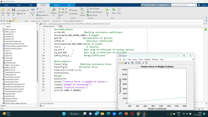
6).B Taking data as per assumptions:
Urr(rolling resistance coefficient)=0.02
mass of plane = 25000
g=9.81
Uff(frictional coefficient)=0.13
mass of the towing vehicle= 5000
Air density=1.225
Drag coefficient=0.545
area=20
Velocity=2.5 m/s
7). Electric powertrain with type of motor:
Let us Assume:
Weight of the Aircraft =25000kg
Rolling Resistance Coefficient of an aircraft tire =0.02
Wight of the Towing Tractor=5000kg
Rolling Resistance Coefficient of Towing Vehicle =0.13
The Velocity of the Aircraft while Towing=9KMPH=2.5m/s
The density of Air medium=1.225 kg/m^3
The Frontal area of the Aircraft=20 'm^2
The Coefficient of Drag of the Aircraft =0.545
Towing Tractor Gear ratio(G-for high torque output)=11
Towing Tractor tyre radius(r)=0.5 m
Operational time of the Towing for one cycle=0.25 Hours (15min)
Power converters used Bidirectional DC-DC Boost Converter
We taking calculated values from the above equation
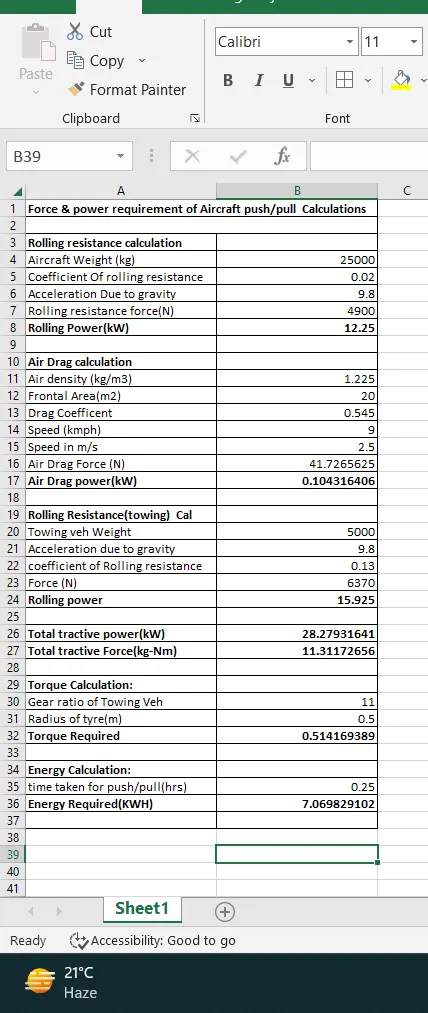
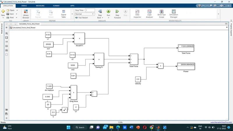
The total force required for a towing vehicle to push the aircraft is =11.4 KN=11323.22656N
Power required for the towing vehicle to pull the aircraft=28.4KW=28308.0664 W
Torque Required with the wheels of towing vehicle to push the aircraft
Torque=force *(radius/Gear ratio)
Torque= 11.4 *(0.5/11)
Torque=0.51818 KN/m
Therefore the Torque required the towing vehicle to push the aircraft =0.51818KN-m
- i) Energy Requirements:The Energy requirement for an EV similar to the Towing vehicle to Push/Pull the aircraft is calculated on the Basis of Time
Let, Energy =Power x Time taken by the towing vehicle to push-pull the aircraft
Energy=28.4 x 0.25
Energy =7.1 KWH
Therefore power required for one single towing is=7.1 KWh
Therefore, the battery must store the energy 7.1 KWH and deliver the energy throughout the run time for the motor to produce the 0.51818 KN-m of torque. Thus the storage of energy in batteries with high-performance Ultracapacitors are selected to fulfil the required power delivery.
Motor Selection:
Here we have selected a Permanent-Magnet Synchronous Motor (PMSM) type that has a power rating of 28.4KW and with the gear ratio and the transmission, it should be able to deliver 0.51818 KN-m of torque instantaneously.
Motor Parameters:
Type=PMSM
Model No.=APEV80-12(16)
Phase=3
Application Electric bus,Truck,passenger,car
DC Voltage=200-750V
Pole=12
Direct Current Voltage (VDC)=540V
Rated current (A)=255
Peak Current (A)=650
Rated Power (kW)-100
Peak Power (kW) =220
Rated Speed (RPM)=1650
Peak Speed (RPM)-3.300
Rated Torque (Nm)-868
Peak Torque (Nm) =3.000
BEMF (VAC)/rpm=660/2401
Insulation Grade-H Protection
Class IP67
Cooling Water
Weight (Kg)=260
The efficiency of motor=90 % (Assumed Parameter)
Duty Cycle:
Here in this case the Duty cycle of the electric power train is calculated by the output power by the input power By this, we get the efficiency of the duty cycle.
Duty Cycle = Output Power /Input Power
We know that.
Output Power= 28.4 kW
Input Power =Rated Motor Power / Motor Efficiency-
Input Power =75/0.9
Input Power=83.333kW
Then
Duty Cycle =28.4/83.33
Duty Cycle =0.340
Duty Cycle =34%
Therefore the Efficiency of the Duty cycle that we get for this electric power train is=0 to 34%
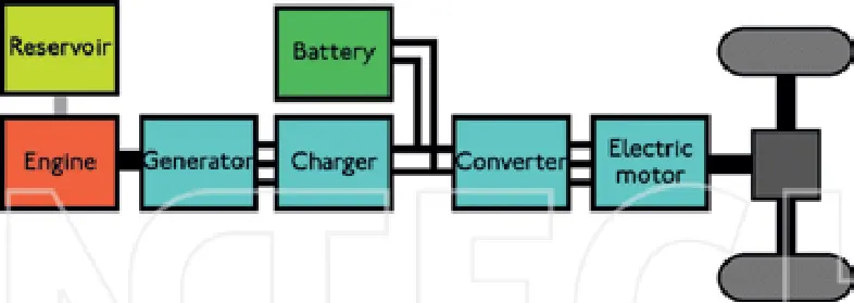
Block Diagram:
Simulink Design with assumed Parameters:
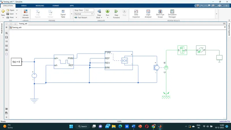
The following components were used :
1.PWM Module : Pulse width modulation speed control works by driving the motor with a series of “ON-OFF” pulses and varying the duty cycle, the fraction of time that the output voltage is “ON” compared to when it is “OFF”, of the pulses while keeping the frequency constant.The power applied to the motor can be controlled by varying the width of these applied pulses and thereby varying the average DC voltage applied to the motors terminals. By changing or modulating the timing of these pulses the speed of the motor can be controlled.
2.Dc_Motor: The motor is a dc motor having two terminals ,the rotor R and the case c which is fixed to a stationary frame .The motor produces the amount of torque required and gives it to the gearbox.
3.Gearbox,wheel axle and Mass: The gearbox input shaft is connected to the output of the motor and is given gear ratio of 10 to produce the required torque .The gearbox gives the required torque to the wheel axle which has the mass attached to it.
7).B Design the parameters in excel sheet: