Project-1: Powertrain for aircraft in runways
Q1 TOTAL WEIGHT OF VARIOUS TYPE OF AIRCRAFTS
AIRCRAFT GROSS WEIGHT
It is The total aircraft weight at any moment during the flight or ground operation
An airgraft weight will be decreased during the flight due to the fuel and oil consumption and also due to the payload dropping
During that time when the aircraft braking is applied the gross weight of an aircraft is equal to the take off weight
TYPES OF AIRCRAFT WEIGHT
FIGHTER AIRCRAFT
It is used in the military base mainly for the air to mair combat against other aircraft it weight at 13500kgs.its major usage is mainly due to the high speed and fire power
MILITARY CARGO TRANSPORT
WEIGHT 250000kgs
These mainly used to airlift the military weapons andanother military weapons to support the army
It is also used for the civil emergency relief missions
GLIDER
It is a fixed wing plane that is supported in the flight by the dynamic reaction of the air against its lifting surface and who se free weight does not depends upon the engine
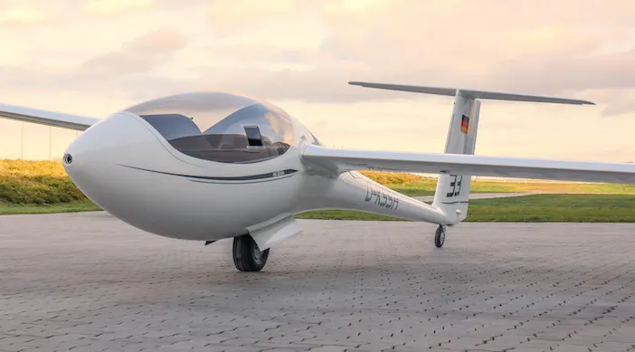
Weight of glider 110-200kgs
Q2.GROUND SPEED VS AIR SPEED
*Ground speed is the airplanes speed which is relative to the surface of the earth
*ground speed is the sum of the air speed and the wind speed
*Ground speed determines how fast the air craft wll get to its destination
AIR SPEED
*Airspeed is the speed relative to the air its flying in
*Air speed id what determines weather there is enough air flow around an aircraft to make it fly
*It is independent of the ground speed
Q3.AIRCRAFT ENGINE POWER NOT RECOMMENDED TO MOVE IN GROUND
TOWING is the concept of coupling two or more objects together so thet they may be pulled by a desingnated power source.it may be a motorized land vehicle,animal
Most of the air craft are capable of moving themselves backward on the ground using reverse thrust called as POWERBACK it is not typically done due to the following reasons
*Engine can stuck in the sand and derbris which results in the damages to the engine
*It is easier for the truck driver to see the surroundings better than the pilot sitting in the cockpit
*Theplane engines are very louder
*it saves fuel of the aircraft
*The jet blast from the engine can damage the terminal building and nearby equipments
Q4 MOVEMENT OF AIRCRAFT ON GROUND
Movement of the aircraft on the ground under the own power is known as TAXiING.in the contrast of towing if it incase of propeller powered aircraft the propeller provides the trust and pull the aircraft
If it is an jet engines the exaust air that comes from the engine creates an forward force due to the newtons third law
Aircraft has nose wheel steering which is fully controlled by the cockpit called thre TILLER .this makes the turns possible and also reduces the fuel consumption.if the rudders were used the power has been in creased to make more sufficient air flow.
After the aircraft attains the sped to take off the pilot go back to using the rudders pedal to maintain the centre line .in some cases an automatic gear steeing is builtinorder to scrub the tyres on the tarmac when nose wheel is steered.
b.Tyre Design of aircrafts :
When it comes to safety, tyres are one of the most important components of aircraft. They help to absorb the shock of landing and provide cushioning. It also provides the necessary traction for braking and stopping of an aircraft.
An aircraft tyre is designed to withstand extremely heavy loads while landing, take off, taxing and parking. The number of wheels required for aircraft increases with the weight of the aircraft, as the weight of the aeroplane needs to be distributed more evenly.
Carcass plies are used to form the tire. They are sometimes called casing plies. An aircraft tyre is constructed for the purpose it serves.
Unlike an automobile or truck tyre, it does not have to carry a load for a long period of continuous operation. However, an aircraft tyre absorbs the high impact loads of landing and also it’s operating at high speeds for a short time when required.
Retreading – Retreading is methods of restoring a worn tyre by renewing the tread area or by renewing the tread area plus one or both sidewalls. Repairs are included in the tyre retreading process.
Load Rating – Load rating is the maximum permissible load at a specified inflation pressure.
Ply Rating – Ply Rating is used to identify the maximum recommended load rating and inflation pressure for a specified tyre. It is an index of tyre strength.
Speed Rating – The speed rating is the maximum takeoff speed to which the tyre has been tested.
Skid Depth – Skid depth is the distance between the tread surface and the deepest groove as measured in the mould.
Aircraft tyres must have an approved speed and load rating and have sufficient clearance when retracted through landing gear to allow for tyre growth. Tyre growth is the increase in the size of the tyre due to centrifugal forces at high speed.
c.Rolling Resistance :
Rolling resistance, sometimes called rolling friction or rolling drag, is the force resisting the motion when a body (such as a ball, tire, or wheel) rolls on a surface. It is mainly caused by effects; thnon elastic at is, not all the energy needed for deformation (or movement) of the wheel, roadbed, etc., is recovered when the pressure is removed. Two forms of this are hysterisis losses , and permanent plastic deformation of the object or the surface (e.g. soil). Another cause of rolling resistance lies in the slippage between the wheel and the surface, which dissipates energy. Note that only the last of these effects involves friction, therefore the name "rolling friction" is to an extent a misnomer.
The rolling resistance can be expressed as
Fr = c W (1)
where
Fr = rolling resistance or rolling friction (N, lbf)
c = rolling resistance coefficient - dimensionless (coefficient of rolling friction - CRF)
W = m ag
= normal force - or weight - of the body (N, lbf)
m = mass of body (kg, lb)
ag = acceleration of gravity (9.81 m/s2, 32.174 ft/s2)
|
Rolling Resistance Coefficient |
|
|
|
c |
cl (mm) |
|
|
0.001 - 0.002 |
0.5 |
railroad steel wheels on steel rails |
|
0.001 |
bicycle tire on wooden track |
|
|
0.002 - 0.005 |
low resistance tubeless tires |
|
|
0.002 |
bicycle tire on concrete |
|
|
0.004 |
bicycle tire on asphalt road |
|
|
0.005 |
dirty tram rails |
|
|
0.006 - 0.01 |
truck tire on asphalt |
|
|
0.008 |
bicycle tire on rough paved road |
|
|
0.01 - 0.015 |
ordinary car tires on concrete, new asphalt, cobbles small new |
|
|
0.02 |
car tires on tar or asphalt |
|
|
0.02 |
car tires on gravel - rolled new |
|
|
0.03 |
car tires on cobbles - large worn |
|
|
0.04 - 0.08 |
car tire on solid sand, gravel loose worn, soil medium hard |
|
|
0.2 - 0.4 |
car tire on loose sand |
|
d.Tyre Pressure :
Car tyres aren’t just unsafe when they’re old and worn out – you need to ensure you know what tyre pressure you have in your tyres when you drive it because there are critical safety and economic implications.
Car tyre pressure is a measurement of how much air is in your pneumatic tyre, and ensures the tyres wear evenly and maintain the correct level of grip on the road surface. This is commonly expressed as PSI, or pounds-per-square-inch.
Q6.FORCE AND POWER CALCULATION
To propell any vehicle we need to overcome several opposite forces acting on the same vehicle .
The actual forces acting on the vehicle varies from place to place.
Let us consider the regular runway the oposite forces are acting to propel the vehicle are
Rolling resistance force (Frr)
and aerodynamic drag force.(Fad)
there is no grade so hill climbing force (Fhc)is neglected.
The sum these forces is actual or total force (Fte) to overcome to propel the vehicle.
Frr=m.g.μrr;
Fad=1/2*ρACdv^2;
where,
m-mass of the vehicle(kg)
g-gravitational constant.(kg/m^2)
μrr-rolling resistance
ρ-air density(kg/m^3)
A-frontal area(m^2)
Cd-aero drag coefficient
v-velocity of the vehicle(m/s)
Fte=Rolling resistance force (Frr)+aerodynamic drag force.(Fad)
Fte=mgμrr+1/2*ρACdv^2
assume any vehicle(aircraft ):
some of the asumptions are :
mass of the aircraft (ma)=580000kg;
mass of the towing vehicle=1000kg;
gravitational constant(g)=9.81m/s^2;
rolling resistance(μrr)=0.002;
air density(ρ)=1.125kg/m^3;
frontal area (A)=150m^2;
aero drag coefficient(Cd)=0.025;
velocity(v)=21.6km/hr=6m/sec
Frr=mgμrr
=(580000)*9.81*0.05
=11379.6N
Fad=1/2*ρACdv^2
=0.5*1.125*150*0.025*4^2
=33.75N
Fte=mgμrr+1/2*ρACdv^2
=11413.35N
force required to pull or push the vehicle Fte=7909.9488N
torque at the wheels =force *radius
=11413.35*0.2(tire radius=0.2m)
=2282.67Nm
power required to pull the vehicle;
we know;
power(p) =force *velocity
=Fte*v
=11413.35*4
=456534watts
=45.6534kw
The power required to propell the vehicle is 45.6534kw.
Q.6.B.MODAL HAS GIVEN BELOW
7 DESIGHN OF A ELECTRIC POWER TRAIN
From the forces acting on the vehicle we calculated the power required the vehicle.
The power required to propell the vehicle is 45.653kw.
This power is the output power of the motor.
In order to select the power rating of the machine we need to consider the efficiency accepct .
Because the machine consists of different types of losses .
we know that
input power =outpower +losses in machine
efficiency (η)= outpower/inputpower
let us assume the machine efficiency is 85%
then the input power is calculated as
inputpower =outpower/efficiency (η)
=45.853kw/0.85
=53.94kw
From this we can select a 55kw dc motor is sufficient for the powerr train.
If we consider the particular motor to operate for a 1hr then the energy for the machine is given by
energy = power *time
=45.863*3600
=165.070kwh or 165070wh
Duty cycle range to control the aircraft speed from zero to highest Block diagram of powertrain :
To operate the machine at high speed the it needs max power the duty cycle will be
duty cycle=outpower /input power
=53.070/45.853
=0.85%
Block diagram of powertrain :
The power train block diagram maainly consists of ,Battery ,Motor,Motor-controller,Power-coverter & Transmission
Assumed parameters :
Here I assumed the rafale fighter aircraft ;
|
Parameter |
assumption |
|
mass of the aircraft (ma) |
580000kg |
|
mass of the towing vehicle |
1000kg |
|
rolling resistance(μrr) |
0.002 |
|
air density(ρ) |
1.125kg/m^3 |
|
frontal area (A) |
150m^2 |
|
aero drag coefficient(Cd) |
0.025 |
|
velocity(v) |
4m/sec |
|
gravitational constant(g) |
9.81m/s^2 |
Power train model designed in simulink :
The below model represents the simple powertrain model for aircraft on the run way.In general the power train consists of the battery (source), motor ,motor controller ,
This model consists of battery,four quadrant chopper dc drive (DC) The main purpose of the dc drive is it consists the controller also.
The dc 7 model is reference for the powertrain for the for aircraft on runway.
These are the plots for above powertrain :
The plot consists of the duty cycles of the contoller igbt swithes,
Armature voltage of the motor
armature current of motor
motor speed .and torque.