Project-1: Powertrain for aircraft in runways
PROJECT 1 – POWERTRAIN FOR AIRCRAFT IN RUNWAYS
Aim –
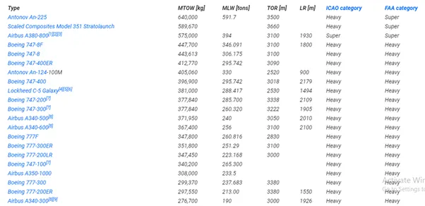
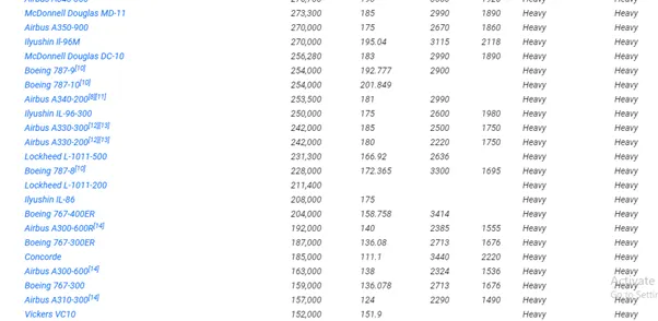
- Search & list out the total weight of various types of aircrafts.
- Is there any difference between ground speed & air speed?
- Why is it not recommended to use aircraft engine power to move it on the ground at airport?
- How an aircraft is pushed to runway when it’s ready to take off?
- Learn about take-off power, Tyre Design, Rolling Resistance, Tyre pressure, Brake forces when landing.
- With necessary assumptions calculate the force & power required to push / pull an aircraft by towing a vehicle.
- Design an electric powertrain with a type of motor, its power rating & energy requirement to fulfil aircraft towing application, estimate the duty cycle range to control the aircraft speed from 0 to highest. Make all required assumed parameters. Draw a block diagram of powertrain.
- Search & list out the total weight of various types of aircrafts.
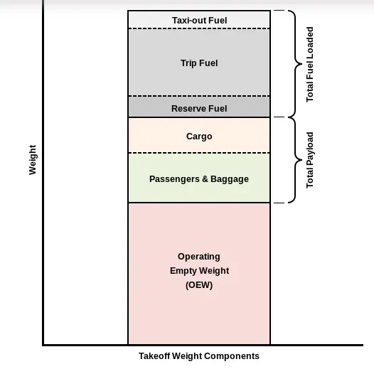
Aircraft Authorized Gross Weight Limits (also referred to as certified weight limits) are laid down in the (AFM) or Associated Certificate of Airworthiness (C of A). The Authorized weight limits that can legally be used by an operator or airline are those listed in AFM and the weight and balance manual. The Authorized weight limits are chosen by the customer/ airline and they are referred to as “purchased weight”. The operator may purchase certified weight below the max. design weight because many of the operating fees are based on the aircraft AFM maximum allowable weight values. An aircraft purchase is typically a function of the certified weight purchased.
Maximum weights established for each aircraft, by design & certification must not be exceeded during aircraft operation (ramp or taxying, take-off, en-route flight, approach & landing) & during aircraft loading (zero fuel conditions, centre of gravity positions, weight distribution) weights could be restricted on some type of aircraft depending on the aircraft handling requirements, for e.g. Aerobatic Flight Aircraft, where certain Aerobatic Manoeuvres can only be executed with a limited gross weight. In addition, the authorised maximum weight limits may be less as limited by centre of gravity, fuel density and fuel loading limits.
Manufacturer’s Empty Weight (MEW) –
It is also called Licensed Empty Weight
It is the weight of the aircraft “as built” & includes the weight of the structure, power plants, furnishing, installations, systems, & other equipment that are considered an integral part of the aircraft.
This includes baggage, passengers & usable fuel.
Zero Fuel Weight (ZFW) –
This is the total weight of the airplane and all its contents (including usable fuel), but excluding the total weight of the usable fuel on board.
As a flight progresses and fuel consumed, the total weight of the airplane reduces, but the ZFW remains constant.
Maximum Zero Fuel Weight (MZFW) is the maximum weight allowed before usable fuel and other specified usable agents (engine injection fluid & other consumable propulsion agents) are loaded.
Operating Empty Weight (OEW) –
It is roughly equivalent to Basic Empty Weight on light aircraft.
It is the basic weight of an aircraft including the crew, all fluids necessary for operation such as engine oil, engine coolant, water, usable fuel, & all operator items & equipment required for flight but excluding usable fuel but payload.
Payload –
It is the carrying capacity of an aircraft which includes cargo, people, extra fuel. In case of the commercial airliner, it may refer only revenue generating cargo or paying passengers.
Maximum Take-Off Weight (Maximum Brake Release Weight) –
The maximum weight authorized at brake release for take-off, or at the start of the take-off roll. The maximum take-off weight is always less than the maximum taxi/ramp weight to allow for fuel burned during taxi by the engines and the APU. In operation, the maximum weight for take-off maybe limited to values less than maximum take-off weight due to aircraft performance, environmental conditions, airfield characteristics (take-off field length, altitude), airspeed, maximum tyre speed, obstacle clearances, landing requirements, the maximum weight authorised for normal landing of an aircraft.
The MLW mustn’t exceed MTOW.
The operation landing weight must be limited to a weight lower than the maximum landing weight by the following reasons -
Aircraft performance requirements for a given altitude and temperature, landing field length requirements, approach and landing climb requirements.
The Maximum Permissible Weight –
It is the Maximum Weight permitted before usable fuel and other specified usable fluids are loaded in a specific sections of the airplane.
This weight of the aircraft is less than the all usable fuel and other specified usable agents.
Noise Requirements –
If the flight has been of short duration fuel may have been jettisoned to reduce the landing weight. Overweight landings requires a structural inspection or evaluation of the touch down loads before the next aircraft operation.
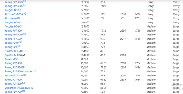
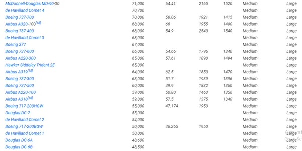
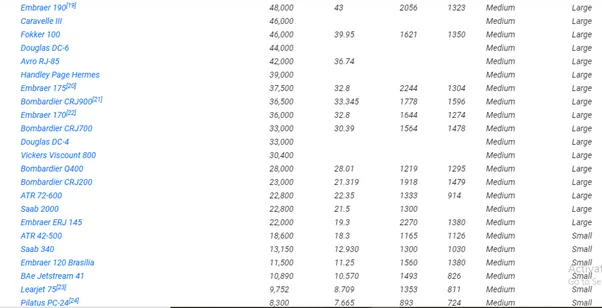

- Is there any difference between ground speed & air speed?
As we know, true airspeed is simply the speed at which the aircraft is moving relative to the air it is flying in. As such, it is also the speed at which the air is flowing around the aircraft’s winds. Ground speed on the other hand is aircraft’s relative to the ground.one thing that noted here is that it is horizontal rather than the vertical speed – an aircraft climbing completely vertical would have a ground speed at zero. In other words, while airspeed is what determines whether there is enough airflow around an aircraft is what determines whether there is enough airflow around the aircraft to make it fly, ground speed is what determines how fast an aircraft will get its attention.
Aerodynamic forces are generated by an object moving through a fluid (liquid or Gas). A fixed object in a static fluid doesn’t generate aerodynamic forces. Hot air balloons lift because of buoyancy forces and some aircraft like the Harrier use thrust to lift the vehicle, but these aren’t examples of aerodynamic lift. To generate lift the object must move through the air, or air must move past the object. Aerodynamic lift depends on the square of the velocity between the object & the air. Now things get confusing because not only can the object be moved through the air but the air itself can move. To properly define the relative velocity, it is necessary to pick a fixed reference point and measure velocities relative to the fixed point.
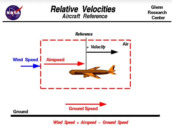
The aircraft usually operates in land as well as in air so we do not need to study their differences in ground and in air.
The difference between the ground speed & air speed is caused by the influence of the winds on the overall velocity of the aircraft.
The groundspeed and the airspeed usually changes depending on the wind component.
If we decide that there is no wind component, then Ground Speed = Air Speed.
If wind is blowing in the tail direction of an aircraft, then (Air Speed > Ground Speed)
Air Speed = Wind Component + Ground Speed.
If wind is blowing in the head direction of the aircraft then, (Air Speed < Ground Speed)
Air Speed = Ground Speed - Wind Component.
Gravity plays major role in increasing the aircraft speed while it is descending.
- Why is it not recommended to use aircraft engine power to move it on the ground at airport?
It is not recommended to use aircraft engine power to move it on the ground at airport because there are certain extreme cautions for everything around us like.
Applying thrust (gas) can create a blast behind each engine.
People, equipment, and anything else in the way can be injured or damaged from the jet blast.
Before we apply power to engines the areas in front of each engine are like other super critical factors that must be carefully negotiated.
The immediate area in front of the jet engine creates an area where people and equipment can be sucked in to the engine if anything is too close to the intake.
To avoid extreme cautions, it’s not recommended to use aircraft engine power to move it on the ground at the airport.
Also, Taxiing is the movement of the aircraft on the ground, under its own power, in contrast to Towing or Push back where the aircraft is moved by a tug. The aircraft usually moves on wheels, but the term also includes aircraft with skis or float (for water based travel).
An airplane uses taxiways to taxi from one place of an airport to another for example, when moving from hangar to the runway. The term Taxiing isn’t used for accelerating run along a runway prior to take-off, or the decelerating run immediately run after landing, which are called the take-off roll & landing rollout respectively.
- How an aircraft is pushed to runway when it’s ready to take off?
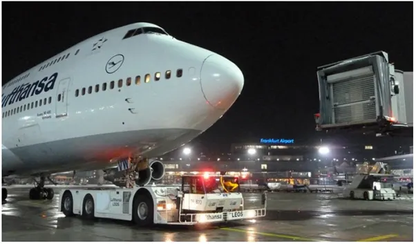
Taxiing refers to the movement of an aircraft on the ground, under its own power. he aircraft moves on wheels. An airplane uses taxiiways to taxi from one place to another.
When aircraft is ready with all the passengers and luggages for the aviation then pushback is the aviation procedure during which an aircraft is pushed backwards away from an airport gate by external power. The aircrafts always move on the ground following the yellow lines, to avoid any collision with the surrounding buildings, vehicles, or other aircrafts. The taxiing motion has the speed limit. Before making a turn, the pilot reduces the speed further to prevent the tire skids. Just like cars, there is certain list of priorities during taxiing. The aircraft that are landing or taking off have higher priority. The other aircrafts have to wait for these aircrafts before they start or continue taxiing. The thrust to propel the aircraft forward comes from its propellers/jet engines. Steering is achieved by turning a nose wheel or tail wheel; the pilot controlling the direction travelled with their feet. The use of engine thrust near terminals is restricted due to the possibility of jet blast damage. This is why the aircrafts are pushed back from the buildings by a vehicle before they can start their own engines for taxiing.
Pushbacks are carried out by special, low profile vehicles called pushback tractors/tugs.
These are heavy weighing low profile vehicles with enormous torque to do the job of pushing/pulling the large aircraft from the terminals to the runway.
The tractors are designed with extra weight purposefully to offer them enough traction to push or pull the heavy aircraft.
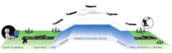
You Tube Link - https://www.youtube.com/watch?v=F077WDnB8P8
Take off –
Take off is the phase of flight in which an aircraft goes through the transition from moving along the ground (Taxiing) to flying in the air, usually starting on a runway. Usually engines are run at full power during take-off. Following the taxi motion, the aircraft stops at the starting line of the runway. Before take-off, the engines particularly the piston engines, are routinely run up at high power to check for engine related problems. This makes considerate noise. when the pilot releases the brake, the aircrafts starts accelerating rapidly until the necessary speed to take-off to achieve.
The take-off speed required varies with air density, air weight, aircraft configuration (flap/slat position) air density is affected by factors such as field elevation & air temperature.
Operations with transport category aircraft employ the concept of take-off V-speeds, V1 & V2. These speeds are determined not only by above factors affecting take-off performance but also by length and slope of the Runway. Below V1, in case of critical failures, the take-off should be aborted; above V1 the pilot continues the take-off and returns for landing. After the co-pilot calls V1, then V2 (the safe take-off speed) is called, this speed must be maintained after an engine failure to meet performance targets for rate of climb & angle of climb.
Operations with transport category aircraft employ the concept of the take-off & returns for landing, after the co-pilot calls V1. Then V2 (the safe take-off speed) is called. The speed must be maintained after an engine failure to meet performance targets for rate of climb & angle of climb.
The speeds needed for take-off are relative to the motion of the air (indicated air speed). Ahead wind will reduce the ground speed needed for take-off, as there is greater flow of air over the winds. This is why the aircrafts always take-off against the wind. Side wind is not preferred as it would disturb the stability of the aircraft. Typical take-off air speeds for Jetliners are in the 130-155 knot range (50-180mph) for a given aircraft, the take-off speed is usually directly proportional to the aircraft weight, the heavier the weight, the greater the speed needed. Some aircraft have difficulty generating enough lift at the low speeds encountered during take-off. These are therefore fitted with high-lift devices, often including flaps & slaps, which includes the camber of the wing, making it more effective at low speed. Thus creating more lift. These have to be deployed from the wing before performing any manoeuvre.
At the beginning of the climbing phase, the wheels are retracted into the aircraft & the undercarriage doors are closed. The operation is audible by the passengers as a noise coming from below the floor.
Climb –
Following take-off, the aircraft has to climb to certain altitude (30,000 ft. or 10 KM) before it can cruise at this altitude in a safe & economic way. A climb is carried out by increasing the lift of the wing supporting the aircraft until the lifting force and weight are again in balance. The increase in lift may be accomplished by increasing the angle of attack of the wings, by increasing the thrust of the engines to increase the speed (thereby increasing lift) by increasing the surface area or shape of the wing to produce greater lift or by some combinations of these techniques.in most cases, engine thrust & angle of attack are simultaneously increased to produce climb.
Because lift diminishes with decreasing air density, a climb once initiated, will end by itself when the diminishing lift with increasing altitude drops to a point that equals to the weight of the aircraft. At that point the aircraft will return to a level flight at a constant altitude. During the climb phase it is normal that the engine noise diminishes. This is because the engines are operated at a lower level after the take-off. It is also possible to hear a whirring noise or a change in the tone of the noise during climb. This is the sound of the flaps that are retracting. A wing with retracted flap produces less noise.
Cruise –
Cruise is the level portion of an aircraft travel where travel where flight is most efficient. It occurs between ascent and descent phases and it is usually the majority of the journey. Technically, cruising consist of heading (direction of flight) changes only at a constant airspeed & altitude. It ends the aircraft approaches the destination where the descent phase of flight commences in preparation for landing.
For most commercial passenger aircraft, the cruise phase of flight consumes the majority of fuel. As this lightens the aircraft considerably, higher altitudes are more efficient for additional fuel economy. However, for operational & air traffic control reasons it is necessary to stay at the cleared flight level. Typical cruising speed for long distance commercial passenger flights is 475-500 knots. (878 – 926 km/hr).
Commercial or passenger aircraft are usually designed for optimum performance at their cruise speed. There is also an optimum cruise altitude for particular aircraft type and conditions including payload weight, centre of gravity, air temperature, humidity & speed. The altitude is usually where the drag is minimum and the lift is maximum. As in any phase of the flight, the aircraft in cruise mode is always in communication with Air Traffic Control (ATC) station. Although the general tendency is to follow a straight line towards destination, there may be some deviations from the flight plan of the weather, turbulence, or Air Traffic reasons after receiving clearance from ATC.
Descent –
A descent during air travel is any portion where an aircraft decreases altitude. Descents are an essential components of an approach to landing. Other partial descents might be to avoid traffic, poor flight conditions (turbulence or bad weather), clouds (under visual flight rules), to see something lower, to enter warmer air (in case of extreme cold) or to take advantage of wind direction of a different altitude. Normal descents take place at constant airspeed & constant angle of descent (3 degrees’ final approach at most airports). The pilot control the angle of descent by varying the engine power & pitch angle (lowering the nose) to keep the airspeed constant.
At the beginning and during the descent phase, the engine noise diminishes further as the engines are operated at low power settings. However, towards the end of the descent phase, the passengers can feel further accelerations and an increase in the noise, to realise the “final approach” before taking landing position.
Landing –
Landing is the part of the flight where the aircraft returns to the ground. Aircraft usually land at an airport on a firm runway, generally constructed of asphalt concrete, normal concrete, gravel or grass. To land the airspeed & the rate of the descent are reduced to where the object descends at slow enough rate to allow for gentle touch down. Landing is accomplished by slowing down & descending to the runway. This speed reduction is accomplished reducing thrust or inducing the greater amount of drag using flaps, landing gears or speed brakes.
The plane approaches the ground the pilot will execute the flare to induce the gentle landing. Although the pilots are trained to perform the landing operation, there are “instrument landing systems” in most of the airports to help pilots land the aircrafts. An Instrument Landing System (ILS) is ground based instrument approach system that provides precision guidance to an aircraft approaching and landing on a runway, using a combination of radio signals & In many cases, high intensity lighting arrays to enable safe landing during instrument meteorological conditions (IMC) such as low ceilings or reduced visibility due to fog, rain or blowing snow
At the beginning of the landing phase, the passengers will hear the opening of the doors of the landing gears. As the landing gears are deployed, they will create an additional drag & an additional noise. Immediately after touchdown, the passengers can hear a blowing sound, sometimes with increasing engine sound, sometimes with increasing engine sound. This is the engine’s thrust reverses, helping the aircraft to slow down to taxi speeds by redirecting the airflow of the engines forward. Once the aircraft is decelerated at forward speed, it can taxi to the terminal building.
- Learn about take-off power, Tyre Design, Rolling Resistance, Tyre pressure, Brake forces when landing.
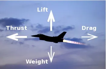
- Take – Off Power -
Take off power is the phase of flight in which an aerospace vehicle leaves the ground and becomes airborne.
For the aircraft that take off horizontally, this usually involves starting with a transition from moving along the ground on a runway.
The take-off speed requires varies with air density, aircraft gross weight, & aircraft configuration.
The power from the engine of the aircraft used to achieve the flight is called take off power & for light aircraft usually full power is required during take-off, large transport category (airliner) may use reduced power for take-off, where less than full power is applied in order to prolong engine life, reduce maintaining cost, and reduce noise emissions.
This term is also known as take-off thrust. Pilots use great amount of thrust at take – off to decrease engine wear at take-off. Reduced power are dreaded take-off are normal & frequently used.
The performance is carefully calculated prior to each take-off ensuring proper speed, power setting and flaps are used for weight of the take-off on the runway intended & at the proper temperature. When using this method of take-off, it is always possible to increase to full power if the situation requires.
- Aircraft Tyre (Design & Construction) –
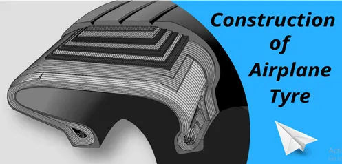
When it comes to safety, Tyres are one of the most important components of the aircraft. They help to absorb the shock of landing & provide cushioning. It also provides the necessary traction for braking & stopping of an aircraft.
An aircraft is designed to withstand extremely heavy loads while landing, take-off, taxing & parking. The no. of wheels required for aircraft increases with the weight of the aircraft, as the weight of the aeroplane needs to be distributed more evenly.
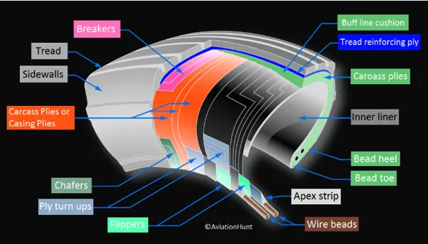
The aircraft tyre is specifically designed because the tyre has to withstand more load & also higher speed at the same time. The number of tyres required for aircraft increases with aircraft’s weight, as the weight of the aircraft needs to be distributed more evenly. Aircraft’s tread pattern is designed to facilitate stability in high crosswind conditions, to channel water away to prevent hydroplaning and for braking effect. Some of the typically used tyre designs are –
Bias – ply tyres –
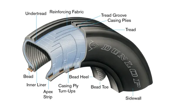
The Bias ply tyre consists of casing piles running diagonally at approximate right angles to one another.
The number of piles and the angles at which they are laid dictate strength and load capacity.
High performance Bias Aircraft tyre features inter-trade reinforcing fabric (ITF), thus provides additional high-speed stability. Reduces tread distortion under load, protects the casing piles from damage and can act as wear indicators on retreadable tyres.
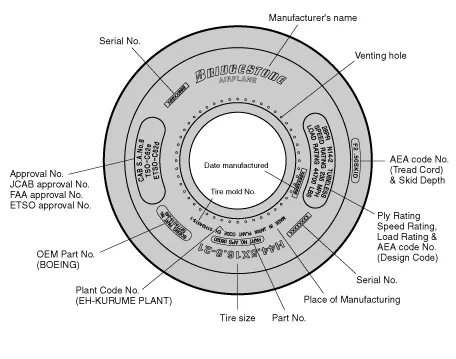
Tyre Terminology –
- Apex Strip – A triangular strip of stiff rubber which is fitted on to the bead core to taper the rigid bead into the flexible body piles in the sidewall.
- Bead heel – Outer edge of the bead.
- Bead toe – Inner edge of the bead.
- Breaker – Breakers are fabric piles placed directly on to the most upper ply beneath the tread rubber. They disperse tread throughout the tire. These breakers are utilized in a limited number of any company’s aircraft tyres.
- Chafer strip – Reinforces the beads and protects the cord body piles from damage from rim friction or from damage while replacing the rims.
- Carcass plies – Each nylon ply is held by wire beads across the tyre to keep the tensile strength at the proper level & it’s folded to the side of the sidewall. Each ply is provided with cushion rubber to reduce the shearing force produced between the cords of the tyre when it is deformed. Multiple coated nylon cords are crossed alternately on the bias to make the carcass.
- Decoration Line – A projecting embossed line moulded between the shoulder and the sidewall of a tyre. Its purpose id for decoration only.
- Flipper strip – A strip of material which is wrapped around the bead bundle & filler to add support & help tapper assembly into the sidewall.
- Inner Liner – A sheet of special rubber laminated to the inside of the first casing ply of tubeless tyre so as to ensure retention of pressure when the tyre is inflated.
- Ply turn–ups – The turned up ends of plies around the beads. Other plies lock the ends into place.
- Tread Reinforcing Fabric – Nylon cord plies are located in the tread between the tread grooves & outer ply of the carcass which reduces tread squirm & increase the stability for high speed operations.
- Rim line - The line is provided near the beads to allow inspection of tyre fitting with the rim.
- Shoulder – The area on the side of the tyre between the sidewall & the tread.
- Sidewall – The side area of the tire located between the buttress and the beads. Composed of rubber, it protects the carcass from damage.
- Tread – A layer of rubber on the outer circumference of the tyre, its major functions are to protect the casing from the cuts, withstand high speed during take-off & landing, provide traction, resist wear, provide durability during wide range of temperatures & to ensure stability (effective discharge of water in wet runways). The tread compound is designed to suit a wide range of operations.
- Under Tread - A rubber layer provided for use in retreading the tyre which provides adhesion of treads to the cord body. Tyre manufacturing Companies make this rubber layer thick enough to ensure high number of retreads.
- Wire Beads – constructed of steel wire encased in rubber, they help to maintain in shape of the tyre & keep securely fixed to the rim. The wire beads are wrapped with fabric.
- Venting hole – The hole through which gas is filled from inside the carcass plies.
- Balance Marker – The Balance Marker consists of red dot, affixed on the sidewall of the tyre immediately above the bead to indicate the lightweight point of the tyre.
Radial Tyre –
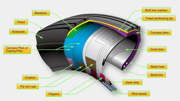
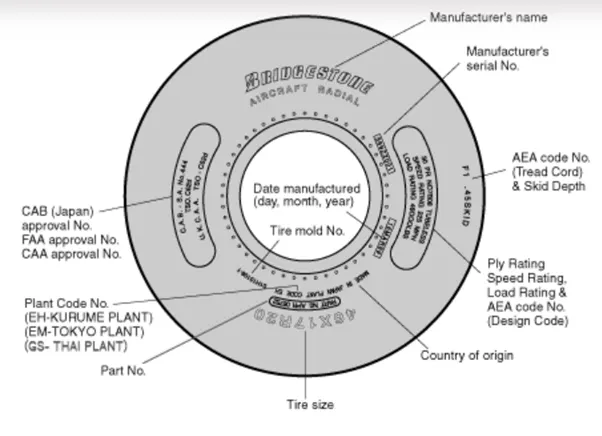
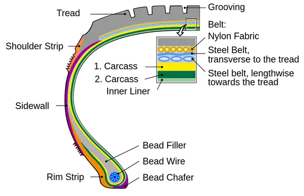
Radial tyres are modern designed aircraft tyres & its design is similar to that of aircraft tyres. Typically, the radial tyre offers more landings per trade & lighter weight than the bias tyres, though sometimes at the expense of retread lives. Radial aircraft tyres differs from Bias aircraft tyres in the plies that all run radially from bead to bead approximately at 90 degrees to the centre line of the tyre. Angled belt plies are made between the tread and top casing plies, resulting in a flatter tread & adding strength to the tyre.
Tyre Terminology –
Apex Strip – A triangular piece of stripper rubber which is fitted on to the bead core to taper the rigid bead into the flexible body plies in the sidewall.
- Aramid Cord protector – The tyre is constructed with an Armid ply insert between the tread and the top belt to prevent the damage to the tyre belts.
- Bead Heel – Outer edge of the Beed.
- Bead toe – Inner edge of the Bead.
- Inner Liner – A sheet of special rubber laminated to the inside of the first casing ply of tubeless tyre so as to ensure retention of pressure when the tyre is inflated.
- Ply turn–ups – The turned up ends of plies around the beads. Other plies lock the ends into place.
- Venting hole – The hole through which gas is filled from inside the carcass plies.
- Under Tread - A rubber layer provided for use in retreading the tyre which provides adhesion of treads to the cord body. Tyre manufacturing Companies make this rubber layer thick enough to ensure high number of retreads.
- Wire Beads – constructed of steel wire encased in rubber, they help to maintain in shape of the tyre & keep securely fixed to the rim. The wire beads are wrapped with fabric.
- Sidewall – The side area of the tire located between the buttress and the beads. Composed of rubber, it protects the carcass from damage.
- Tread – A layer of rubber on the outer circumference of the tyre, its major functions are to protect the casing from the cuts, withstand high speed during take-off & landing, provide traction, resist wear, provide durability during wide range of temperatures & to ensure stability (effective discharge of water in wet runways). The tread compound is designed to suit a wide range of operations.
- Rim line - The line is provided near the beads to allow inspection of tyre fitting with the rim.
- Chafer strip – Reinforces the beads and protects the cord body piles from damage from rim friction or from damage while replacing the rims.
- Belt Plies – Angled Belt plies which serves to add strength to the tyre especially in bead area.
- Chafer Strip – Protective layer of rubber & fabric which prevents chafing between cord body plies & the wheel.
- Balance Marker – The Balance Marker consists of red dot, affixed on the sidewall of the tyre immediately above the bead to indicate the lightweight point of the tyre.
- Rolling Resistance –
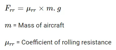
Rolling resistance is the force resisting the motion when a body (such as ball, tyre or wheel) rolls on a surface.
Rolling resistance can be seen in the aircraft when the aircraft takes-off from the runway & while landing at the runway with the help of their wheels.
The Rolling resistance can be expressed as –
- Tyre Pressure –
Aircraft tyres are generally operated at high pressures up to 200 Psi (16 Bar, 1400 Kpa) for airliners and even higher for business jets.
The main landing gear on the Concorde was typically inflated to 232 Psi whilst the tail bumper gear tyres were as high as 294 Psi (20.3 Bar). The high pressure and the weight load on the Concorde tyres were a significant factor in the loss of the Air France Flight 4590.
Tests of airliner aircrafts tyres have shown that they are able to sustain pressures of maximum 800 Psi (55 Bar, 5500 Kpa) before bursting. During the testing the tyres have to be filled with water in order to prevent the test room being blown apart by the energy that would release by the gas when the tyre bursts.
Aircraft tyres are usually inflated with nitrogen to minimise expansion & contraction from the extreme changes in ambient temperature & pressure experienced during flight. Dry nitrogen expands at the same rate as dry atmospheric gases (Normal air has about 80% Nitrogen), but common compressed air sources may contain moisture which increases the expansion rate with temperature.
The requirement that an inert gas, such as nitrogen be used instead of air for inflation of tyres for certain transport category airplanes are prompted by atleast 3 cases in which the oxygen in air filled tyres combined with volatile gases given off by severely overheated tyre and exploded upon reaching auto ignition temperature the use of an inert gas for tyre inflation will eliminate the possibility of a tyre explosion.
- Brake Forces while Landing –
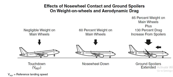
Aircraft brakes stop moving aircraft by converting its Kinetic Energy to heat energy by means of friction between rotating & stationary discs located in brake assemblies in the wheels. Brakes provide this critical stopping function during landings to enable airplanes to stop within the length of the runway.
Following braking devices are used to decelerate the aircraft –
- Ground Spoilers.
- Wheel Brakes (Including Anti-Skid systems & Auto-Brake systems).
- Thrust Reverser.
Ground Spoilers –
Ground spoilers usually deploy automatically (if armed) upon main-landing-gear-touchdown or upon activation of thrust reversers.
Ground spoilers provide 2 aerodynamic effects –
- Increased aerodynamic drag which contributes to aircraft deceleration.
- Lift-Dumping which increases the load on the wheels and thus increases the wheel braking efficiency.
Wheel Brakes -
Braking action results from friction force between the tyres & the runway surface.
The friction force is affected by –
Wheel speed (i.e. Free rolling, skidding or rocked);
Tyre condition & pressure (i.e. friction surface);
Runway Condition (i.e. Runway friction coefficient);
The load applied on the wheel.
Braking force is equal to the load applied on the wheel multiplied by the runway friction coefficient.
Anti-skid systems are designed to maintain the wheel-skidding factor (also called the slip ratio) near the point providing the maximum friction force, which is approximately 10% on a scale from 0% to 100% locked wheel).
Autobrake systems are designed to provide a selectable declaration rate, typically between three knots/sec. to six knots/sec.
When a low autobrake deceleration rate is selected & the brake pressure is applied usually after specific time delay to give priority to the thrust reverser deceleration force at high airspeed.
Thrust Reversers –
Thrust reversers provide a deceleration force that is independent of runway condition. Thrust reverser efficiency is higher at high airspeed therefore, thrust reversers must be selected as early as possible after touchdown (in accordance with standard operating procedures).
Thrust reversers should be returned after reverse idle at low airspeed (to prevent engine stall or foreign object damage) & stowed a taxi speed. Nevertheless, maximum engine speed can be maintained to a complete stop in an emergency.
- With necessary assumptions calculate the force & power required to push / pull an aircraft by towing a vehicle.
Let’s assume
Weight of the Aircraft (Airbus A-380) = 575000 kg.
Rolling Resistance Coefficient of an Airbus (rr) = 0.004.
Weight of the towing tractor = 50000 Kg.
Rolling Resistance coefficient of the towing tractor (rr) = 0.001
Rolling Resistance force of the towing tractor = rr * m.g = 0.001*50000*9.81 = 0.49 KN.
Rolling Resistance force of an Aircraft = rr * m.g = 0.004*575000*9.81 = 22.56 KN.
Total Rolling Resistance Force = Rolling Resistance force of an Aircraft + Rolling Resistance force of the towing tractor
= 0.49 + 22.56
= 23.05 KN.
Air-Drag Force –
It is the force which occurs due to the Air Strike effect on the wheel when it moves. The vehicle moves through the air medium of particular density value with certain speed this causes the air strike against the vehicle body & it causes Drag force on the vehicle.
The Aerodynamic Drag is given by the following equation –
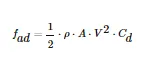
`rho`= Density of the air medium.
A = Frontal area of the vehicle which strikes the vehicle.
V = Velocity with which the vehicle moves.
Cd = Coefficient of Drag which varies different shapes of the frontal area.
Let’s assume
The Velocity of the Aircraft while Towing = 30 Kmph. (8.33 m/s)
Density of Air medium (`rho`) = 1.225.
The frontal area of the Aircraft = 20 m2.
The coefficient of the Drag of the Aircraft = 0.026.
Air Drag Force = 0.5*`rho`*A*V2* Cd = 0.022 KN.
Air Drag Force of the Aircraft = 0.022 KN.
Therefore,
The Total Force that the motor needs to overcome = Total Rolling Resistance Force of an Aircraft + Drag force acting on the Aircraft.
Hence, the Total Force acting = 23.05 + 0.0022
The Total Force that the motor needs to overcome in order to push or pull the Aircraft = 23.07 KN.
The Power required –
The power required by the motor is given by the velocity with which the towing operation takes place.
The average speed of Push/Pull = 20Kmph.
Power required by the motor = Total Force * Velocity = 23.07 * 5.5 = 126.8 KW.
Power required by the motor= 126.8 KW.
The torque output of the Towing Tractor can also be calculated by following steps –
Fte = The Total Tractive Force 9Rolling Resistance Force + Air Drag Force.
T = Torque Output.
r = Radius of Tyre.
G = Gear Ratio.
For heavy duty Towing Tractor, we assume –
G = 11 (for delivering high torque)
r = Radius of Tyre = 25 inches = 0.635 m.
The Torque required to Push or Pull for above stated condition = 1.327KNm.
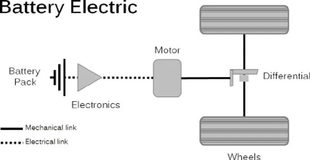
- Design an electric powertrain with a type of motor, its power rating & energy requirement to fulfil aircraft towing application, estimate the duty cycle range to control the aircraft speed from 0 to highest. Make all required assumed parameters. Draw a block diagram of powertrain.
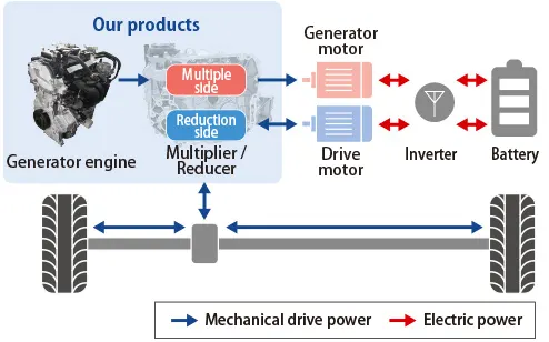
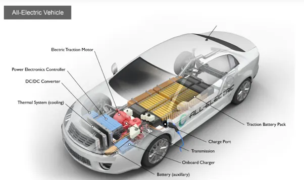
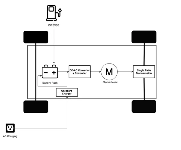
An EV powertrain has 60% less components than the powertrain of an ICE vehicle. These components are described below –
Battery Pack –
The Battery pack is made up of multiple lithium ion cells & stores the energy needed to run the vehicle. Battery pack provides the Direct current (DC) output.
DC-AC Converter –
The DC supplied by the battery pack is converted to AC & supplied to an electric motor. This power transfer is managed by sophisticated motor control mechanism (Referred as Powertrain Control Electronic Unit) that control the frequency & magnitude of voltage supplied to the electric motor in order to manage the speed & acceleration as per driver’s instructions communicated via acceleration/brakes.
Electric Motor –
Converts electrical energy to mechanical energy which is delivered to the wheels via single ratio transmission. Many EVs use motor generators that can perform regeneration as well.
On-Board Charger –
Converts AC received through charge port to DC & controls the amount of current flowing into the battery pack.
Core components of EV powertrain –
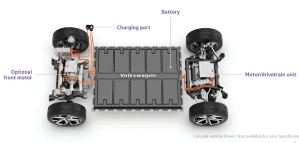
Motor Design -
Type of Motor = BLDC motor.
Rated Power = 20-25 KW.
Peak Power = 50 KW.
Speed = 3200-5000 RPM.
Rated Torque = 80 Nm.
Peak Torque = 160 Nm.
Efficiency = > 80%.
In Power Rating –
The Rated Power of the motor is 25KW & the Peak Power of the motor is double the rated power of the motor which is 50KW.
The converter used in this is DC-AC converter.
Assuming the input voltage = 349 V.
Input Current = 70 A.
Now, Power Input = Voltage * Current = 349 * 70 = 24.30 KW.
Energy requirements –
The energy requirement for an EV is similar to the Towing vehicle to push/pull the aircraft is calculated on the basis of time.
Let, Energy = Power * Time taken by towing the vehicle to push/pull the aircraft.
We know that the power = 24.30 KW.
Time taken by the Towing Vehicle to push/pull the Aircraft = 15 Minutes.
So, energy = 24.30 * 15* 60 = 21870 KJ.
Therefore, power required by single Towing Vehicle is 6.075 KW.
Duty Cycle –
Duty Cycle of the Electric Powertrain is calculated as Output Power by the Input Power by this we get efficiency of the Duty Cycle.
So, here in this case –
Duty Cycle = Output Power/Input Power
We know that,
Output Power = 19.94 KW.
Input Power = 24.30 KW.
Therefore, the Duty Cycle = 19.94/24.30
= 0.82%
Therefore, the efficiency of the Duty Cycle we get for this Electric Powertrain is 0 to 0.82%