Project-1: Powertrain for aircraft in runways
Pratik Mankar
Part A
AIM
- Search and list out the total weight of various types of aircrafts.
- Is there any difference between ground speed and air speed?
- Why is it not recommended to use aircraft engine power to move it on the ground at Airport?
- How an aircraft is pushed to runway when its ready to take off?
- Learn about take off power, tyre design, rolling resistance, tyre pressure, brake forces when landing.
1] Search and list out the total weight of various types of aircrafts.
The weight of the aircraft is needed to be calculated by the pilot for every flight to ensure the aircraft remains within weight limitations set by the manufacturer. These limitations are to ensure the aircraft is able to perform and recover from all flight maneuvers and withstand structural loading.
In an aircraft, the centre of gravity (CG) is the point about which the aircraft would balance when it is suspend by that point. As the location of the centre of gravity affects the stability of the aircraft, it must fall within specified limits that are established by the aircraft manufacturer. Both lateral and longitudinal balance are important, but the primary concern is longitudinal balance; that is, the location of the CG along the longitudinal or lengthwise axis.
From “Manufacturing” to “Commissioning” and from “On the Ramp” to “Take-off” there are huge variations in the weight and balance of an aircraft. It varies significantly, so striking a correct balance with all loads on an aircraft is significantly important.
Prerequisites:
- Weight of a male person – 88 kg (avg)
- Weight of a female person – 70 kg (avg)
- Weight of children (2-12) years – 35 kg (avg)
- Weight of cabin crew – 75 kg (including 3kg of crew baggage) (avg)
- Weight of fuel in aircraft can be approximated as approx 12000 kgs for 4000 km by an narrow body aircraft (A-320).
- Payload – Passengers, Cargo, Mail, Baggage. (mainly)
1) Manufacturer’s Empty Weight (MEW): It is the weight of the aircraft “as built” and includes the weight of the structure, power plant (engines), furnishings, installations, systems and other equipment that are considered an integral part of an aircraft.
2) Zero Fuel Weight (ZFW): This is the total weight of the airplane and all its contents including unusable fuel (unusable fuel is the fuel which is required to maintain the structural stability of the aircraft, especially wings), but excluding the total weight of the usable fuel on board (usable fuel is the fuel necessary for the flight). Note: As a flight progresses and fuel is consumed, the total weight of the airplane reduces, but the ZFW remains constant.
3) Operational Empty Weight (OEM) or Dry Operating Weight (DOW): It is the basic weight of an aircraft including the crew, all fluids necessary for operation, (such as engine oil, engine coolant, water, unusable fuel) all operator items and equipment required for flight but excluding usable fuel and the payload.
4) Maximum Zero Fuel Weight (MZFW): Maximum zero fuel weight (MZFW) is the maximum weight allowed before usable fuel and other specified usable agents (engine injection fluid, and other consumable propulsion agents) are loaded. OR (OEM / DOW + Payload = MZFW).
5) Maximum Taxi Weight (MTW) or Maximum Ramp Weight (MRW): It is the maximum permitted weight of the aircraft at which it may be moved on the ground either with its own engine or towed by a tractor. It can also be defined as maximum weight for ground maneuvering including the weight of run-up and taxi fuel. (MZFE + Ramp Fuel = MRW).
6) Maximum Take-Off Weight (MTOW): It is the maximum permitted weight at the start of the take-off. While determining this limit, the manufacturer takes into consideration the strength of the material used for the manufacturing of the aircraft and standard performance variables such as runway temperature, altitude, atmospheric pressure, wind components, flaps, etc. (MZFW + Take-Off Fuel = MTOW).
7) Regulated Take-Off Weight (RTOW): As told in the above definition depending on different factors (e.g. flap setting, altitude, air temperature, length of runway), RTOW or maximum permissible takeoff weight varies for each takeoff. It can never be higher than MTOW.
8) All Up Weight (AUP): DOW + Payload + Fuel.
9) Maximum Landing Weight (MLW): When aircraft touches the ground it puts force of the runway as well as on the tyres and under carriage, so to ensure structural safety of the aircraft MLW is taken into consideration. Manufactures have calculate this force to be approximately “9” times the weight of the aircraft. Thus when the aircraft has to make an emergency landing or when the weight of the aircraft before landing exceeds the MLW defined by the manufacturer the pilots dump fuel to reduce the weight of the aircraft. (MTOW – Trip Fuel = MLW).
Weight- Takeoff Weight components Graph
Maximum ramp weight (MRW)
also called maximum taxi weight (MTW)
It is the maximum weight authorized for maneuvering (taxiing or towing) an aircraft on the ground.
Aircraft gross weight
It is the total aircraft weight at any moment during the flight or ground operation. This decreases during flight due to fuel and oil consumption.
To sum up and to get a more clear picture, have a look on the image below:
AS350 Astar B2 Helicopter Specs:
Aircraft Empty Weight: 3000 lbs
Aircraft Maximum Gross Weight: 4961 lbs
Aircraft Maximum Fuel Weight: 1000 lbs
Aircraft Useful Load: 1961 lbs
Scenario #1: All Fuel & No Cargo or Passengers
This would be on a flight when I have finished a job and I am returning back to the hanger after dropping off the passengers and their cargo:
Aircraft Empty Weight: 3000 lbs
Pilot Weight: 185 lbs
Aircraft Full Fuel Weight: 1000 lbs
Total Aircraft Weight = 4,185 lbs (776 lbs under MGTW).
Scenario #2: Full Passengers & 200 lbs of Cargo
This would be on a flight when I am starting a job in the morning and I am departing from the hanger with a work crew and their tools.
Aircraft Empty Weight: 3000 lbs
Pilot Weight: 185 lbs
Passengers Weight: 950 lbs
Cargo Weight: 200 lbs
Aircraft Full Fuel Weight: 1000 lbs
Total Aircraft Weight = 5,335 lbs (374 lbs OVER MGTW)
In this scenario I would need to offload weight. The 3 variables are,
- Passengers
- Cargo
- Fuel
Usually, the passengers and their cargo need to go as they are the ones doing the work, so fuel has to be reduced. Instead of filling the aircraft fuel tank up to 100%, I can only fill it to around 60% to keep the aircraft under its MGTW.
This just means that I may need to refuel more often or plan the day to have a fuel stop en route somewhere.
Typical Airplane Weights
Below is a table of some of the most common aircraft flying around our skies today:
| Aircraft | Empty Weight | Max Fuel Weight | Max Cargo Weight | Max Gross Takeoff Weight |
|---|---|---|---|---|
| Antanov AN-225 | 628,000 lbs 285,000 kg |
661,400 lbs 300,000 kg |
417,000 lbs 190,000 kg |
1,411,000 lbs 640,000 kg |
| Airbus A380-800 | 611,000 lbs 277,000 kg |
560,000 lbs 254,000 kg |
185,000 lbs 84,000 kg |
1,268,000 lbs 575,000 kg |
| Boeing 747-800 | 485,300 lbs 220,100 kg |
427,400 lbs 194,000 kg |
295,000 lbs 134,000 kg |
987,000 lbs 447,700 kg |
| Airbus A340-500 | 370,000 lbs 168,000 kg |
386,300 lbs 175,000 kg |
119,000 lbs 54,000 kg |
820,000 lbs 372,000 kg |
| Boeing 777-300ER | 370,000 lbs 168,000 kg | 320,800 lbs 145,500 kg | 148,000 lbs 67,100 kg |
776,000 lbs 352,000 kg |
| Boeing 787-10 | 299,000 lbs 135,500 kg | 223,500 lbs 101,500 kg |
126,300 lbs 57,300 kg | 560,000 lbs 254,000 kg |
| Boeing 737-900 | 98,500 lbs 44,700 kg |
53,100 lbs 24,000 kg |
44,600 lbs 20,200 kg |
187,000 lbs 85,000 kg |
| Airbus A320-100 | 93,900 lbs 42,600 kg |
48,700 lbs 22,100 kg |
44,000 lbs 20,000 kg |
150,000 lbs 68,000 kg |
| Embraer 190 | 63,500 lbs 28,800 kg |
28,600 lbs 13,000 kg |
28,800 lbs 13,100 kg |
106,000 lbs 48,000 kg |
| Gulfstream G650 | 54,000 lbs 24,500 kg | 48,200 lbs 21,900 kg | 6,500 lbs 3,000 kg |
100,000 lbs 45,200 kg |
| Bombardier CRJ900 | 48,160 lbs 21,850 kg | 19,600 lbs 8,900 kg | 6,075 lbs 2,760 kg | 80,500 lbs 36,500 kg |
| Bombardier Q400 | 39,300 lbs 17,800 kg |
11,700 lbs 5,300 kg |
18,700 lbs 8,500 kg |
62,000 lbs 28,000 kg |
| Learjet 75 | 13,900 lbs 6,300 kg | 6,060 lbs 2,750 kg |
2,900 lbs 1,300 kg |
21,500 lbs 9,700 kg |
| Cessna Citation CJ4 | 10,300 lbs 4,700 kg | 5,800 lbs 2,650 kg |
2,200 lbs 1,000 kg | 17,200 lbs 7,800 kg |
| Beechcraft King Air B100 | 7,100 lbs 3,200 kg | 3,200 lbs 1,450 kg |
4,150 lbs 1,900 kg |
12,000 lbs 5,400 kg |
| Diamond DA50 RG | 3,200 lbs 1,450 kg |
340 lbs 155 lbs |
1,250 lbs 560 kg |
4,400 lbs 2,000 kg |
| Beechcraft Bonanza G36 | 2,500 lbs 1,150 kg | 450 lbs 200 kg |
850 lbs 385 kg |
3,660 lbs 1,660 kg |
| Cessna 206H | 2,200 lbs 990 kg |
520 lbs 235 kg |
1,150 lbs 520 kg |
3,600 lbs 1,630 kg |
| Sirrus SR22 | 2,250 lbs 1,000 kg | 485 lbs 220 kg |
950 lbs 430 kg |
3,600 lbs 1,630 kg |
| Cessna 172R | 1,700 lbs 770 kg |
380 lbs 170 kg |
560 lbs 255 kg |
2,425 lbs 1,100 kg |
2] Is there any difference between ground speed and air speed?
While ground speed is the airplane’s speed relative to the surface of the Earth, airspeed – at least true airspeed – is its speed relative to the air it is flying in.
Ground Speed
Ground speed is the horizontal speed of an aircraft relative to the Earth’s surface.[1] It is vital for accurate navigation that the pilot has an estimate of the ground speed that will be achieved during each leg of a flight. An aircraft diving vertically would have a ground speed of zero. Information displayed to passengers through the entertainment system of airline aircraft usually gives the aircraft ground speed rather than airspeed. Ground speed can be determined by the vector sum of the aircraft's true airspeed and the current wind speed and direction; a headwind subtracts from the ground speed, while a tailwind adds to it. Winds at other angles to the heading will have components of either headwind or tailwind as well as a crosswind component.
An airspeed indicator indicates the aircraft's speed relative to the air mass. The air mass may be moving over the ground due to wind, and therefore some additional means to provide position over the ground is required. This might be through navigation using landmarks, radio aided position location, inertial navigation system, or GPS. When more advanced technology is unavailable, an E6B flight computer may be used to calculate ground speed. Ground speed radar can measure it directly. Ground speed is quite different from airspeed. When an aircraft is airborne the ground speed does not determine when the aircraft will stall, and it doesn't influence the aircraft performance such as rate of climb.
Wind Speed
For a reference point picked on the ground, the air moves relative to the reference point at the wind speed. A positive velocity is defined to be in the direction of the aircraft's motion. We are neglecting cross winds, which occur perpendicular to the flight path but parallel to the ground, and updrafts and downdrafts, which occur perpendicular to the ground.
Airspeed
The important quantity in the generation of lift is the relative velocity between the object and the air, which is called the airspeed. Airspeed cannot be directly measured from a ground position, but must be computed from the ground speed and the wind speed. Airspeed is the vector difference between the ground speed and the wind speed.
Airspeed vs. Ground Speed
As mentioned above, true airspeed is simply the speed at which an aircraft is moving relative to the air it is flying in. As such, it’s also the speed at which the air is flowing around the aircraft’s wings.
Ground speed, on the other hand, is the aircraft’s speed relative to the ground. One thing that should be noted here is that it’s its horizontal rather than vertical speed – an aircraft climbing completely vertically would have a ground speed of zero.
In other words, while airspeed is what determines whether there is enough airflow around an aircraft to make it fly, ground speed is what determines how fast an aircraft will get to its destination.
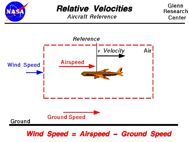
Wind’s Effect on Ground Speed
The relationship between airspeed and ground speed is fairly simple. Ground speed is simply the sum of airspeed and wind speed.
If the aircraft is flying in the same direction as the wind is blowing, the aircraft experiences tailwind, and its ground speed is higher than its airspeed. On the other hand, if the wind is blowing against the direction the aircraft is traveling in, the aircraft experiences headwind, and its ground speed is lower than its airspeed.
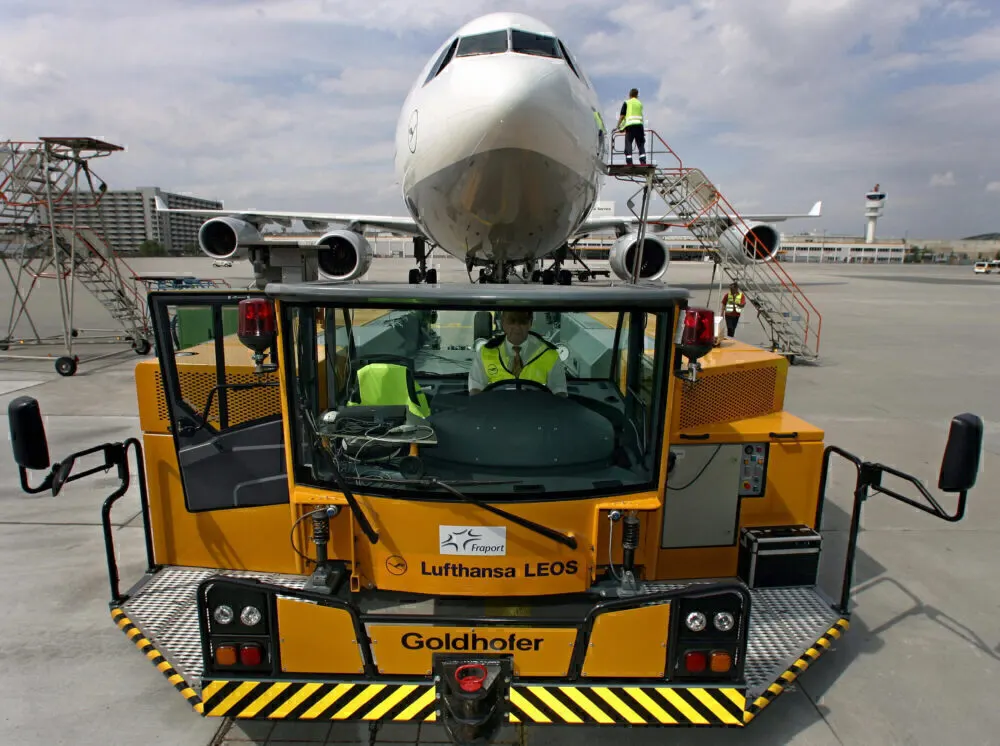
Reasons for not using aircraft engine power to move it on the ground at Airport:-
- Usage of high power mounted engines have high risk of blasting.
- Usage of low power mounted engines have a risk of impurities on the ground may enter inside the engine.
- High fuel cost since areoplanes uses large amount of power
- It also saves fuel virgin Atlantic hadproposed a new system in which pushback truck will move the aircraft all the way to runway to save fuel and reduce impact of environment.
- The plane engines are very loud. When more than one plane will add up their sound, than it will not be pleasent for passangers and others near airport.
4] How an aircraft is pushed to runway when its ready to take off?
Airplanes have engines, and they can use them to move forward along the ground. So they push themselves to the runway. It is true that most of the time, a small vehicle is needed to push the larger commercial airplanes backwards away from the terminal building, because even if a plane can reverse it’s thrust, it’s not always safe to hit the buildings with that reverse thrust. So the little trucks push the bigger planes back away from the buildings, but after that, the planes can apply a small amount of engine power to roll forward just as all airplanes can.
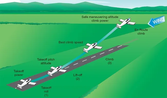
Takeoff is that part of flight during which the associate region vehicle leaves the bottom and becomes mobile. For craft traveling vertically, this is often referred to as rising. For a plane that starts up horizontally, this typically involves beginning with a transition from moving on the bottom on a runway. For balloons, helicopters, and a few specialized fixed-wing planes (VTOL craft like the Harrier), no runway is required.
Ready for take-off in ten steps
- The pilot parks the aircraft in exactly the right place. Usually with the help of an automatic system, but occasionally guided by a marshaller waving two paddles or wands. Dozens of handling personnel are already standing by to perform a whole range of tasks simultaneously.
- As soon as the aircraft is stationary and the engines are switched off, the first priority is to disembark the passengers as quickly as possible. The apron handler places chocks in front of the wheels and connects the ground power. Meanwhile, the passenger bridge manoeuvres up to the door and a belt loader rolls up to the cargo hold. Luggage is unloaded and transferred to the terminal on baggage carts.
- Refuelling begins, usually from a hydrant at the stand. A hose is attached to this from a special vehicle called a dispenser, with the other side connected to the fuel tank in the wing. Read more about refuelling here.
- Now it is time to service the aircraft. The caterer loads new meals and takes away the food waste and used cutlery and crockery. Other activities include draining the lavatories, replacing the headrest covers, removing rubbish and distributing fresh blankets and in-flight magazine.
- A specialist team – or sometimes the crew themselves – cleans the cabin so that the new passengers board a pristine aircraft.
- Meanwhile, specialists from the airline conduct a technical check to make sure that the engines, wings, control surfaces, landing gear, instruments, doors and other equipment are in full working order.
- The aircraft is now ready for baggage to be loaded for the next flight. This is a quick process, on average taking only 10-15 minutes. A little later the passengers start boarding. As soon as they are all in their seats, the door is closed and the pilot informs air-traffic control that the flight is ready for departure.
- The apron handler removes the chocks. A so-called pushback truck reverses the aircraft into taxiing position, pushing it with a towbar attached to the nose-wheel strut. Or, in the most modern versions, by actually lifting the wheel. That speeds up coupling and decoupling.
- The aircraft taxis to the runway to depart at the agreed time.
- The pilot waits for permission to take off from air-traffic control. This is possible once the departure route is clear. As soon as the go-ahead is received, the plane takes to the air at full power.
5] Learn about take off power, tyre design, rolling resistance, tyre pressure, brake forces when landing.
1) Take Off Power
Power take-off (PTO) transfers the mechanical power of the engine over to another piece of the equipment. This allows for the power to move throughout the equipment to transmit energy even if it doesn’t have a motor or engine itself.
A power take-off or power takeoff (PTO) is one of several methods for taking power from a power source, such as a running engine, and transmitting it to an application such as an attached implement or separate machine.
Most commonly, it is a splined drive shaft installed on a tractor or truck allowing implements with mating fittings to be powered directly by the engine. Semi-permanently mounted power take-offs can also be found on industrial and marine engines. These applications typically use a drive shaft and bolted joint to transmit power to a secondary implement or accessory. In the case of a marine application, such shafts may be used to power fire pumps. In aircraft applications, such an accessory drive may be used in conjunction with a constant speed drive. Jet aircraft have four types of PTO units: internal gearbox, external gearbox, radial drive shaft, and bleed air, which are used to power engine accessories. In some cases, aircraft power take-off systems also provide for putting power into the engine during engine start. See also Coffman starter.
Also, in wave energy technology to harness the ocean wave energy, the power take-off systems are used. The working principle can vary and be classified as a direct mechanical drive system, hydro turbine transfer system, hydro motor system, pneumatic air turbine transfer system, and direct electrical drive system.
2) Tyre Design

The tyre-road contact area can hardly be taken for granted and it is not even similar from manufacturer to manufacturer. Each manufacturer has its own principles, engineering needs, care for detail, style and goals to be achieved. Precisely for this reason, each product has a precise, sophisticated and carefully designed pattern according to the intended use of the tyre and its construction materials. These elements make it possible to obtain the best efficiency in terms of safety and road efficiency with a focus on fuel consumption and running costs. The latter key aspect is held in the highest consideration by users of vehicles. The tread pattern distributed on the most crucial area of the tyre, which only slightly larger than the palm of an adult's hand, is fundamental for a number of reasons. These may be summarised also in terms of high driving quality and safety in tricky conditions.
Breaker tyre
Typical designation:
\r\n130/90 - 16 M/C 73H TL Reinforced
\r\n"}}">Typical designation:
130/90 - 16 M/C 73H TL Reinforced
Crossply tyre
Typical designation:
\r\n4.00 - 18 M/C 64H TL
\r\n"}}">On today's market the crossply tyre is the "classic" design. Its advantages are its simple structure and its sturdy sidewalls, which particuallary in off-road use offer many benefits (impact protection). Crossply tyres have a maximum design speed of 150 mph. Material used: usually rayon or nylon fabric.
Typical designation:
4.00 - 18 M/C 64H TL
Radial tyres feature a casing angle of approx. 90° to the circumferential direction (direction of travel) and a belt angle of 0 - 25° approximately. The belt, located under the tread area, gives the tyre stability and permits far higher speeds, as the centrifugal force deformation is subsantially lower. Reduced material thickness in the sidewall section means the tyre heats up less and the high speed strenght is futher increased.
In terms of riding dynamics, modern motorcycles are geared to radial tyres. As an example: a 4.00 - 18 M/C 64H TT tyre "grows" by approximately 2 cm on average at a speed of 131 mph, whereas a comparable radial tyre only expands by a few millimeters. The radial tyre can be recognised by the R in the designation on the sidewall of the tyre.
Typical designation:
190/50 ZR 17 M/C (73W) TL
Most common causes of rolling resistance applied to a wheel in motion are
- tire deformation
- friction between tire and road surface
- wheel friction with surrounding air
- friction in the wheel hub and bearings
- road surface deformation
Formula
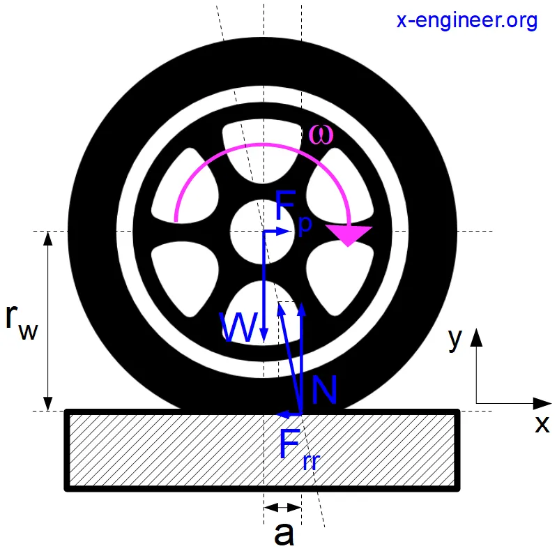
If the vehicle is rolling on a road with the gradient , then the formula for rolling resistance becomes
Frr = f · W · cos(α) = f · m · g · cos(α)
4) Tyre Pressure
Pressure is defined as a force exerted on a surface per unit area. To put it more simply, it’s the force that is put on a certain defined area. It’s likely you’ll be familiar with the concept in everyday life – for example ‘feeling the pressure’ or ‘applying pressure to a wound’, but when it comes to pressure and tyres, it can be difficult to understand the measurements of pressure, and know where to find them, which is why we’re going to take you through it. There are three commonly used measurements of pressure in tyres – PSI, BAR and kPa, and depending on your vehicle, you may need to convert from one to another. Tyre inflation pressure depends on the amount of air that has been pumped into your tyre. It is measured in pounds per square inch (psi), bar or kPa. Your vehicle manufacturer recommends the suitable pressure for your tyres.
Link Tyer Pressur
https://www.cars24.com/blog/car-tyre-air-pressure-size/
5) Brake forces when landing
Airplanes rely on a braking system to safely land on runways. At cruising altitude, most commercial airplanes fly at a speed of roughly 500 to 600 mph. When landing, however, they must reduce their speed. A typical 747, for instance, has a landing speed of about 160 to 170 mph. And upon touching the runway, airplanes must quickly brake until they come to a complete stop.
1) Wing Spoilers
Many airplanes use wing spoilers to assist with braking when landing. Not to be confused with ailerons, spoilers are extendable flaps on the ends of an airplane’s wings. Pilots can raise the spoilers to decelerate the airplane as it approaches the runway. And even while on the runway, pilots will typically leave the wing spoilers raised. Raised wing spoilers create drag, which essentially slows down the airplane so that it’s able to brake more quickly.
2) Disc Brakes
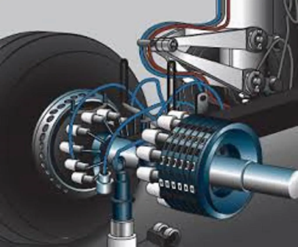
In addition to wing spoilers, airplanes use disc brakes. Airplane disc brakes are similar to the braking system in automobiles. They consist of a pair of calipers that, when engaged, squeeze pads against the rotors of an airplane’s landing gear.
Disc brakes are designed to remain static at all times. In other words, they don’t rotate with the wheels of an airplane’s landing gear. As the wheels turn, the disc brakes will remain static and stationary. They are a vital component of an airplane’s braking system because they are designed to apply pressure to the airplane’s wheels. Disc brakes will squeeze the wheels, thereby slowing down the speed at which they spin. In turn, this reduces the speed of the airplane so that it can come to a complete stop on the runway.
Brake Part
Types and Construction of Aircraft.
3) Reverse Thrust
Finally, many jet airplanes use reverse thrust to assist with braking during landings. Reverse thrust is a feature in jet engine airplanes that, as the name suggests, involves the reversal of the engines’ thrust. When flying, the thrust is projected out the rear of an airplane’s engines. When landing, however, pilots may use the reverse thrust feature. Reverse thrust changes the direction of the engines’ thrust. Rather than projecting out the rear, the thrust will be projected out the front. This reversal of thrust provides deceler
PART B
AIM
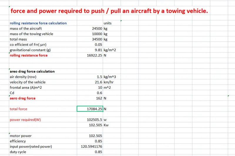
A. With necessary assumptions, calculate the force and power required to push / pull an aircraft by a towing vehicle.
B. Develop the model for the calculated force and power using Simulink.
A. Design an electric powertrain with type of motor, it’s power rating, and energy requirement to fulfill aircraft towing application in Simulink. Estimate the duty cycle range to control the aircraft speed from zero to highest. Make all required assumptions. Prepare a table of assumed parameters. Draw a block diagram of powertrain.
B. Also, Design the parameters in excel sheet
6]
A. With necessary assumptions, calculate the force and power required to push / pull an aircraft by a towing vehicle.
1)Rolling resistance force
As we have discussed in part-A 5c. It is the force resisting the motion when a body (such as a ball, tire, or wheel) rolls on a surface. Its governing equation is given as
The force to move an airplane on an absolute flat runway with no wind at constant low speed is equal to the rolloing resistance between the plane and the tarmac.

F=  *m*g
*m*g
where,
= Rolling resistance coefficient
m= Mass of the body
g= acceleration due to gravity
*m*
2)Aerodynamic Drag Force
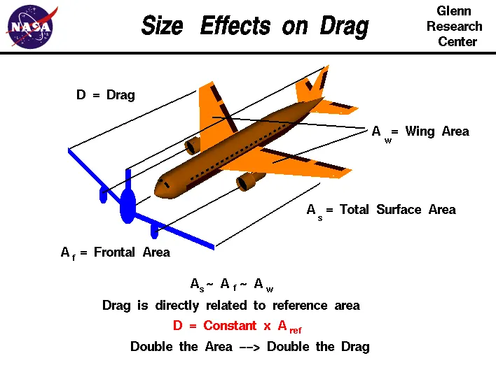
It is the force opposing the motion of the body. The drag coefficient is a common measure in automotive design as it pertains to aerodynamics. Drag is a force that acts parallel to and in the same direction as the airflow. The drag coefficient of an automobile measures the way the automobile passes through the surrounding air. When automobile companies design a new vehicle, they take into consideration the automobile drag coefficient in addition to the other performance characteristics. Aerodynamic drag increases with the square of speed; therefore, it becomes critically important at higher speeds. Reducing the drag coefficient in an automobile improves the performance of the vehicle as it pertains to speed and fuel efficiency. The governing equation of these force is given as following:

where,
 = drag force
 = mass density of the air
 = flow velocity relative to the object
 = drag coefficient
 = reference area
Calculation:-
let us assume that,
Mass of Towing Vehicle= 40,000kg
Mass of aircraft = 155,000kg
Total mass (m)= 40,000+155,000 =195,000kg
Frontal Area of the aircraft (A) =18 m2
Speed of the vehicle ( ) =25Kmph
converting it into m/sec
= 25*(1000/3600)=6.9445m/sec
Drag coefficient (Cd) =0.75
Air density ( ) =1.225Kg/m3
Calculating Rolling resistance Force (Frr) = *m*g
= 0.01*195,000*9.8
= 19,110N
Calculating Aerodynamic Drag Force (Fd)=0.5* * Cd*A* v^2
=0.5*1.225*18*0.75*(6.9445)2
=398.769N
Therefore the total Force required to push/pull the aircrcraft by the towing vehicle (F) = Frr+ Fd
= 19,110+ 398.769
= 19,508.769 N
Calculating the power (p) = Force*Velocity
= 19508.769* 6.9445
=135.478kW
B. Develop the model for the calculated force and power using Simulink.
Blocks Used
1)Constant
2)Sum
3)Product
4)Square
5)Display
Simulink Model
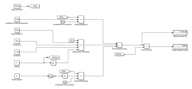
Explaination:-
In order to understand the above simulink model we do reverse engineering.
- For calculating power we have to multiply both total force(F) and velocity in m/sec for this we have used 'product' block (P=F*V).
- For calculating the Total Force(F) we have added both Frr & Fd by using 'Sum' block as shown in the above figure.
- To find the value of rolling resistance (Frr) we used product to multiply the values Crr, Total mass(m) & gravity (g) which are to be entered in the 'Constant' block.
- Similarly for calculating Drag force(Fd) we have to multiply the velocity in m/sec,Drag coefficient, Frontal area of aircraft(A) and a constant value 0.5 which are to be entered in 'constant' block.
- In order to convert velocity in Kmph to m/sec we have multiplied it with 5/18.
7]
A. Design an electric powertrain with type of motor, it’s power rating, and energy requirement to fulfill aircraft towing application in Simulink. Estimate the duty cycle range to control the aircraft speed from zero to highest. Make all required assumptions. Prepare a table of assumed parameters. Draw a block diagram of powertrain.
According to study 6 for towing an aircraft of 40000kg needed 39.24kW of power.
So we are selecting a motor which can take this much power.
Vehicle Drive: 58.3 HP/45.5 kW, 80 VDC Traction Motor mated with Auburn/Dana 44 Differential.
Aurburn is a high performance series differential which deliver more traction and faster engagement for controlled power transfer and lightning fast reaction to changing load.
Power Output= 45.5 kW
Batteries: Two 40 VDC Industrial, 595 AMP-HR Batteries (6 hr rate), wired in series.
Power Input= V* I
=80*595 = 47.6 kW
Efficiency of motor = Power Output / Power Input
= 45.5/47.6
= 95.58 %
Energy required for towing aircraft= Required Power * Time
Assume taxing time = 15min
Therefore Energy required = 39.24 * 0.25
= 9.81 kWh
Assume highest speed =25 kmph
Duty cycle = Average power/ Peak power
= 39.24/45.5
= 86 %
Parameters:
|
Sl.NO |
Parameters |
Values |
|
1 |
Weight of Aircraft |
40000 kg |
|
2 |
Rolling Coefficient of Aircraft |
0.02 |
|
3 |
Rolling Coefficient of Tractor |
0.9 |
|
4 |
Highest speed |
25 kmph |
|
5 |
Taxing time |
15min |
|
6 |
Battery Voltage |
40 V (2nos) |
|
7 |
Motor Power |
45.5 kW |
|
8 |
Terminal Voltage |
80 V |
To Draw a block diagram of powertrain.
Battery: It stores the energy needed to run the vehicle. It provides the direct current (DC) output.
Converter: DC-DC converter converts the DC current and supply to the motor.
Controller: Between converter and motor we use a controller. It is used to manage the power transfer. It controls the frequency and magnitude of voltage supplied to electric motor in order to manage the speed and acceleration.
Electric Motor: Converts electrical energy to mechanical energy and deliver it into wheels via a transmission. Many EVs use motor generators that can perform regeneration as well.
Differential: To give power to both wheels from motor a differential is used, which also helps in fast engagement in controlled power.
power train model designed in simulink :
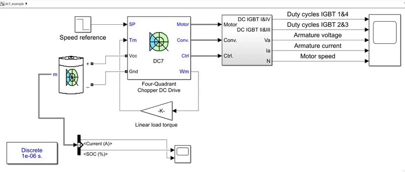
The below model represents the simple powertrain model for aircraft on the run way.
In general the power train consists of the battery (source), motor ,motor controller ,
This model consists of battery,four quadrant chopper dc drive (DC) The main purpose of the dc drive is it consists the controller also.
The dc 7 model is reference for the powertrain for the for aircraft on runway.
INPUT
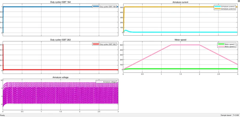
These are the plots for above powertrain :
The plot consists of the duty cycles of the contoller igbt swithes,
Armature voltage of the motor
armature current of motor
motor speed .and torque.
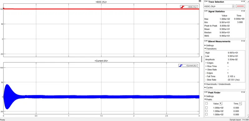
We used Li-ion battery connected to DC7 chopper with necessary parameter changes for towing, and we observed the output waveforms of Ia, V, Vdc, duty cycle of IGBT's, speed of motor.
OUTPUT
B. Also, Design the parameters in excel sheet.