Project-1: Powertrain for aircraft in runways
- To search and list out the various type of aircraft vehicle’s total weight
MTOW = Maximum take-off weight, MLW = Maximum landing weight, TOR = Take-off run (SL, ISA+15°, MTOW), LR = Landing run (SL, ISA+15°, MLW)
|
Type |
MTOW [kg] |
MLW [tons] |
TOR [m] |
LR [m] |
|
Antonov An-225 |
6,40,000 |
591.7 |
3500 |
|
|
Scaled Composites Model 351 Stratolaunch |
5,89,670 |
3660 |
||
|
Airbus A380-800 |
5,75,000 |
394 |
3100 |
1930 |
|
Boeing 747-8F |
4,47,700 |
346.091 |
3100 |
1800 |
|
Boeing 747-8 |
4,43,613 |
306.175 |
3100 |
|
|
Boeing 747-400ER |
4,12,770 |
295.742 |
3090 |
|
|
Antonov An-124-100M |
4,05,060 |
330 |
2520 |
900 |
|
Boeing 747-400 |
3,96,900 |
295.742 |
3018 |
2179 |
|
Lockheed C-5 Galaxy |
3,81,000 |
288.417 |
2530 |
1494 |
|
Boeing 747-200 |
3,77,840 |
285.7 |
3338 |
2109 |
|
Boeing 747-300 |
3,77,840 |
260.32 |
3222 |
1905 |
|
Airbus A340-500 |
3,71,950 |
240 |
3050 |
2010 |
|
Airbus A340-600 |
3,67,400 |
256 |
3100 |
2100 |
|
Boeing 777F |
3,47,800 |
260.816 |
2830 |
|
|
Boeing 777-300ER |
3,51,800 |
251.29 |
3100 |
|
|
Boeing 777-200LR |
3,47,450 |
223.168 |
3000 |
|
|
Boeing 747-100 |
3,40,200 |
265.3 |
||
|
Airbus A350-1000 |
3,08,000 |
233.5 |
||
|
Boeing 777-300 |
2,99,370 |
237.683 |
3380 |
|
|
Boeing 777-200ER |
2,97,550 |
213 |
3380 |
1550 |
|
Airbus A340-300 |
2,76,700 |
190 |
3000 |
1926 |
|
McDonnell Douglas MD-11 |
2,73,300 |
185 |
2990 |
1890 |
|
Airbus A350-900 |
2,70,000 |
175 |
2670 |
1860 |
|
Ilyushin Il-96M |
2,70,000 |
195.04 |
3115 |
2118 |
|
McDonnell Douglas DC-10 |
2,56,280 |
183 |
2990 |
1890 |
|
Boeing 787-9 |
2,54,000 |
192.777 |
2900 |
|
|
Boeing 787-10 |
2,54,000 |
201.849 |
||
|
Airbus A340-200 |
2,53,500 |
181 |
2990 |
|
|
Ilyushin IL-96-300 |
2,50,000 |
175 |
2600 |
1980 |
|
Airbus A330-300 |
2,42,000 |
185 |
2500 |
1750 |
|
Airbus A330-200 |
2,42,000 |
180 |
2220 |
1750 |
|
Lockheed L-1011-500 |
2,31,300 |
166.92 |
2636 |
|
|
Boeing 787-8 |
2,28,000 |
172.365 |
3300 |
1695 |
|
Lockheed L-1011-200 |
2,11,400 |
|||
|
Ilyushin IL-86 |
2,08,000 |
175 |
||
|
Boeing 767-400ER |
2,04,000 |
158.758 |
3414 |
|
|
Airbus A300-600R |
1,92,000 |
140 |
2385 |
1555 |
|
Boeing 767-300ER |
1,87,000 |
136.08 |
2713 |
1676 |
|
Concorde |
1,85,000 |
111.1 |
3440 |
2220 |
|
Airbus A300-600 |
1,63,000 |
138 |
2324 |
1536 |
|
Boeing 767-300 |
1,59,000 |
136.078 |
2713 |
1676 |
|
Airbus A310-300 |
1,57,000 |
124 |
2290 |
1490 |
|
Vickers VC10 |
1,52,000 |
151.9 |
||
|
Boeing 707-320B |
1,51,000 |
97.5 |
||
|
Boeing 707-320C |
1,51,000 |
112.1 |
||
|
Douglas DC-8-61 |
1,47,000 |
|||
|
Airbus A310-200 |
1,42,000 |
123 |
1860 |
1480 |
|
Airbus A400M |
1,41,000 |
122 |
980 |
770 |
|
Douglas DC-8-32 |
1,40,000 |
|||
|
Douglas DC-8-51 |
1,25,000 |
|||
|
Boeing 757-300 |
1,24,000 |
101.6 |
2550 |
1750 |
|
Boeing 707-120B |
1,17,000 |
86.3 |
||
|
Boeing 757-200 |
1,16,000 |
89.9 |
2347 |
1555 |
|
Boeing 720B |
1,06,000 |
79.5 |
||
|
Boeing 720 |
1,04,000 |
79.5 |
||
|
Tupolev Tu-154M |
1,04,000 |
80 |
||
|
Tupolev Tu-204SM |
1,04,000 |
87.5 |
2250 |
|
|
Convair 880 |
87,500 |
2.To find if there is any difference between ground peed and air speed.
One of the most confusing concepts for young scientists is the relative velocity between objects. Aerodynamic forces are generated by an object moving through a fluid (liquid or gas). A fixed object in a static fluid does not generate aerodynamic forces. Hot air balloons "lift" because of buoyancy forces and some aircraft like the Harrier use thrust to "lift" the vehicle, but these are not examples of aerodynamic lift. To generate lift, an object must move through the air, or air must move past the object. Aerodynamic lift depends on the square of the velocity between the object and the air. Now things get confusing because not only can the object be moved through the air, but the air itself can move. To properly define the relative velocity, it is necessary to pick a fixed reference point and measure velocities relative to the fixed point. In this slide, the reference point is fixed to the ground, but it could just as easily be fixed to the aircraft itself. It is important to understand the relationships of wind speed to ground speed and airspeed.
Wind Speed
For a reference point picked on the ground, the air moves relative to the reference point at the wind speed. Notice that the wind speed is a vector quantity and has both a magnitude and a direction. Direction is important. A 20 mph wind from the west is different from a 20 mph wind from the east. The wind has components in all three primary directions (north-south, east-west, and up-down). In this figure, we are considering only velocities along the aircraft's flight path. A positive velocity is defined to be in the direction of the aircraft's motion. We are neglecting cross winds, which occur perpendicular to the flight path but parallel to the ground, and updrafts and downdrafts, which occur perpendicular to the ground.
Ground Speed
For a reference point picked on the ground, the aircraft moves relative to the reference point at the ground speed. Ground speed is also a vector quantity so a comparison of the ground speed to the wind speed must be done according to rules for vector comparisons.
Airspeed
The important quantity in the generation of lift is the relative velocity between the object and the air, which is called the airspeed. Airspeed cannot be directly measured from a ground position, but must be computed from the ground speed and the wind speed. Airspeed is the vector difference between the ground speed and the wind speed.
Airspeed = Ground Speed - Wind Speed
On a perfectly still day, the airspeed is equal to the ground speed. But if the wind is blowing in the same direction that the aircraft is moving, the airspeed will be less than the ground speed.
Examples
Suppose we had an airplane that could take off on a windless day at 100 mph (liftoff airspeed is 100 mph). We are at an airport with an east-west runway that is 1 mile long. The wind is blowing 20 mph towards the west and the airplane takes off going east. The wind is blowing towards the aircraft which we call a headwind. Since we have defined a positive velocity to be in the direction of the aircraft's motion, a headwind is a negative velocity. While the plane is sitting still on the runway, it has a ground speed of 0 and an airspeed of 20 mph:
Airspeed = Ground Speed (0) - Wind Speed (-20) = 20 mph
The airplane starts its take off roll and has a constant acceleration a. From Newton's second law of motion, the ground speed V at any time t is:
V = a * t
and the distance d down the runway at any time is:
d = 1/2 * a * t^2
For a fixed length runway, this specifies the time to be used in the velocity equation. Let's assume that at 5000 feet down the runway, the velocity is 80 mph. Then the airspeed is given by
Airspeed = Ground Speed (80) - Wind Speed (-20) = 100 mph
and the airplane begins to fly. Now another pilot, with exactly the same airplane decides to take off to the west. The wind is now in the same direction as the motion and this is called a tailwind. The sign on the wind speed is now positive, not negative as with the headwind. The acceleration along the ground is the same, so at 5000 feet down the runway, the ground speed is again 80 mph. The airspeed is then given by:
Airspeed = Ground Speed (80) - Wind Speed (20) = 60 mph
This airplane doesn't have enough airspeed to fly. It runs off the end of the runway!
Significance of Understanding Relative Velocity
The importance of the relative velocity explains why airplanes take off and land on different runways on different days. Airplanes always try to take off and land into the wind. This requires a lower ground speed to become airborne, which means the plane can take off or land in the shortest distance traveled along the ground. Since runways have a fixed length, you want to get airborne as fast as possible on takeoff and stopped as soon as possible on landing. In the old days, a large "wind sock" was hung near the runway for pilots to see which way the wind was blowing to adjust their takeoff and landing directions. Now mechanical or electronic devices provide the information that is radioed to the cockpit.
The relationship between airspeed, wind speed, and ground speed explains why wind tunnel testing is possible and how kites fly.
In the wind tunnel, the ground speed is zero because the model is fixed to the walls of the tunnel. The airspeed is then the negative of the wind speed that is generated in the tunnel. Whether the object moves through the air, or the air moves over the object, the forces are the same.
A kite usually has no ground speed because a kite is held on the end of a string. But the kite still has an airspeed that is equal to the wind speed. You can fly a kite only with the wind at your back.
3.To find Why it is not recommended to use aircraft engine power to move it on the ground at airport.
When the engine is at full capacity the exhaust would be around 375mi/hr at this rate anything within the 200feet of the aircraft would blow away, get burnt, damage the hangars and anything that’s in the vicinity area, before every take off a maintenance check will be conducted, with the engine running at full capacity it is not possible.
There are quite a few reasons why aircraft engines are not used at the ground.
Efficiency:
At low power settings, combustion aircraft engines operate at lower efficiency than at cruise power settings. A typical A320 spends an average of 3.5 hours a day taxiing, using 600 liters (160 U.S. gal) of fuel. Hybrid electrically driven nose gear are under development to allow high use aircraft to shut down the engines during taxi operations.
FOD (Foreign Object Damage)
All aircraft may occasionally lose small parts during takeoff and landing. These parts remain on the runway and can cause damage to tires of other aircraft, hit the fuselage or windshield/canopy, or get sucked up into an engine. Although airport ground crews regularly clean up runways, the crash of Air France Flight 4590 demonstrated that accidents can still occur: in that case, the crash was said to have been caused by debris left by a flight that had departed only four minutes earlier.
On aircraft carriers, as well as military and some civilian airfields, sweeps are conducted before flight operations begin. A line of crewmen walk shoulder to shoulder along the flight operations surfaces, searching for and removing any foreign objects.
There have been numerous reports also that airport ground staff personnel has been sucked to the engine. Hence Due to efficiency cost and FOD its not recommended to use the aircraft engine instead pushback trucks are used
- To find how an aircraft pushed to its runways when its ready to take off.
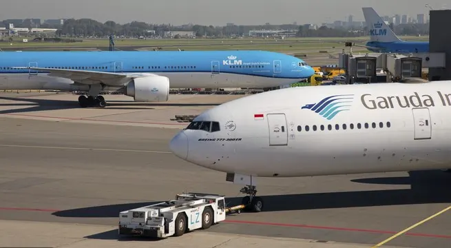
In aviation, pushback is an airport procedure during which an aircraft is pushed backwards away from an airport gate by external power. Pushbacks are carried out by special, low-profile vehicles called pushback tractors or tugs.
Pushbacks at busy aerodromes are usually subject to ground control clearance to facilitate ground movement on taxiways. Once clearance is obtained, the pilot will communicate with the tractor driver (or a ground handler walking alongside the aircraft in some cases) to start the pushback. To communicate, a headset may be connected near the nose gear.
Since the pilots cannot see what is behind the aircraft, steering is done by the pushback tractor driver and not by the pilots. Depending on the aircraft type and airline procedure, a bypass pin may be temporarily installed into the nose gear to disconnect it from the aircraft's normal steering mechanism.
Once the pushback is completed, the towbar is disconnected, and any bypass pin removed. The ground handler will show the bypass pin to the pilots to make it clear that it has been removed. The pushback is then complete, and the aircraft can taxi forward under its own power.
5.To learn about the take-off power, tyre, design, rolling resistance, tyre pressure and break forces when landing.
Tyre Design:
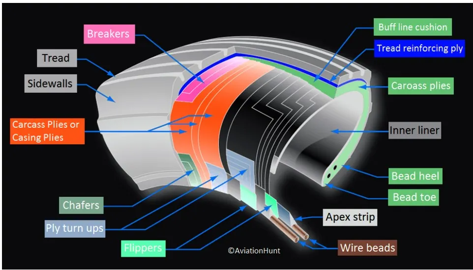
Retreading – Retreading is methods of restoring a worn tyre by renewing the tread area or by renewing the tread area plus one or both sidewalls. Repairs are included in the tyre retreading process.
Load Rating – Load rating is the maximum permissible load at a specified inflation pressure.
Ply Rating – Ply Rating is used to identify the maximum recommended load rating and inflation pressure for a specified tyre. It is an index of tyre strength.
Speed Rating – The speed rating is the maximum takeoff speed to which the tyre has been tested.
Skid Depth – Skid depth is the distance between the tread surface and the deepest groove as measured in the mould.
Aircraft tyres must have an approved speed and load rating and have sufficient clearance when retracted through landing gear to allow for tyre growth. Tyre growth is the increase in the size of the tyre due to centrifugal forces at high speed
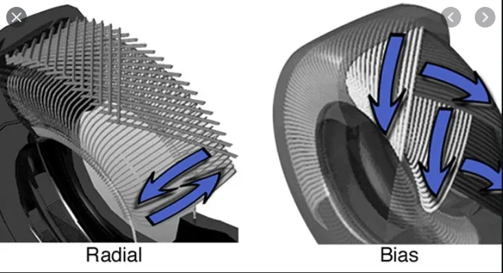
Two types of tires are used in aircraft applications — bias-ply tires and radial tires. Although both types of tires share some similarities in design, there are differences that need to be noted.
Tyre pressure:
Tire inflation is the most critical issue when inspecting installed tires. Although overinflation can damage the tires by causing uneven tread wear, reduced traction, increased susceptibility to cutting, and increased stress on the wheel assemblies, underinflation is by far more damaging. Underinflation produces uneven tread wear and shortens tire life due to excessive flex heating. The bead area of an underinflated tire can be 50 percent hotter than that of a properly inflated one. Heat is damaging to tire rubber compounds and fabrics. It contributes to tread and carcass separations and bead failures.
Ideally, tire pressure should be checked with a calibrated gauge prior to each flight. At a minimum, they should be checked daily. Tire inflation is difficult to determine visually, especially in tandem configurations. Always use a gauge to check inflation. If servicing is required, dry nitrogen should be used due to its inability to sustain combustion. Also, degradation of the casing plies and liner due to oxidation occurs if regular shop air is used. Nitrogen also helps to deter corrosion on the wheel assembly.
It is a good practice to establish a method of recording tire servicing actions. This aids in identifying chronic leakage problems.
Aircraft tires are usually inflated with nitrogen to minimize expansion and contraction from extreme changes in ambient temperature and pressure experienced during flight.Dry nitrogen expands at the same rate as other dry atmospheric gases (normal air is about 80% nitrogen), but common compressed air sources may contain moisture, which increases the expansion rate with temperature.
The requirement that an inert gas, such as nitrogen, be used instead of air for inflation of tires on certain transport category airplanes was prompted by at least three cases in which the oxygen in air-filled tires had combined with volatile gases given off by a severely overheated tire and exploded upon reaching autoignition temperature. The use of an inert gas for tire inflation eliminates the possibility of tire explosion.
Break forces when landing:
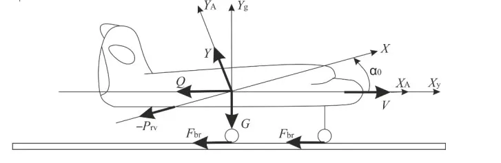
The forces acting on the object during its movement along the runway will change as well in comparison with the forces acting in the phase of flight . The objective of this flight phase is to reduce the speed of the aircraft. Therefore, there will be no aircraft engine thrust (P). Force acting on the aircraft in the direction opposite to its speed will be created. After the aircraft wheels touch the runway the direction of aircraft engine thrust P is reversed (–Prv) as compared to the flight phase. So
during the braking process aircraft engine thrust will be acting in a negative direction only at a certain time interval (–Prv(Δt)). Aerodynamic forces acting on the aircraft in flight will also affect the movement of the aircraft on the runway. Drag Х will continue to act opposite to the speed of the aircraft exerting a breaking effect on it (reducing its speed). The magnitude of drag Х will be reduced in time as it will decrease the speed of the aircraft . There will be created one more aerodynamic resistance force at the stage of aircraft movement along the runway – the force of spoiler resistance Хsp. The force of spoiler resistance Хsp is created by special wing flaps exposed against the flow. There is a new braking force typical of the aircraft movement along the runway. This is the wheel shaft rotation braking force Rbr. This force consists of two components. The first component Ffr1 arises from the existence of force interaction between the surfaces of the runway and the aircraft wheels. It is a rolling resistance force. The magnitude of the rolling resistance force is determined as
`F_(fr1)=k_(fr1)*G`
Where: kfr1=rolling resistance co-efficient
G= vehicle weight.
Rolling Resistance
Rolling resistance coefficient kfr1 depends on the aircraft movement speed V and runway
condition coefficient Cst (humidity, icing, etc.):
`k_(fr1)=(0.0041+0.000041V) C_(st)`
Runway condition coefficient Cst can vary widely. In particular dry smooth concrete Cst will be 1.0.
Rolling resistance force Ffr1 for the case of aircraft movement braking process takes the form
of:
`F_fr1=k_fr1 (G-Y)`
Where Y = Lift magnitude
Lift Y will decrease over time since the braking of the object’s movement leads to the
decrease of its speed (V). The weight of the object (G) will remain the same as in the last moment of
the flight (when the object’s wheels touch the runway). That is, the magnitude of rolling resistance
force Ffr1 is minimal in the aircraft wheels touching point on the runway. When the aircraft is
moving on the runway, rolling resistance force Ffr1 magnitude will increase in time. The second
component of rolling resistance force Ffr2(pd) arises due the object’s wheel shaft rotation braking
facility used by the pilot pressing the brake pedal. This is the driving force of the aircraft’s
movement braking process.
6.To calculate the power to require to pull/push the aircraft by towing vehicle.
The force to move an airplane on an absolute flat runway with no wind at constant low speed is equal to the rolling resistance between the plane and the tarmac and the drag force
Lets consider the Boeing 747, its parameters are as follows
Coefficient of rolling = 0.02
Weight of the aircraft = 183500kg
Frontal area of the aircraft = 158.3m2
Drag coefficient = 0.031
Velocity = 10km/hr
The rolling resistance for the air plane can be calculated as
`F_r=Cm_r a_g`
Ag = acceleration gravity(9.81m/s)
the force required to overcome the rolling resistance can be calculated as
`F_r=0.02*(183500)*9.81`
`F_r=36002.7N`
This force can be delivered by a pulling truck or . Enough weight for the pullers are required to create friction forces against the tarmac that equals the plane rolling resistance.
The friction force for the puller can be calculated to
`F_(Ad)=1/2*ρ*A*V^2*C_d`
`F_((Ad))=0.5*1.25*158.3*10^2*0.031`
`F_(Ad)=306.7N`
Now lets calculate the aircraft tractor forces
Lets take the BEML model BA10G40
Weight of the vehicle = 1100 kg
Frontal area = 3.206m2
Rolling friction coefficient = 0.03
Drag coefficient = 0.4
Rolling resistance force
`F_(Tr)=0.03*1100*9.81`
`F_(Tr)=323N`
Drag force of the aircraft tractor
`F_(Td)=0.5*1.25*10^2*3.206*0.4`
`F_(Td)=80.15N`
Total tractive force required to tow the aircraft = Far+Fad+Ftr+Ftd
`=36002.7+306.7+323+80.15`
`Tractve force=36712.55N`
The power required to tow the aircraft vehicle is = Tractive force x velocity
`P=36712.55*10*5/18`
`P=101979.305 watts`
`P=101.98kW`
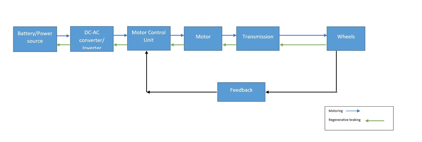
7.To design an electric power train with type of motor, its power rating, energy requirement, to fulfil aircraft towing application. Estimate the duty cycle ratio to control the aircraft speed from zero to highest. Make all required assumptions. Prepare a table of assumed parameters. Draw a block diagram of powertrain.
Lets consider the above results and calculate the duty cycle ratio and energy requirement for the above example
The total power required to push/pull an aircraft by the tow tug is 101.9kW
The total tractive force needed is 36712.5N
Lets assume the The tyre radius as r= 0.35m (215/75R17.5 aircraft tow tug tire)
Gear ratio of G=20
`T=F_t*r/G`
`T=36712.5*0.35/20`
`T=642.46 N-m`
Lets consider the motor AMR dual stack 250-90 AC motor(Remy HVH250)
Motor specifications
Max voltage = 360V/50Hz
Ratted torque = 759N
Ratted Power = 150kW (210HP)
Peak efficiency = 93%
Max input current= 300Amps
Max Rated speed = 10600 rpm
To determine the Duty Cycle ratio:
Input power
`P_i=V*I`
`P_i=360*300`
`P_i=108kW`
Duty cycle ratio:
`δ=P_o/P_i`
`δ=101.98/108`
`δ=94%`
Energy requirement: Consider the battery usage for 5min = 0.08hr
`E=P_o*t`
`E=101.98*0.08`
`E=8.49 kWh`
The energy of battery pack should provide minimum of 8.49kWh of energy
https://www.evwest.com/catalog/product_info.php?cPath=8&products_id=300
https://drive.google.com/file/d/13GhyfGc_oi1ukNaRPIn_WLXwHJJMW8p7/view?usp=sharing