Powertrain for aircraft in runways
PART - A
1. The overall aircraft weight at any point during a flight or ground operation is known as the aircraft gross weight (also known as the all-up weight and abbreviated AUW).
Due to fuel and lubricant consumption, an aircraft's gross weight will drop during a flight. In the PDF file, I have created a list of aircraft along with their MTOW and MLW weight
MTOW - Because of structural or other limitations, an aircraft's maximum takeoff weight (MTOW), maximum gross takeoff weight (MGTOW), or maximum takeoff mass (MTOM) is the maximum weight at which the pilot is permitted to attempt to take off. The MTOW is commonly expressed in kilos or pounds.
The maximum takeoff weight (MTOW) is the maximum weight at which the aircraft has been proved to meet all applicable airworthiness criteria. The MTOW of an aircraft remains constant regardless of altitude, air temperature, or the length of the runway used for takeoff or landing.
MLW - The maximum landing weight (MLW) is the maximum aircraft gross weight that an aircraft can land due to design or operational constraints. The MLW is set to ensure safe landings; if an aircraft weighs too much during touchdown, structural damage or even breakup may occur.
List of Aircraft - https://docs.google.com/spreadsheets/d/1n91mcoHQb2YipINHqvBBbPMLYZQTTG-0/edit?usp=sharing&ouid=117029020878747567865&rtpof=true&sd=true
2. Difference Between Ground speed and airspeed of an Aircraft.
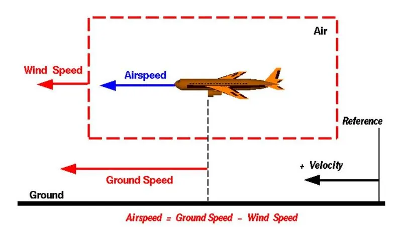
Image Source - https://www.grc.nasa.gov/www/k-12/airplane/move.html
Ground Speed is the relative speed of the aircraft with respect to a reference point on the ground whereas else airspeed can be defined as the speed of aircraft with reference to the speed of air it is flying in.
True airspeed is simply the rate at which an aircraft moves in relation to the air in which it is flying. As a result, it is also the rate at which the air flows around the wings of an aircraft.
The aircraft's ground speed, on the other hand, is its speed in relation to the ground. It's worth noting that the ground speed is horizontal rather than vertical – an aircraft climbing entirely vertically would have a ground speed of zero.
In other words, while airspeed determines whether an aircraft has enough airflow to fly, ground speed determines how quickly an aircraft arrives at its destination.
Effect of Wind speed on Ground Speed -
The important quantity in the generation of lift is the relative velocity between the object and the air, which is called the airspeed. Airspeed cannot be directly measured from a ground position but must be computed from the ground speed and the wind speed. Airspeed is the vector difference between the ground speed and the wind speed.
Airspeed = Ground Speed - Wind Speed
On a perfectly still day, the airspeed is equal to the ground speed. But if the wind is blowing in the same direction that the aircraft is moving, the airspeed will be less than the ground speed.
3. It is not recommended to use the engine power of an aircraft on the ground because of the following reasons -
- The cost of the aircraft fuel is high, hence, it is impractical to use the aircraft engine on the ground as it will result in wastage of fuel.
- if reverse thrusters are used for taxing purposes debris on the ground may damage the infrastructure around it
Due to the following reasons, it is not advisable to use the engine of aircraft for taxing purposes,s and towing tractors are used.
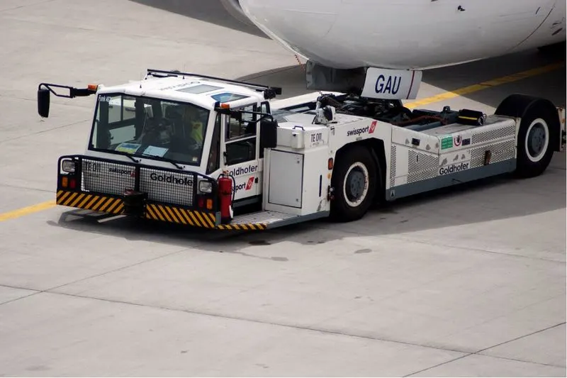
4. Pushback trucks or Towing tractors are used by the ground crew to guide the aircraft on the runway. Conventionally a towbarless link is used to connect the nose of the aircraft to that of a towing truck.
5. Take-off power -
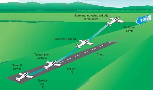
- Take-off is the phase during flight. When an aircraft enters into aerospace from the ground, the take-off phase is achieved. To achieve the take-off the aircraft has to attain enough ground velocity so that air drag can provide lift to the body of the aircraft.
- The take-off velocity is dependent on various factors such as air density, the weight of the aircraft, shape of the aircraft. An aircraft engine is used to provide the power required to attain the take-off speed.
- Generally, small aircraft use full power during the take-off phase whereas large commercial aircraft use less engine throttle to achieve the same due to safety and economic reasons.
Tire design of an Aircraft -
A plane's tire is built to withstand extremely heavy loads during landing, takeoff, taxing, and parking. The number of wheels required for aircraft grows in proportion to the aircraft's weight, as the weight of the aircraft must be distributed more evenly.
Aircraft tires operate under extreme conditions, carrying up to 340 tonnes and accelerating at speeds of over 250 km/h at takeoff, as well as enduring varying environmental stresses while in flight and taxiing.
Design and Construction -
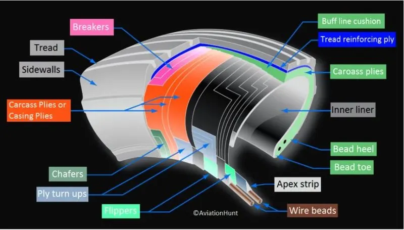
The tire is made up of carcass plies. They are also known as casing plies. An aircraft tire is designed specifically for its intended use.
- They support an aircraft's weight while it is on the ground.
- It also provides the necessary traction for an airplane's braking and stopping.
- Tires also help to absorb landing shock and cushion the roughness of takeoff, roll-out, and taxi operations.
Unlike an automobile or truck tire, it does not have to carry a load for an extended period of time. An aircraft tire, on the other hand, absorbs the high impact loads of landing and can operate at high speeds for a short period of time when necessary.
Retreading -
Retreading refers to the process of restoring a worn tire by renewing the tread area or the tread area plus one or both sidewalls. Repairs are part of the retreading process.
Load Rating -
The maximum allowed load at a given inflation pressure is referred to as the load rating.
Ply Rating -
Ply Rating is used to determine a tire's maximum recommended load rating and inflation pressure. It is a tire strength index.
Speed Rating -
The speed rating is the maximum takeoff speed to which the tire has been tested.
Skid Depth -
kid depth is the distance between the tread surface and the deepest groove as measured in the mould.
Aircraft tires must have an approved speed and load rating and have sufficient clearance when retracted through landing gear to allow for tire growth. Tire growth is the increase in the size of the tire due to centrifugal forces at high speed
Difference between Bias-ply and Radial tires -
Radial tires -
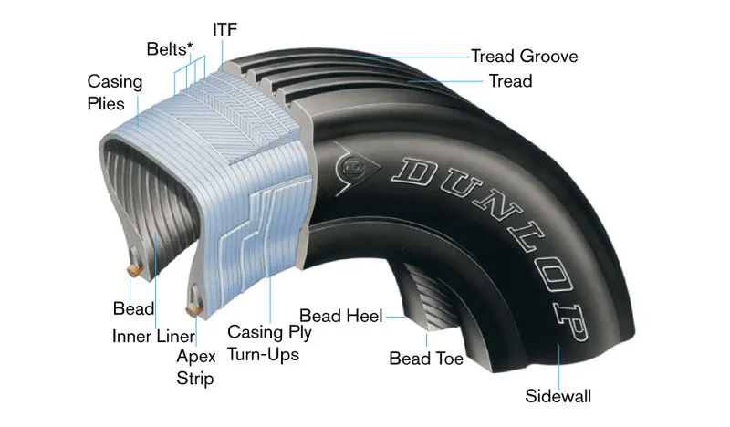
- Due to stiffer tread in radial tires, they distribute weight evenly. These results provide consistent contact patches and greater traction, which means the tires wear less and longer tread life.
- Most radial tires are resistant to penetrations and cuts, especially in the tread area due to their unique construction process. In fact, only a small portion of the radial tire will be affected in case of any damage.]
- Due to stiffer tread in radial tires, they distribute weight evenly. These results provide consistent contact patches and greater traction, which means the tires wear less and longer tread life.
Bias-Ply -
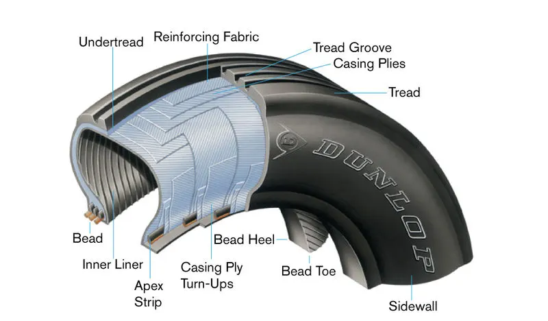
- the bias-ply tire has the fabric bias oriented with and across the direction of rotation and the sidewall. Since fabric can stretch on the bias, the tire is flexible and can absorb loads. Tire strength is obtained by adding plies.
- Bias-ply tires are cut-resistant in the sidewall area. However, if there is any cut in the tread area, it can affect only a small portion of the tire.
- While bias-ply tires do not offer as much smoothness in terms of riding quality, their strong and stable sidewalls more than makeup for it, especially this use in heavy-duty carriage trucks and buses.
Rolling Resistance -
The rolling resistance can be expressed by the generic equation
Fr = `mu*W` (1)
where
Fr = rolling resistance or rolling friction (N, lbf)
`mu` = rolling resistance coefficient - dimensionless (coefficient of rolling friction - CRF)
W = m ag
= normal force - or weight - of the body (N, lbf)
m = mass of body (kg, lb)
ag = Acceleration due to gravity (9.81 m/s2, 32.174 ft/s2)
The rolling resistance coefficient - c - is influenced by different variables like wheel design, rolling surface, wheel dimensions and more.
Tire pressure of an aircraft -
Depending on the weight of the plane and the number of tires the usual operating range for aircraft tire is 200 to 300 psi.
Brake force on aircraft -
All modern aircraft are fitted with a braking system to assist in slowing and stopping when on the ground. Brakes are used not only to decelerate during a landing run, but also to hold the aircraft during an engine run-up, and in some cases to steer the aircraft through differential braking.
The science behind braking -
Brakes work by dissipating energy as heat through the action of friction. An aircraft wheel rotating at speed possesses a large amount of kinetic energy. By contacting the wheel with a semi-metallic or ceramic brake pad, an enormous amount of heat is generated as a result of the friction between the two contacting surfaces.Brakes are usually hydraulically actuated, but in some cases may be operated through a mechanical actuation system.
- Disc brake operation -
Disc brakes are the most common braking system in use today and consist of a disc that rotates with the wheel and a stationary brake caliper that actuates onto the disc to affect a braking force. The caliper is the name given to the assembly that contains the brake pads and piston(s). The pads are connected to the piston which actuates under hydraulic pressure applied either through a toe brake or a brake lever in the cockpit.
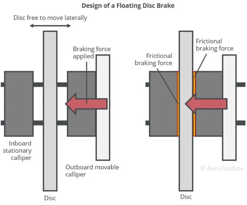
Depending on the need the number of discs can be varied in a disc brake assembly for an aircraft.
- Thrust reversal -
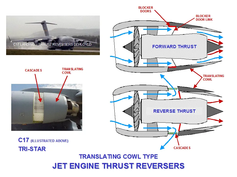
A thrust reverser is a vital component of many jet aircraft that enables for faster landing deceleration. A thrust reverser system assists the jet in slowing down after touchdown by operating against the aircraft's forward motion. This decreases brake wear and allows for shorter landing distances. Thrust reversers are critical to the safety and performance of an airplane.
thrust reverser systems are most commonly found on passenger airplanes and large cargo jet aircraft.
While some aircraft, such as military planes, may use it while in the air to perform steep descents, reverse thrust is typically only used when on the ground.
- Mechanical Spoilers -
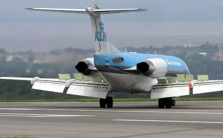
Mechanical spoilers are widely used to apply brakes on the aircraft aerodynamically. A mechanical spoiler can apply the brakes on an aircraft in two possible ways.
1. By increasing the aerodynamic drag force acting on the aircraft
2. By increasing the downward load on the aircraft indirectly and therefore increasing the efficiency of mechanical braking.
PART B
7. Calculating Force and power on an aircraft with necessary assumptions
Theory -
In this project, we have assumed the following data -
Mass of plane - 40000 kg
Mass of towing vehicle - 1000 kg
Friction Coefficient - 0.015
Drag coefficient - 0.75
Using MS excel we have calculated the following data,
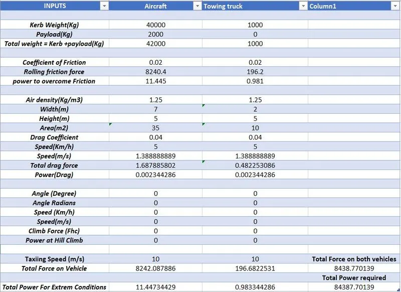
Force calculated is in Newton and Total power in kW.
From the above data, we can see that the total force acting on the aircraft while taxiing is
8242.08 N +196.68 N = 8438.77 N
and the total power required to pull/push the aircraft is
`P = Ft*v`
`Ft`= 8438.77 N
`v`= 10 m/s`
`P`= 8438.77*10 = 84387.70 w or 84.387 kW.
Simulink model for force and power calculation -
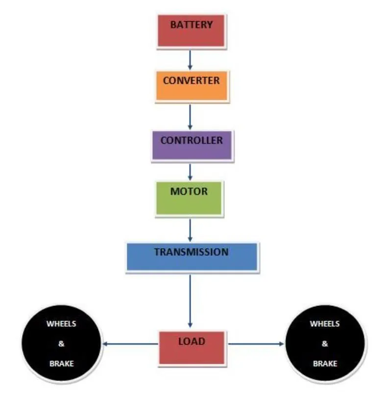
7. . Design an electric powertrain with the type of motor, its power rating, and energy requirement to fulfill aircraft towing application in Simulink. Estimate the duty cycle range to control the aircraft speed from zero to highest. Make all required assumptions. Prepare a table of assumed parameters. Draw a block diagram of the powertrain.
Let the power requirement be 85kw
for a 20 min taxing operation, the Energy required from the battery is E = power*Time
E = 85*(20/60) = 85*(1/3) = 28.33 kw-h
Torque - (Ft*r)/G
where,
Ft - total tractive force
r - radius pf wheel in m
G - gear ratio
T - (8438 N * 0.38 m)/6 = 528.70 N-m
Duty Cycle - the duty cycle can be calculated by equating on time of the switch to that of total time i.e,
`(on)/(on+off)`
or
in voltage terms,
`(Vi)/(Vo)`= Duty cycle
In this case, the battery voltage is taken as 600 V and the required voltage is 540V
`540/600 = 0.9`
hence, a 90% duty cycle is required for the operation of the Drive.
Motor Data -
For this model Data from Higen 600 N-m Truck motor is Suitable
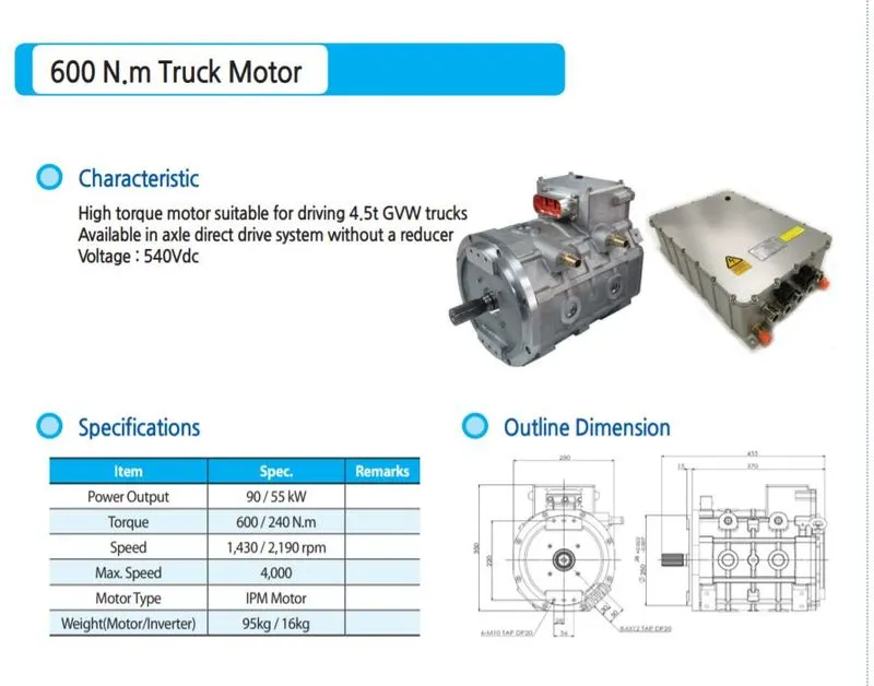
Motor Characteristics -
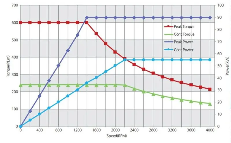
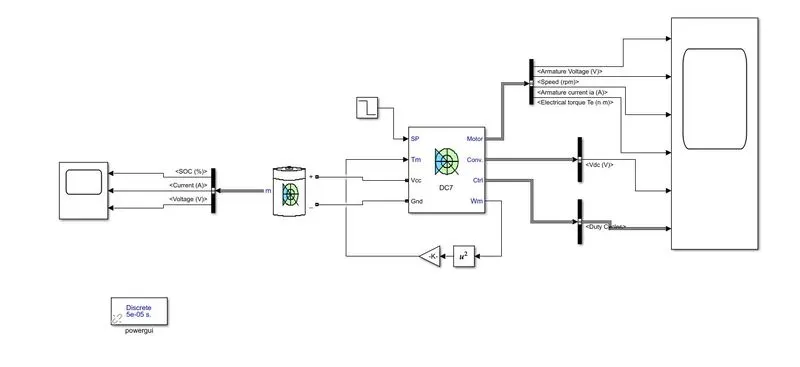
Simulink Model -
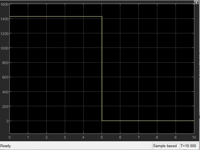
Input Signal -
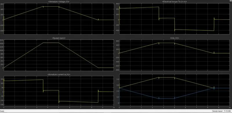
Output -
Drive link - https://drive.google.com/drive/folders/1qzooGPaEkMakexkLQDhNoeCqYpIUyUvE?usp=sharing