Project-1: Modelling an electric Car with Li-ion battery
Modelling an electric car with LI-ion battery
Aim:
Create a MATLAB model of electric car which uses lithium ion battery and suitable motor. Choose suitable blocks from Simscape or Powertrain block set. Implement the vehicle speed control using PI controller and generate brake and accelerator commands. Avoid using readymade driver block for speed control.
Prepare a report about your model including following:
Objectives, System level configurations, Model parameters, Results, Conclusion.
Electric Vehicles – 8 Different Types
Electric Vehicles can be broadly classified into 8 different types.
- Plug-in Electric Vehicle
- On- and Off-road Electric Vehicles
- Space Rover Vehicles
- Seaborne Electric Vehicles
- Airborne Electric Vehicles
- Electrically Powered Spacecraft
- Range-extended electric vehicle
- Railborne Electric Vehicles
Plug-in Electric Vehicle (PEV)
A plug-in electric vehicle (PEV) is any motor vehicle that can be recharged from any external source of electricity, such as wall sockets, and the electricity stored in the Rechargeable battery packs drives.
Plug-in Electric Vehicles can be further categorized into
- Plug-in Hybrid Electric vehicles, (PHEVs)
- Battery electric vehicles (BEVs)
Plug-in Hybrid Electric Vehicles (PHEV)
- A plug-in hybrid electric vehicle (PHEV) is a hybrid electric vehicle whose battery can be recharged by plugging it into an external source of electric power, as well as by its on-board engine and generator.
- Most PHEVs are passenger cars, but there are also PHEV versions of commercial vehicles and vans, military vehicles, utility trucks, trains, motorcycles, buses and mopeds.
Battery Electric Vehicles
- A battery electric vehicle (BEV), pure electric vehicle, only-electric vehicle or all-electric vehicle is a type of electric vehicle (EV) that exclusively uses chemical energy stored in rechargeable battery packs, with no secondary source of propulsion.
- Battery Electric Vehicles (BEV) thus have no internal combustion engine, fuel cell, or fuel tank.
- Some of the broad categories of vehicles that come under this category are trucks, cars,buses, motorcycles, bicycles, forklift etc.
Advantages of Electric Vehicles
Electric Vehicles – Environmental Advantages
Electric cars (or electric vehicles, EVs) have several environmental benefits compared to conventional internal combustion engine cars.
- Have the potential to reduce greenhouse gas emissions
- Reduce dependence on petroleum
- Reduce health effects from air pollution
- Reduce dependence on petroleum
- They produce little or no tailpipe emissions
Electrical Vehicles – Better Energy Efficiency
- Internal Combustion engines will consume fuel even when the vehicle is stationary, whereas in electrical vehicles, the energy is not consumed when it is stationary.
- Electrical Vehicles ‘tank-to-wheels’ efficiency is about a factor of 3 higher than internal combustion engine vehicles
Electric Vehicles – Mechanical Advantages
- They can be finely controlled and provide high torque from rest, unlike internal combustion engines, and do not need multiple gears to match power curves. Hence it removes the requirement for gearboxes and torque converters.
- Lesser vibration
- Lesser noise
- Electric motors are mechanically very simple and often achieve 90% energy conversion efficiency over the full range of speeds and power output and can be precisely controlled.
Electric Vehicles in India – Government Schemes and Initiatives for Promotion of Electric Vehicles
- In February 2019, the Union Cabinet cleared a Rs 10,000-crore programme under the FAME-II scheme. This scheme came into force from April 1, 2019. The main objective of the scheme is to encourage faster adoption of electric and hybrid vehicles by offering upfront incentives on the purchase of electric vehicles and also by establishing necessary charging infrastructure for EVs.
- In 2017, Transport Minister Nitin Gadkari made a statement showing India’s intent to move to 100 percent electric cars by 2030. However, the automobile industry raised concerns over the execution of such a plan. The government subsequently diluted the plan from 100 percent to 30 percent.
- In 2013, India unveiled the ‘National Electric Mobility Mission Plan (NEMMP) 2020’ to make a major shift to electric vehicles and to address the issues of national energy security, vehicular pollution, and growth of domestic manufacturing capabilities. The scheme was to offer subsidies and create supporting infrastructure for e-vehicles.
Impact of Electric Vehicles on Employment and Economic Growth
- The battery manufacturing industry in India can become bigger than the total amount spent on import of crude oil. This would provide a huge boost to the Indian economy.
- There needs to be a careful plan to hand-hold mini and micro auto component industries, which employs large numbers of people. Many of these companies won’t survive as Electric Vehicles replaces petrol/diesel vehicles. Hence it is imperative to help them during the transition phase to EV components manufacturing.
- European Climate Foundation has estimated that through reducing oil demand by more efficient electric cars, employment will increase by 5,00,000 to 8,50,000 by 2030.
- As per one of the studies, net private and social benefits are estimated between $300 and $400 per Electric vehicle.
- The revenue loss for governments from the taxes on the oil sector is expected to be replaced by higher tax revenues in other economic sectors.
- EVs will create opportunities in durable and lightweight thermoplastics, higher demand for electricity, storage, and many others.
Electric Vehicle Policy (EV) 2020
The Delhi Government has announced the Electric Vehicle Policy 2020 where the emphasis will be given on replacement of two-wheelers, public transport and shared vehicles and goods-carriers instead of private four-wheelers, with Electric Vehicles (EVs).
Given below are the features of the Electric Vehicle (EV) Policy 2020:
- As per this policy, the focus will be shifted to e-mobility, including e-autos, e-buses, etc. The Government will also offer low-interest rate loans to buy electric vehicles
- A state EV fund will be introduced to cover up the expenditure of the EV Policy
- The main objective of the Electric Vehicle Policy is to reduce air pollution and curb the health emergency issues in the state of Delhi
- These e-vehicles will also reduce the expense of buying motor vehicles
Vehicle body subsystem:
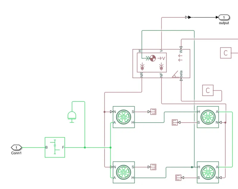
The following blocks that were used for the creation of the model
- Tire (magic formula)
- Vehicle body
- Simple gear
- Inertia
- Ps – simulink converter
- Ps – constant
- Ps – terminator
Tire (magic formula):
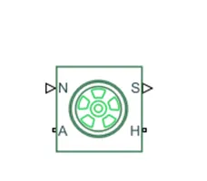
The magic tire block models a tire with longitudinal behaviour which is given by a magic formula an empirical equation based on four fitting coefficients. Under constant or variable conditions this block can model tire dynamic. The longitudinal direction of the tire is same as the direction of motion as it rolls on the pavement.
Connection A is referred to the mechanical rotational conserving port for the wheel axle connection H is the mechanical translation conserving port for the wheel hub through which the thrust is develop by the tire which is applied to the wheel. Connection N is a physical signal input port the applies the normal force is considered positive. Connection S is a physical signal output port reveals the tire slip.
Vehicle body:
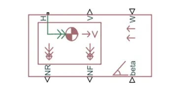
This vehicle body block is a representation of a two-axle vehicle body in longitudinal motion. The vehicle can have the same or different number of wheels on each axle. The vehicle can have a centre gravity that is at or below the plane of travel. This block accounts for body mass aerodynamic drag road incline and weight distribution between axles due to acceleration and road profile which optionally includes pitch and suspension dynamics. The vehicle does not move vertical relative to the ground.
Connection H is the mechanical translational conserving port which is associate with the horizontal motion of the vehicle body. The traction motion developed by the tires should be connected to this port.
Connections V, NF and NR are physical signal output ports that represents vehicle velocity and front and rear normal wheels force are considered positive if acting downward. Connections W and beat are physical signal ports that signify headwind speed and road inclination angle respectively
Simple gear:
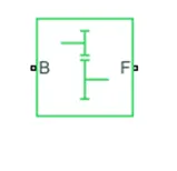
The simple gear box represents the gearbox that constrains the connected driveline axes of the base gear B and then follower gear F to corotate with a fixed ratio that is specified connections B which is the base and F the follower are mechanical rotational conserving
Inertia:

Ps - Simulink converter:
Explanation of vehicle body subsystem:
- Transmission is an important aspect of the vehicle which is used to supply the propulsion power from the motor and then the wheels.
- For the certain of the above subsystem the following blocks that were tire (magic formula) block simple gear block, vehicle body, inertia block, PS Simulink converter, Ps constant, Ps terminator so as to create the base for the model
- First the wheels of the vehicle are modelled by using the tire block. Four tire blocks are created for there are various parameter which can be edited according to the requirement. During the simulation default parameters of the tire block were used.
- Then all the ports of each tire block are connected with each other. Port A represents axle so the rear wheels A ports are connected with each other which signifies that they are on the same axle. Similarly for the front wheels are also connected to the same axle.
- Then the H port represents the hub and all the H ports are connected to each other.
- The N and S port represents the normal force and slip of the tire respectively. So the N port of both rear wheels normal force. The port S represents the slip occurring in the wheel. The port can be connected or can be ignored. In the above model it is connected to a Ps terminator block which terminates the physical signal outputs
- Then a vehicle body diagram is used which represents the vehicle dynamics where there are various parameters which can be changed according to the requirement.
- The NR and NF port in the vehicle body represents the normal force on rear and front tires respectively. So the N port of the front and rear tires are connected with NR and NF ports accordingly.
- The H port in the vehicle body is associate with the horizontal motion of the body and is connected to the H port of all the tires
- The W and BETA port represents the wind speed and road inclination angle which can be entered as an input. In above model the W and the BETA port are connected to a PS constant block since we have assumed both to be zero
- The port V in the vehicle body represents the velocity output from the vehicle so this is connected to the output port since the power from the motor has to be transmitted to the wheels a transmission block is used which is a SIMPILE GEAR BLOCK. This block is connected to the rear wheel axle since the model is considered as a rear wheel drive and to this inertia block is added
- Finally the subsystem is modelled where the input of the system is the power given to the simple gear box and output is the velocity of the vehicle
Motor controller subsystem model:
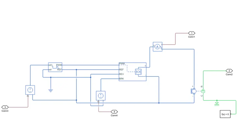
The following blocks that were used for the creation of the model are:
- Controlled voltage source
- Controlled PWM voltage
- H-bridge
- Current sensor
- Solver configuration
- Dc motor
- Mechanical rotational sensor
- Electrical reference
- Scope
Controlled voltage source:
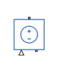
The controlled voltage source depicts an ideal voltage source which is powerful enough to maintain the specified voltage at its irrespective of the current flowing through the source
The output voltage V=Vs where Vs is the numerical value presented at the physical signal port
Controlled PWM voltage:
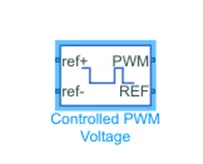
The controlled PWM voltage block represent a pulse width modulate (PWM) voltage source. This block has two modelling variants by right clicking on the block and then selecting simscape and then block choices which are electrical input ports and PS input
Electrical input ports
PS input
Electrical input ports:
This block calculates the duty cycle which is based on the reference voltage across ref+ and ref- ports. This modelling variant is default
PS input:
Specifies the duty cycle value directly by using an input signal port. For electrical inputs ports variant of the block the duty cycle calculate is:
100*V ref-V min/Vmax-V min%
Where,
V ref is the reference voltage across ref+ and ref- ports
V min is the minimum reference voltage
V max is the maximum reference voltage
H- bridge:
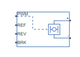
H-bridge block output is a controlled voltage that depends on the input signal at the PWM port. The H-bridge is connected to pulse width modulation for controlling of the voltage signals and the output of the H-bridge is connected to the terminals to provide the controlled voltage to the D.C motor
The ports in H-bridge are:
PWM- this stand for pulse which provides the voltage pulse to H-bridge either in PWM or average mode.
REF – is the floating zero-volt reference
REV – voltage that controls when to reverse the polarity of the H-bridge block output
Current sensor:
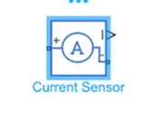
The current sensor block represents an ideal current sensor. It is a device that converts current measured in any electrical branch into physical proportional to the current. The connection + and – in the block are electrical conserving ports through which the sensor is inserted in the circuit
Solver configuration:
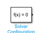
The solver configuration block requires solver settings information for simulation. The block specifies the solver parameters that the model requires before running the simulation.
D.C motor:
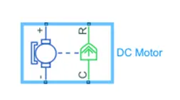
There are 2 sides to the block as seen above the mechanical side and electrical side. The mechanical side has 2 ports, c and R. the C refers to casing and R for the rotation of the rotor. The electrical side has a positive and negative terminal for the voltage to be applied reference because it will be stationary. The R port will be connected to the simple gear of the vehicle body block
Mechanical rotational reference:

The mechanical rotational reference block represents a reference point or frame for all mechanical ports
Electrical reference:

The electrical reference ground represents an electrical ground. Electrical conserving ports f all the blocks that are directly connected to the ground must be connected to an electrical reference block
Scope:

Scope is used for viewing the graph of the signals after the simulation is run
Explanation of the motor controller subsystem:
- The motor controller subsystem contains mainly of H-bridge and a controlled PWM voltage block D.C motor current sensor and controlled voltage source
- A controller is needed to control the motor according to the needs which is why a controller block is used which is the H-bridge
- H-bridge is used to supply power from the battery of the DC motor H- bridge has four a switches that given the controller DC voltage supply to the DC motor that can control the supply of voltage
- In H-bridge block parameters there are two option for simulation mode to chooses from either averaged or PWM but averaged mode is chosen since the simulation time is in mins or hours and it is faster as compared to PWM mode
- In the H-bridge block there is a PWM input can be given to this port. The REF and REV ports are grounded using electrical reference block. This is done to prevent reverse operation of the motor. BRK port is connected to a controlled voltage source which helps in carrying out regenerative braking
- PWM signals is given to the H-bridge block by using controlled voltage block this block helps in creating PWM signals which are generated according to the variable voltage
- The PWM and REF port of the controlled PWM voltage is connected to PWM and REF port of the H-bridge. The ref-port is grounded since we don’t need negative voltage and is connected to the REF and REV port of the H-bridge. The ref+ port is connected to controlled voltage block so that the input voltage is the same always.
- Controlled PWM voltage block is connected to the input PWM port in the H-bridge block
- This block will apply pulses and based on these pulses from the fixed battery voltage variable output voltage will be available to the motor and the motor torque and motor speed are changed
- Now an approximate motor is selected for the electric vehicle so a C motor block is used to represent to DC motor. In the DC motor block parameters were changed like the rated DC voltage of the motor rated load speed rated speed according to the vehicle needs
- The motor block has 4 ports -, +, c and R where – and + ports are the motor terminals where the power supply is connected and the positive torque is from port c to R and port C is considered as fixed end of motor and the motor so it connected to the mechanical rotational reference block to which a solver configuration block is added. The + port of the DC motor is connected to the H-bridge through current sensor and the negative port of the DC motor is connected to negative of the H-bridge as well as the REF port of the DC motor is connected to negative of the H-bridge. The port R is connected to vehicle dynamic input which is the simple gear box
- Finally the subsystem is created with the following blocks and the subsystem will control the power supply to the DC motor
Distance calculation:
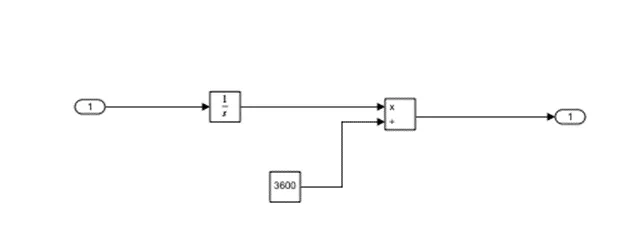
In the above model for distance calculation the input is taken from the velocity feedback and it is integrated block and divided by 3600
Energy consumption & SOC%:
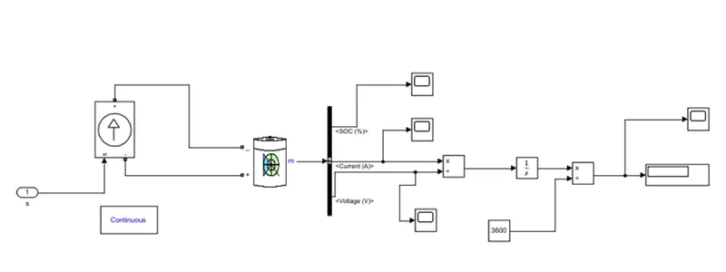
State of charge is defined as the measurement of available charge in the battery. When the battery is fully charged it is considered to have 100% and when it is 0% it is said to be discharge. After the simulation is run we get an estimate of the current and S.O.C of the battery with respect to time
The following blocks that were used for the creation of the subsystem:
- Controlled current source
- Battery
- Bus selector
- Power gui
- Product
- Integrator
- Constant
- Divided
- Scope
Controlled current source:
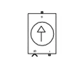
The controlled current source block converts the Simulink input into equivalent current source. The positive current direction is as shown in the block icon
Battery:
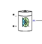
This block creates a genetic dynamic model parameterized to represent most popular types of rechargeable batteries
Lithium-ion batteries require fewer maintenance and operation costs are less. The average life of a lithium-ion battery is 8 years. The lithium-ion battery has significant environment benefits over fossil fuels. With increase in electric vehicle we have seen an immediate impact on the reduction of carbon emission
Bus selector:
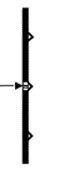
The output of the block specifies subset of elements of bus at its input. The block can output the specified elements as separate signals
Power gui:
The power gui block chooses the following methods to solve the circuit:
- Continuous which uses a variable step solver from Simulink
- Discretization of the electrical system for a solution at fixed time steps
- Phasor solution
The block is used for steady state and simulation results analysis and also for advanced parameter design. This block is required to simulate Simulink model that contain simscape electrical specialized power subsystem blocks
Explanation of energy consumption & SOC % subsystem:
- This subsystem consists of Lithium-ion battery block a controlled current source bus selector and power gui block
- The current sensor is connected to the controlled current source through a PS Simulink converter where the + connection of the controlled source is connected to the negative port of the battery and the – connection is connected to the positive port of the battery
- From the M port of the battery block we obtain the S.O.C ampere and voltage values these values are extracted using bus selector when it is connected to the M port
- The ampere and the voltage output is connected to a product block and multiplied so as to get the energy consumption in watts
- This output is then connected to an integrator block which will add those watts over the simulation time and gives the value in watt second
- This watt second value is then converted to watt hour by dividing by 3600 to obtain the energy consumed by the electric rickshaw during the course of the simulation
Simulation model of an electric vehicle:
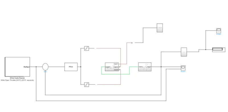
The following blocks that were used for the creation of the model
- Driver cycle source (wide open throttle)
- Sum block
- PID controller
- Saturation block
Drive cycle source (wide open throttle):
This is wide open throttle drive cycle in which the vehicle run at as constant speed of 45 Km/hr for a distance of 22.56 km. the simulation run for the drive cycle is 2010 seconds
Sum:
PID controller:
Saturation block:
Explanation of the model:
- In order to measure the speed of the electric vehicle model scope block is used where 2 input ports are made. One port takes the output velocity signal from the vehicle subsystem block and another port takes the output signal from the drive cycle
- The drive cycle used is wide open throttle which is connected to a sum block and instead of a longitudinal driver block a PID controller where the upper and lower limits are given for acceleration as 1 and 0 and for deceleration 0 and -1. The saturation blocks for acceleration and deceleration are connected to separate controlled voltage source through Simulink-PS converter
- The area under the velocity time graph deposits the distance travelled by the vehicle this means that integration is done with respect to time which gives the distance travelled Integrator block is used to Integrate the velocity signal that is the output from the subsystem. After the integrator block divide block is used along with constant block with the value of 3600 in order to convert the integrated speed signal which is in kilometres per hour by 3600 which gives the distance travelled in kilometres
- Finally, the electric rickshaw model is completed and one the simulation is run we get the following results