Project-1: Modelling an electric Car with Li-ion battery
Aim:- Modelling an electric Car with Li-ion battery
Objective:-
Create a MATLAB model of electric car which uses lithium ion battery and induction motor. Choose suitable blocks from Powertrain block set. Prepare a report about your model including following:
Objectives, System level configurations, Model parameters, Results, Conclusion
Answer:-
System Level Configuration-
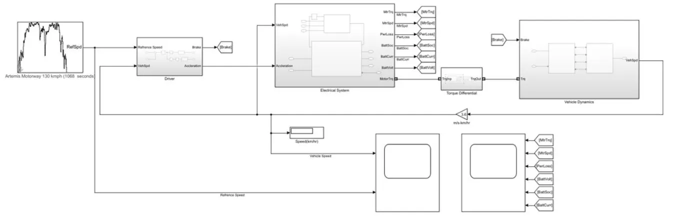
Electric Vehicle Model-
The Electric vehicle Model is represented by using MATLAB/SIMULINK, this model is a complete representation of an Electric Vehicle which is been build using powertrain block sets.
This model has vehicle dynamics and electrical system, the vehicle dynamics contains subsystem relates to the vehicle body and tire whereas the electrical system contains a subsystem related to motor and battery pack.
This subsystem contains various other components, lets's understand each and every component in details.
Vehicle Dynamics-
Vehicle Dynamics is nothing but the study of the vehicle in motion and how the vehicle behaves in motion. The Vehicle Dynamics consist of two main subsystems which are
1. Vehicle Body 2. Wheels
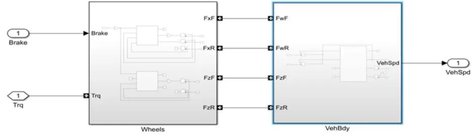
1. Vehicle Body-
In this model vehicle body (1DOF) longitudnal block is implemented. This bolck helps us to determine the vehicle inertia and drag load. There are mainly two forces acting on the wheels which are Longitudnal Force and Normal Force. These forces act on the rear and front of the wheels, the longitudnal forces on rear and front is given by (FwF & FwR). Whereas the normal forces are given by (FzF & FzR). This forces is connected to the respective axle of the wheels.
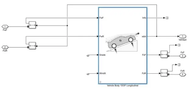
The Vehicle Body consist of grade and wind input ports which can be used to simulate slope and wind drag but this port are been grounded to minimize the complexity of the model. The Xdot output port is a longitudnal force in the X-Axis which acts as the velocity/speed of the vehicle in m/s.
Parameters of the Vehicle Body-
1. No. of Wheels on the Front/Rear = 2
2. Mass of the Vehicle = 1500(kg)
3. Frontal Area = 4m^2
4. CG hieght above Axle = 0.35m
5. Drag cofficient = 0.3
Vehicle & Brakes-
The wheels used in this vehicle are longitudnal wheels have brakes of disc type brakes have great stopping power and cause less wear and tear and provide precises braking. This block implements the longitudnal behaviour of actual wheels.
This vehicle is rear wheeled drive hence the axle torque is connected to the rear of the wheels and the axle of the front wheel is Grounded.
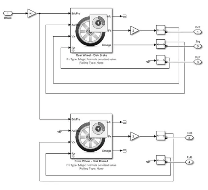
The longitudnal forces of the tires are set to magic formula constant the magic formula is a separate from of a characteristics function of stiffness, shape, peak and curvature. (BCDE)
Magic Formula is given as (`F_F=f(k,F_Z)=F_ZDsin(Ctan-1[{B_K-E[B_K-tan-1(B_k)]}])`
The Brake input command for the front and rear wheels are connected commonly as one input port. Omega is the angular velocity of the wheels in the y-axis, hence this force is considered as torque input to the wheels.
Parameters for Wheels-
1. Wheels Inertia = 0.8kg*m^2
2. Wheel Radius = 0.3m
3. Tire Pressure = 220000
4. Brake Pad Radius = 0.117m
Torque Differential-
The Torque Differential block is connected between the motor shaft and the axle of the wheels the block consist of an open differential block and a torsional compliance. The open differential block is basically a set of planetary gear system it matches the drive shaft to the crown gear and the transmission driveshaft to the wheel axle. The block uses a coordinate system that produces a positive tire and vehicle motiom.
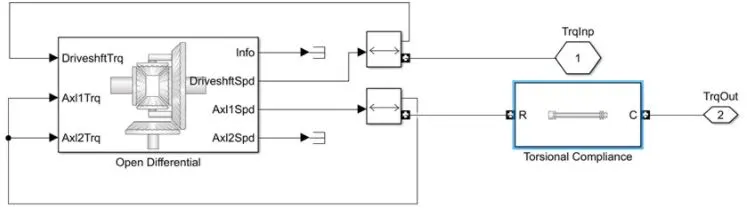
Input for the open differential is drive shaft torque which accepts input from the motor drive shaft and axle torque which are connected to the axle of the wheels. on the other side torsional compliance is basically a spring damper which is a shaft that connect between the open differential and axle wheels.
Parameters for Torque Differential-
1. Drive Shaft Ratio = 3.4
2. Axle 1 Inetia = 0.3 kg*m^2
3. Carrier Inertia 0.25kg*m^2
4. Torsional Stiffness = 5000 n*m*s/rad
5. Torsional Damping = 10 N*m*s/rad
Electrical System-
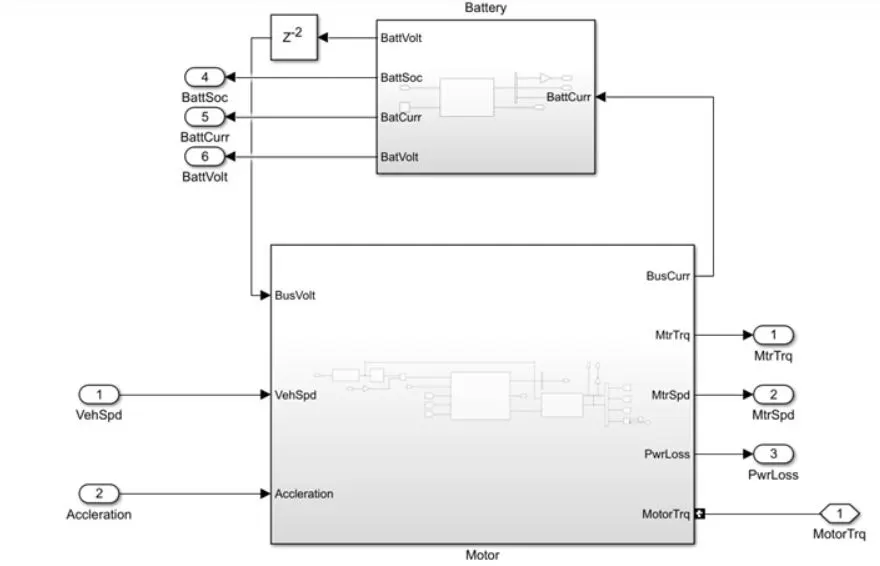
The Electrical system is the most important system in the whole drive cycle. The Electrical System is subdivided by-
1. Motor (Induction Motor)
2. Battery (Lithium ion Battery)
1. Induction Motor and Induction Motor Controller-
This vehicle uses a three-phase induction motor as the main driving source. The Induction Motor also called as a synchronous motor. It is an AC motor that works on the principle of electromagnetic induction most of the electric car use IM as their man drive because as they offer high power torrque density and speed range and compact size.
Induction Motor performance in field weakening constant power region but IM has low speed performance efficiency, heat loss which lead to low power factor and efficiency. Hence to control the speed and torque of the motor we need to use an IM controller. The IM controller blocks implemented a torque based field oriented controller with an outer speed loop control. The controller also implemets equation for speed control, torque determination regular some basic formula that the blocks implements are-
To calculate speed, frequency and poles formula required to calculate losses losses in the motor
`eta_(sync)=120`f/p Stator Copper Losses
`eta_(sync)= Synchronous Speed` `P_(sc)-3I^2R_s`
F = frequency Rotor Copper Losses
P = Poles `P_(RC)=3I^2Rr`
Required Mechanical Power
Motor Slip Calculation `P_(mech=P_(RC)(1-`S/S)
`S=(eta_(sync)-eta_m)eta_(sync)*100`
`eta_m = Mechanical Shaft Speed`
To Calculate Torque and Speed
`T=P/omega_m`
T = Torque(N/m)
P = Power in KW
`omega_m` rad/min
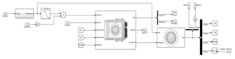
The corresponding phases (A,B) is connected to the motor controller the speed of the motor is constantly regulated by its controller closed loop speed control (SpdFdk port).
The vehicle speed in(m/s) is converted to motor speed in (rad) by the help of unit conversion and signal specification block. Taking a product of motor speed and acceleration a torque command is genereted. The lookup table takes input as vehspd in rad which is then scaled by accelerator command and the product of two is implemented as a torque command.
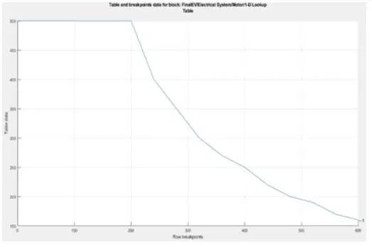
Torque Command Data
The resultant motor torque signal is obtained from the bus selector.
Parameters for Induction Motor/Controller-
1. Motor type = 3 Phase Induction Motor
2. No of Poles = 2
3. Stator Resiststance = 1.77`Omega`
4. Rotor Resistance = 1.34 `Omega`
5. Inductance = 0.368H
6. Frequency = 60Hz
7. Line to Line Voltage = 460v
8. Torque at rated current = 12.646
9. Rated slip = 0.017
10. Inverter Efficiency = 98%
Lithium-Ion Battery-
The Battery is the energy source of any system the battery used in the system is a Datasheet battery which implements a model for the lithium-ion battery. The question arise that why most of the EV uses lithium-ion cells as a source, like any other battery because battery like a lead acid battery which required constant maintenance and monitoring, hydrogen cells which are quite bulky and expensive also capacitor banks are used as a battery pack but they have a high discharge rate and drain quickly.
Hence the Lithium-Ion Battery eliminates all such disadvantages and requires fewer maintenaince and operational cost are less.
Longevity- The average lithium-ion battery life span for large capacity is mre than 8 years. Safety-reduce the risk of accidents by eliminating exposures to flammable fuels able to withstand even in the high temperature without explosions.
Environment Impact- Lithium-Ion Battery provide significaant environmental benefits over fossil fuels. With the steady increase in the electric vehicle, we can see an immediate impact on the reduction in carbon emission. Hence knowing all such advantages of lithium-ion manufacturers prefer using lithium cells as their main source of energy.
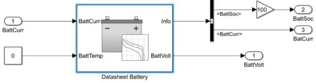
The battery pack is packed with 30 numbers of cells in series and 2 numbers of cells in parallel each.
Rated capacity of the battery (Ah) = 100
Output Voltage = 12V
The Battery rated capacity is 100 Ah and rateed voltage is 12 volt the battery provides 1200kwh considering its charging/ discharging.
Charging of battery: If the applied current is 10 amperes, then it would be 100Ah/10A=10 hrs. approximately.
Discharging: Battery Ah X Battery Volt/ Applied load say, 100Ah X 12V/100 watts = 12 hrs. (With 40% loss at the max =12 x 40/ 100 = 4.8 hrs). The Backup will last up to 4.8 hrs.
Formula to calculate SOC = SOC(t) = SOC(t-1)+`intI(/C_(Bat.dt)`
Where SOC(t) = State of charge at time t
SOC(t-1) = Initial state of charge
I = charge/discharge current(A)
T = time(H)
The BattCurr and the BattVolt are connected to the motor controller respectively, the batt SOC can be determined by the bus selector SOC is scaled to 100 by using a gain block.
Parameter for Battery-
1. Battery Type = Lithium-Ion Battery
2. BattchargeMax = 100Ah
3. No of Cells in Series = 30
4. No of Cells in Parallel = 2
5. Output Battery Voltage = 12V
Driver-
The Driver block is basically a controller for the vehicle, it controls the acceleration, and braking of the vehivle. The block is implemented with a PID controller which is basically the main controller in the whole drive cycle. The PID controller works as colsed loop speed control, it takes the input as a reference speed and correct the erroe genereted by the vehicle speeds. PID conroller is tuned for the adequate acceleration and deacceleration command itis done by limiting its output to upper and lower saturation. Separting the output of the PID to accelerate and deacceleration command we use a saturation block for each command, for acc command we use an upper saturation value and for the deaccelerate command, we use a lower saturation value.
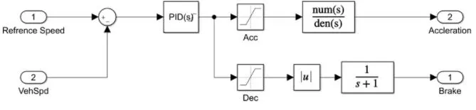
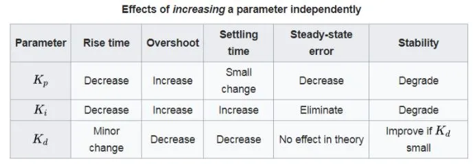
Tuning is Proportional, derivative and integral values we should be able to track the reference speed. The below table gives us an idea for the manual tuning of the controller.
Result-
Taking all the above factors into consideration we now run the simulation the reference speed here is Artemis Motorway (130Kmph).
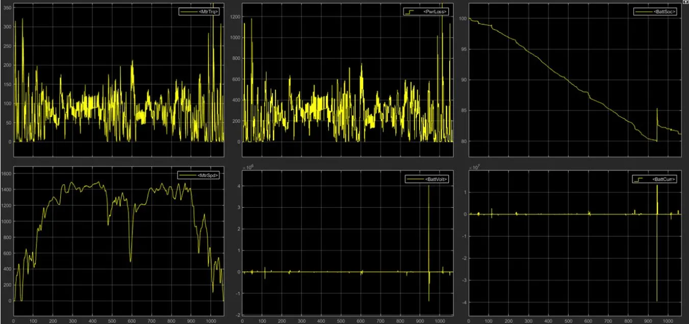
The simulation was run for about 1068 sec and we have obtaoned result shown above. There are 6 individual graphs showing the result for motor nd the bateery in this result, we see that a max torque of about 400Nm was obtained and a max speed of the motor was about 1500rpm at 130kmph. The graph of the battery SOC shows a linear and a slow discharge rate, we alwo observe a peak of charging spike at about 950 sec as a cause by the regeneretive braking of the vehicle. The Result for the Vehicle speed and reference speed is shown below-
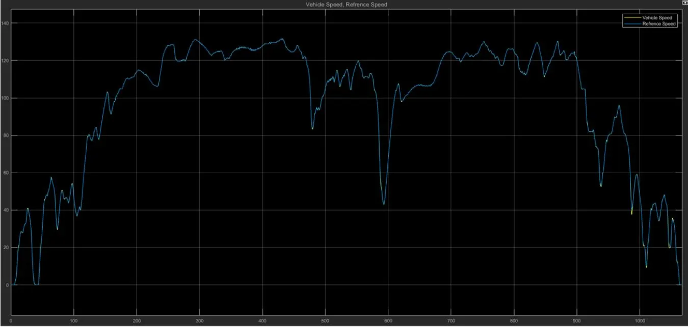
We can see that the vehicle speed tracks the reference speeds Artemis Motorway thanks to the PID controller, the manual tuning of the PID controller help to track the reference speeds.
Conclusion-
The Efficiency of the Electrical Vehicle is more compare to normal IC vehicle of HEV Vehicle, Also the run time cost of the vehicle is very low-e.g.-
Full Range =130km
Total consumption of electricity at full charge = 16.5 units
Electricity usage per km = 1+.5/130 = 0.12units
Cost of 1 unit electricity = 4.5Rs
Total cost of runing for 1 km = .12*4.5=0.54p
Total cost of runing for 130km 15.6Rs
The power losses are comaratively less than a conventional vehicle as they use a complex gear system but to use the EV at the full potential there is a need to increase a public charging station. The Manufacturing of Electric vehicles is domestic, for instance, come at a high cost, production of battery is largely expensive due to material like cobalt hence there is a need to find an alternate for such materials.
There is a need for adoption of thr electric vehicle especially for india as it could save up to $300bn in oi; imports and 1 gigaton of co2 emmision.