Project 1 (Mini Project on Vehicle Direction Detection
A. Objective:
- Development of MATLAB Simulink model as per requirement- Requirement 1 and 2.
- Tag the requirements to the Simulink model; tagging requirement 1 & requirement 2 to their corresponding subsystems is fine.
- MBD compliant changes, Data Dictionary creation & code generation is added advantage, and that is not scope of this project.
- If choosing code generation, Storage class for Input signals: ImportedExtern; Storage class for Output signal: Export to File; Storage class for local signals: localizable; Storage class for calibration signals: Const.
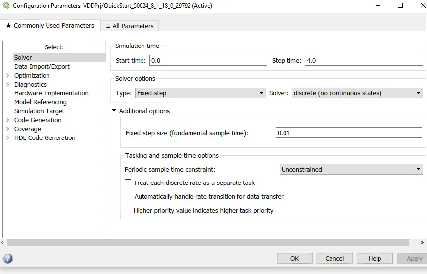
- Choose sample time for all signals as 0.01s
B. Simulink Model:
Steps:
1. Create Data dictionary
Create data dictionary of all signals as follows:
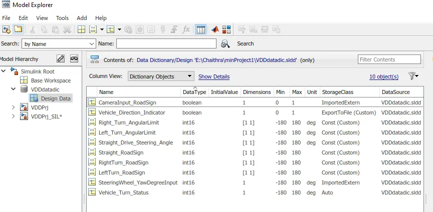
Created data dictionary which includes all input, output and local signals with file name VDDdatadic.sldd.
As I have used 2017a version of MATLAB, localize storage class is not available for local signal so assigned auto as storage class for local signal.
2. Link Data dictionary to the Model
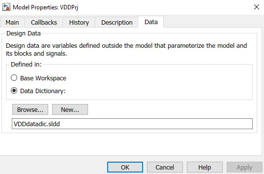
The data dictionary is linked using Model properties as shown in the above
3. Implement the requirement as per requirement document
Main Model:

The main model consists of 2 subsystems: Steering Wheel System and Camera input System.

I have set sampling time as 0.01 s as per the objective mentioned above.
Requirements modelled in 2 different subsystem as follows:
Blocks Used in model are:
1. Constant block
2. From & Go To tag
3. Logical block
4. Relational operator Block
5. Switch block
Requirement - 1:
- Steering wheel input as yaw rate (Signal name: SteeringWheel_YawDegreeInput) is the input for this system.
- This is compared against 3 angular values, one each for left turn, right turn & straight drive (Calibration Values: Right_Turn_AngularLimit, Left_Turn_AngularLimit, Straight_Drive_Steering_Angle) to say which specific direction the steering wheel is turning towards.
- Use switch blocks to compare & develop this requirement. Keep this requirement in a subsystem & output of this requirement is a local signal (Signal Name: Vehicle_Turn_Status).
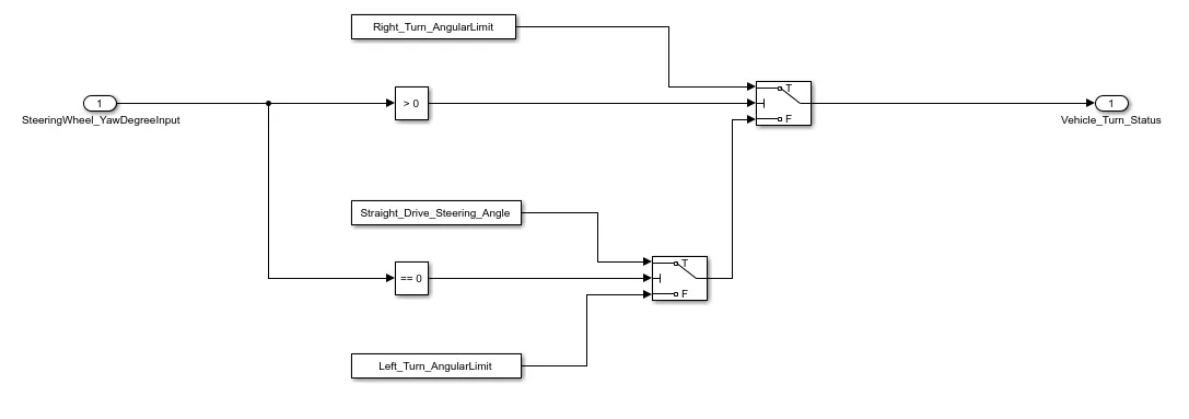
- Here i have used constant ,relational and switch block to create model for requirement1.
- Here iam comparing SteeringWheel_YawDegreeInput with Right_Turn_AngularLimit, Left_Turn_AngularLimit, and Straight_Drive_Steering_Angle as shown in the model.
- If SteeringWheel_YawDegreeInput is greater than 0 then vehicle_turn_Status will give Right_Turn_Angularlimit data as output. Simillarly, if SteeringWheel_YawDegreeInput is less than 0 then vehicle_turn_Status will give Left_Turn_Angularlimit data as output else it gives Straight_Drive_Steering_Angle data as output.
Requirement – 2:
- Keep this requirement as a separate subsystem. Inputs to this requirement are local signal from requirement 1 (Signal Name: Vehicle_Turn_Status) & an input signal from camera (Signal Name: CameraInput_RoadSign), which confirms the occurrence of a road sign.
- Signal Vehicle_Turn_Status is compared against calibration values (Calibration Values: RightTurn_RoadSign, LeftTurn_RoadSign, Straight_RoadSign), if each of them is found equal, then each of the three corresponding output is compared against the camera input signal,
- Using a logical operator block, only one among them is finally given as output signal (Signal Name: Vehicle_Direction_Indicator).
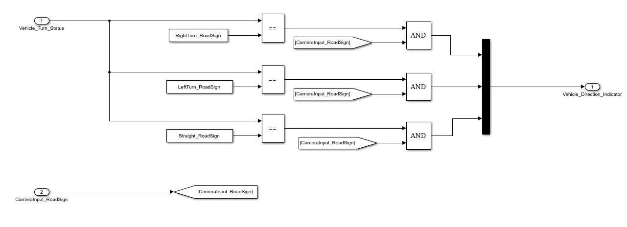
- Here i have used constant ,relational ,mux and logical block with from and Goto tags to create model for requirement2.
- Here iam comparing vehicle_turn_Status with RightTurn_Roadsign, LeftTurn_Roadsign, and Straight_Roadsig as shown in the model. And compared output is anded with CameraInput_Roadsign and the output is fed to mUX as shown in the model above.
- If vehicle_turn_Status is equal to RightTurn_Roadsign, then its output will be anded with CameraInput_Roadsign. If both of these are giving output as 1 then the Vehicle_Direction_Indicator shows driver to take right turn. Similar logic is followed for left and straight turn as well.
Requirement Tagging:
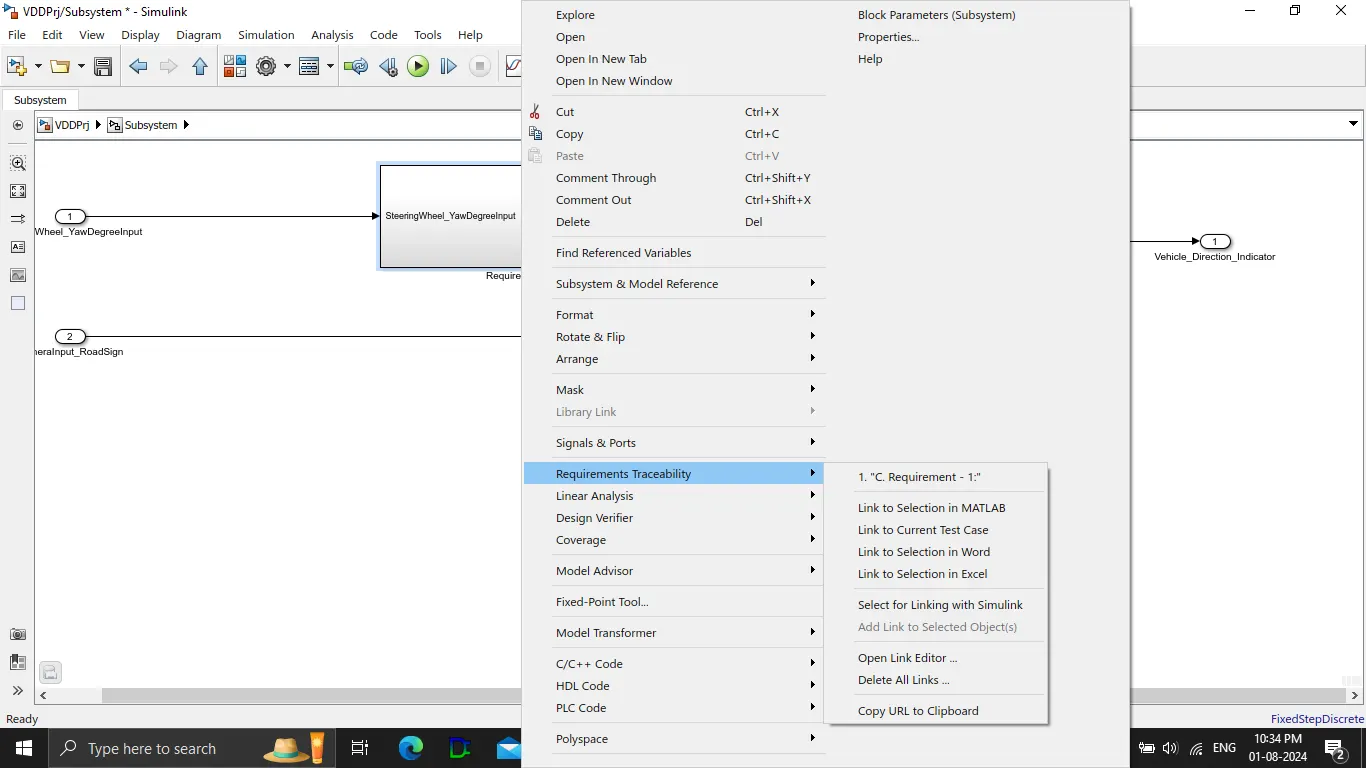
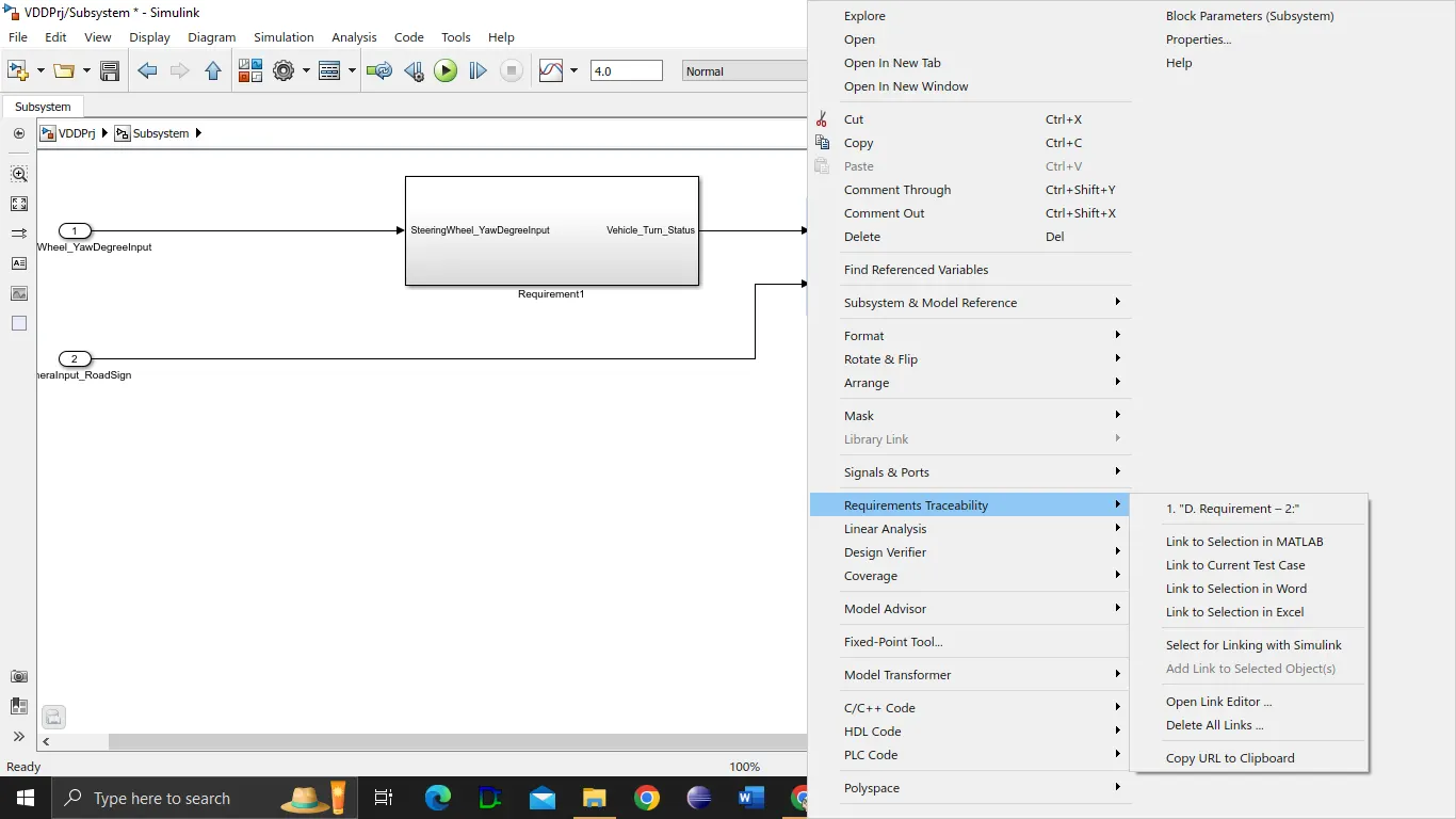
Created requirement document in word format and requirement is tagged to each subsystems as shown in the above figure.
Steps to follow to tag requirement is :
Go to 'requirements and traceability' menu by right clicking on the subsystem and select 'Link to selection in word' option.
Model advisor Check:
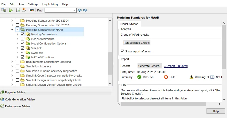
I have performed Model advisory check on my model.
Here I am checking only 'Modelling Standards for MAAB ' so done 'Run selected Checks' .
After check we found there is 0 fail as shown in the above.
Testing Model:
Testing of model is performed using MIL and SIL testing method.
Test Seq used in both MIL & SIL :
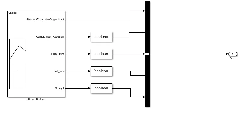
As Iam using 2017b version , there is no option available to generate Test Harness readily, so used the below Test sequence to perform both MIL and SIL testing.
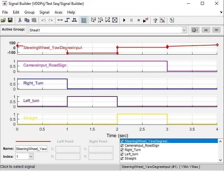
Here I have used Signal builder, data type conversion and bus selector blocks.
MIL Testing:
Creating MIL template:
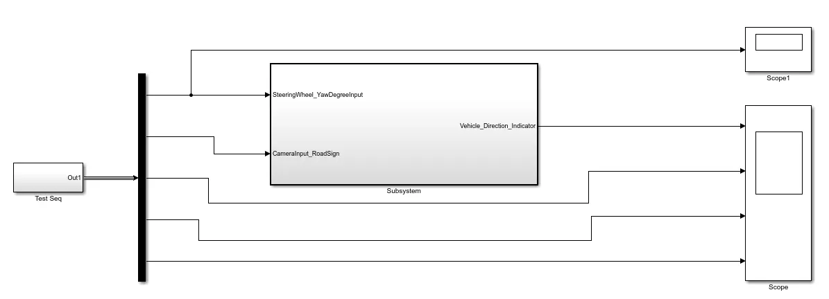
Here I have used test seq, demux and main model in subsystem and 2 scope as shown in the above figure.
Scope1 shows the input signal data and scope shows the output data.
SIL Testing:
Code Generation:
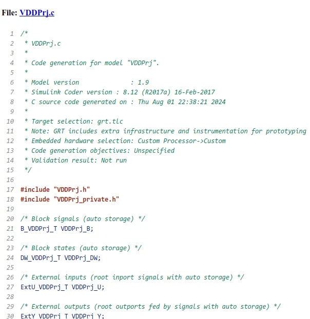
Before Performing SIL testing I have generated c code for the model and the sample code is shown in the blow figure.
Creating SIL template by using s function:
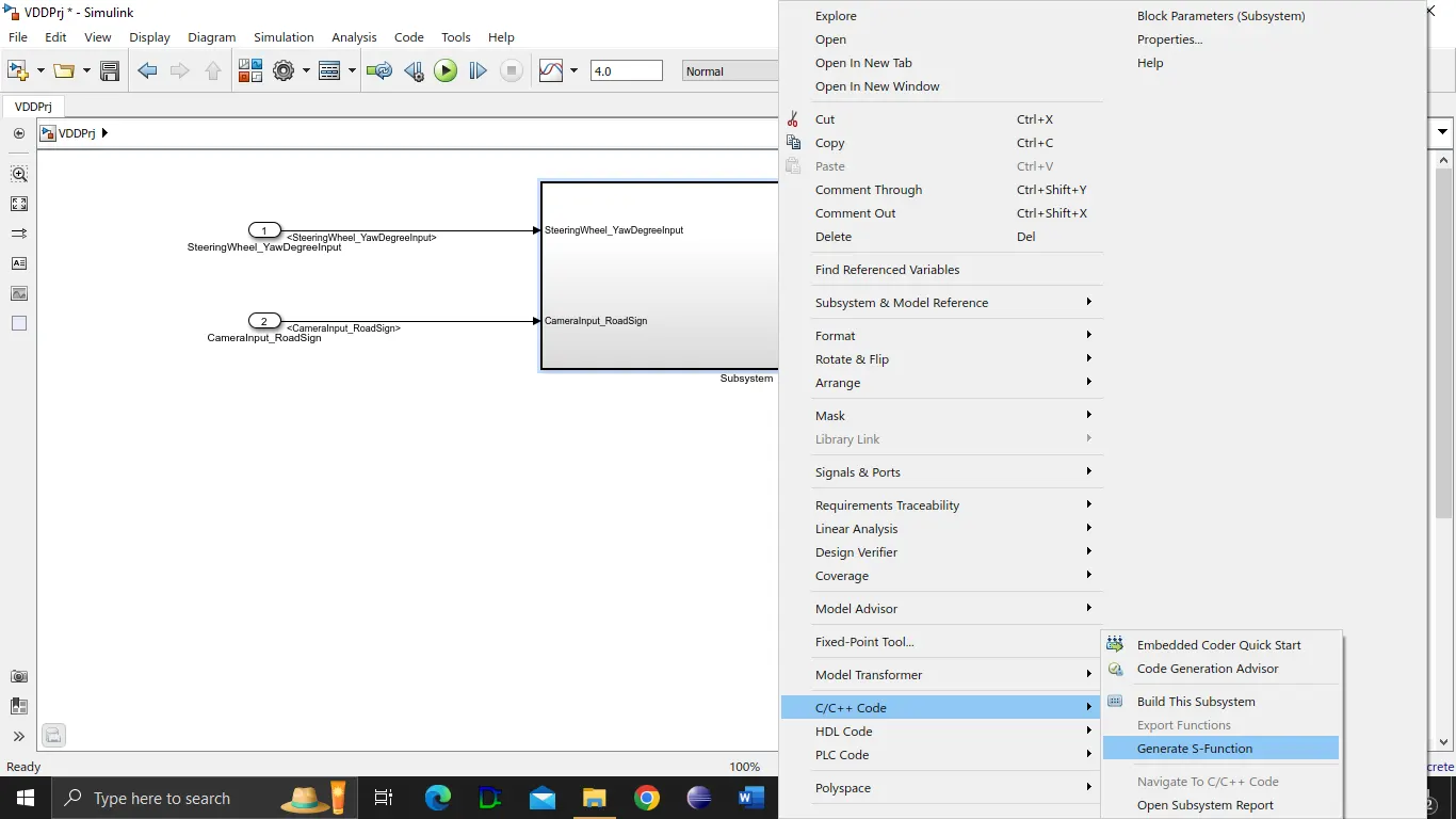
First I have created S-function of main model as shown in the figure below.
Right click on main subsystem select c/c++ code followed by select ''Generate S-function.
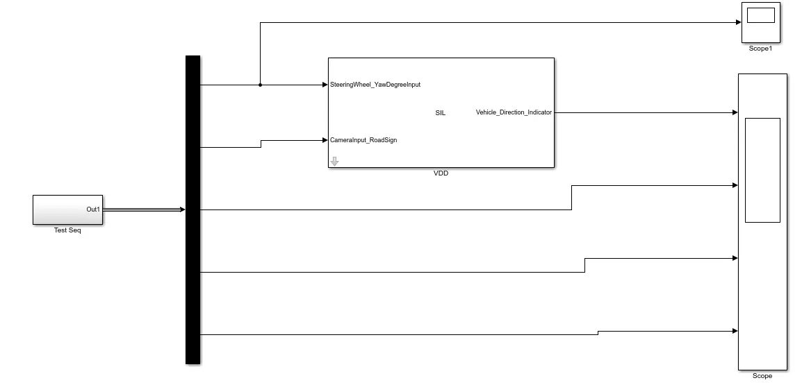
Here I have used test sequence ,demux, s function and scope blocks as shown in the above figure.
C. Results:
Testcase fed to Signal builder for both MIL and SIL testing:
The below test cases are used to test model using both MIL and SIL
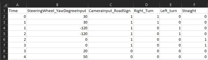
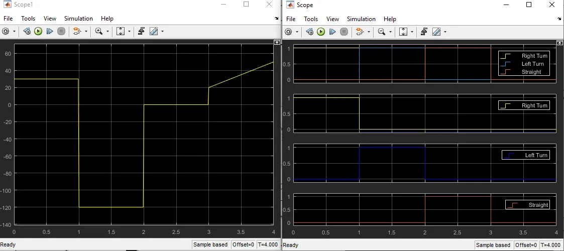
The right hand scope shows the input signal SteeringWheel_YawDegreeInput as per test cases in the excel sheet shown in the above figure.
The Left hand side scope has 4 rows shows in scope.
1st row has the output from main model. Yellow signal is for right turn, blue signal is for left turn and red signal is for straight signal.
Rest 3 rows are are the outs from test sequence. here both 1st row and rest 3 rows are matching each other as we can observe from the above graphs.
D. Conclusion:
1. Developed MATLAB Simulink model as per requirement- Requirement 1 and 2 with 0.01s sampling tme.
2. Requirement tagging is done separately for each subsystem.
3. Create Data dictionary and link it to the main model .
4. Performed Code generation using embedded coder.
5. Performed MBD compliant check.
6. Performed MIL and SIL testing.